


-
A fish-eye lens is a kind of bionic system that imitates the eyes of underwater fish looking up at the upper half of the world. By designing the function of a fish eye as an optical instrument, it becomes a fish-eye lens. The development history of fish-eye lenses can be found in Ref. [1]. Such a lens can satisfy people's purpose of obtaining information with as wide a field-of-view (FOV) as possible[1]. Usually, a lens with a FOV angle exceeding 140° is considered a fish-eye lens. Fish-eye lenses belong to the ultra-wide-angle lens family, which meets the needs of information acquisition in modern warfare, and it is an advanced technology developed by different countries. Therefore, fish-eye lenses have been widely used in national defense and military fields. Fish-eye lenses are also widely used in photography, spherical screen projection, meteorological monitoring, safety monitoring, engineering measurement, and micro-intelligent systems.
Fish-eye lens systems are usually optical systems consisting of a front group and a rear group. The front group of lenses are usually composed of negative meniscus lenses with greater absolute focal power. The first lens, in particular, has basic characteristics of much larger negative focal power and is a reflective telephoto objective lens. The rear group has the characteristics of positive focal power. The main function of the front group of a fish-eye lens is to compress the FOV angle obviously smaller after the incident light passes through the front group, which is beneficial to the design of the rear group and the aberration correction of the entire system.
To make an overview of the object being observed in a large area with small magnification and to make a careful observation of the object being observed in a small area with large magnification, the zoom optical system has emerged as demanded by modern observation requirements. There are two types of zoom optical systems in principle: optical compensation and mechanical compensation. The latter has become the basic type of a zoom optical system. In the zoom process of a zoom lens, by enlarging or reducing the focal length of the lens system, different parts of the object can be clearly observed. These functions are not available with a single fixed-focus lens. Therefore, in many cases, a zoom optical system can better meet the needs of various fields. Nowadays, zoom optical systems are being developing in the direction of much larger FOV angle, much larger relative aperture, higher magnification, smaller volume, and clearer imaging.
Facing the demand of the application and development of zoom lenses, how optical designers achieve the design goal is also a difficult point in the zoom optical system design process[2–4]. In this paper, a zoom fish-eye lens system with large FOV and large relative aperture is designed for photographic use.
In the next section, the details of the design of a fish-eye lens system in the visible light band with fixed focal length and a 180° FOV angle is presented[5]. The imaging quality of this zoom optical system is very good. In Section 1, we introduce zoom design principles and four rules of the zoom process in the zoom lens system. In Section 2, we detail the zoom fish-eye lens process, including design specifications for zoom fish-eye lenses and initial structural design for both fixed-focus and zoom fish-eye lenses. In Section 3, aberration analysis of the designed zoom fish-eye lens system is carried out.
Through the division of zoom components and further optimization of the fixed focal length fish-eye lens system, a zoom fish-eye lens system with large aperture, stable image surface, and clear image is finally obtained. Its focal length can be changed continuously from 8 mm to 16 mm.
-
There are four main rules in the zoom process for a zoom lens system[6]. In a zoom optical system, because the focal length of each component is fixed, the focal length of the entire system can only be changed by changing the distance between the components of the groups. These rules are the following.
(1) The stability of the image plane depends on the zero sum of the conjugate distance changes of each motion component, as shown in Fig.1. This system is composed of two components Φ1 and Φ2, A is the object point, A' is the image point, where q1 and q2 are the respective moving distances of zoom group Φ1 and compensation group Φ2 along the axis direction, and L1 and L2 are respectively the conjugate distances of zoom group Φ1 and Φ2 before the lens moves along the axis. L1' and L2' are the conjugate distances of zoom group Φ1 and Φ3 after the lens moves along the axis.
Figure 1. Conjugate distance graph of Φ1 and Φ2 groups
$$ \mathop \sum \limits_{i = 1}^{{2}}\Delta {L_{{i}}} = \left( {{{{L}}_1} - {{L}}_1^{{'}}} \right) + \left( {{{{L}}_2} - {{L}}_2^{{'}}} \right) = 0 $$ (1) That is to say, no matter how complex the zoom system is, to keep the image position still, the conjugate distance changes caused by each component should be completely offset from each other.
(2) When any component moves from one position to another, its conjugate distance remains unchanged; that is, the positions of the object surface and image surface remain unchanged, while the magnification of components is reciprocal at two positions.
(3) For any motion component the focal length of which is f', when its magnification m is −1, the conjugate distance of the component reaches the minimum value, which is
$$ {L_{{\rm{min}}}} = 4{{f}}' $$ (2) (4) The zoom equation of the zoom system is to explain the motion equation of the motion component under the condition that zoom and image displacement are compensated, and is expressed as
$$\mathop \sum \limits_{i = 1}^{{n}} \frac{{1 - m_i^2}}{{m_i^2}}f_i^{{'}}{\rm{d}}{m_i} = 0$$ (3) where m is the longitudinal magnification of each component, and f' the focal length of each component, n is the number of the motion components. The meaning of this formula is that, to keep the position of the image plane unchanged, the sum of the differential changes of the conjugate distances of all motion components at any instant is zero; that is to say, the differential changes of the conjugate distances caused by the movement of each motion component must offset each other.
The zoom equation of the zoom system explains the motion equation of motion components of the zoom system under the condition of zoom and image displacement compensation.
-
There are two main stages in the full design process of the zoom fish-eye lens system: one is the initial structural design stage and the other is the components planning and overall optimization design stage. The overall optimization design stage of the zoom fish-eye lens system is divided into the Gaussian solution stage and the aberration-reduction design stage.
-
The zoom fish-eye lens designed and reported on in this paper is a lens in the visible-light band with an F number of 3.5, with the focal length of the system able to change from 8 to 16 mm when the FOV angle of the system changes from 180° to 90°. The modulation-transfer-function (MTF) requirement is that, when the space frequency is 50 lp/mm, the modulus of the optical transfer function (OTF) is no less than 0.45. The size of the image plane is 0.671 7 in., and the aspect ratio of the image plane is 4∶3. The design specifications of the zoom fish-eye lens system are listed in Tab. 1.
Table 1. Design specifications
Focal length state Short Middle Long Focal length/mm 8 12 16 F number 3.5 3.5 3.5 FOV/(°) 180 120 90 BFD/mm 17 30 42 Design spectrum Visible light (F, D, C) Maximum lens clear aperture /mm 82 Object location At infinity When the space frequency of the MTF requirement is 50 lp/mm, the corresponding minimum pixel size is 1/(2×50)=0.01 mm; when the offset of 0.671 7 in. (approximately 17.061 2 mm) is 100%, the radius of the field of view at the image plane is 12.303 mm, as shown in Fig. 2. The total pixels value of the long edge in the image plane is 13.648 9/0.01=1 364.89, while that of the short edge in the image plane is 10.236 7/0.01=1 023.67; the minimum total number of image-plane pixels is 1 364.89×1 023.67 =2 278 475.745 4≈1.397 million, and a resolution of 1.397 million pixels is needed.
Figure 2. Circle radius diagram of field of view. Radius of the image plane is 12.303 mm, aspect ratio of the image plane is 4:3, length of the long side is 13.648 9 mm, and length of the wide side is 10.236 7 mm
-
In the work reported in this paper, Lu's initial structural design method was used to design the initial structure of the fish-eye lens[7]. A fish-eye lens system usually consists of the former group that is composed of negative meniscus lenses used to compress the FOV angle of incident light and the rear group objective lenses composed of conventional optical lenses. The general design idea is to determine the parameters of the former-group optical system according to the restriction conditions and then choose the structure and parameters of the rear-group objective lenses according to the FOV angle and aberration distribution of the former-group optical system in the image space. The former- and rear-group structural parameters restrict each other. For example, the small radius of each negative meniscus lens should satisfy the transverse and longitudinal size limitations of the fish-eye lens, and the ratio of small radius to large radius and the selection of refractive index n should satisfy the requirement of the FOV angle compression ratio. At the same time, some aberrations, such as field curvature, should be controlled reasonably, and the free parameters should also be controlled. The design restrictions include the lateral and vertical dimensions of the fish-eye lens, FOV angle requirements, image-plane parameters, rear-top focal length, imaging quality, and relative aperture requirements.
-
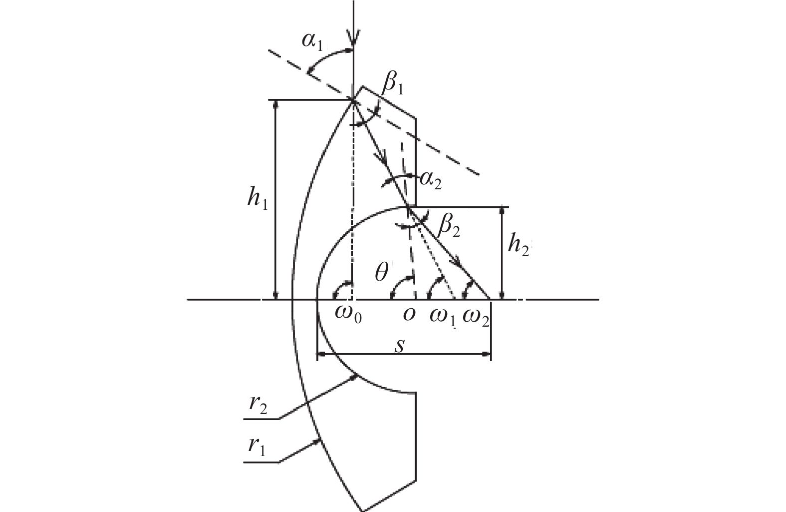
Figure 3 shows a negative meniscus lens for the former group of a fish-eye lenses system. Its respective curvature radii are r1 and r2. A beam of chief rays impinges the first surface at an angle of ω0 with the axis. The vertical distance from the intersection point of the chief rays and the first surface to the optical axis is h1. After passing through the first surface, the chief rays enter the first lens at an angle of ω1 with the axis, and the chief rays at an angle of ω2 with the axis pass through the second surface. The vertical distance from the intersection point of the chief rays and the second surface to the optical axis is h2, the angle of incidence angle on both surfaces is α1 and α2, respectively, the angle of refraction angle on both surfaces is β1 and β2, respectively, and the angle between the optical axis and the normal line of the chief rays at the intersection of the second surface is θ. The distance between the intersection point of the chief rays passing through the second surface and the optical axis to the vertex of the second surface is expressed as follows[7]:
Figure 3. Optical scheme of a principle ray passing the negative meniscus lens
$$s = {r_2}\left( {1 + \frac{{\sin \left( {{\theta _2} - {\omega _2}} \right)}}{{\sin {\omega _2}}}} \right)$$ (4) $$ \sin \theta = \frac{{{h_2}}}{{{r_2}}} \equiv k $$ (5) The FOV angle of the image space can be obtained by tracing the chief rays. The chief-ray transmission equation is
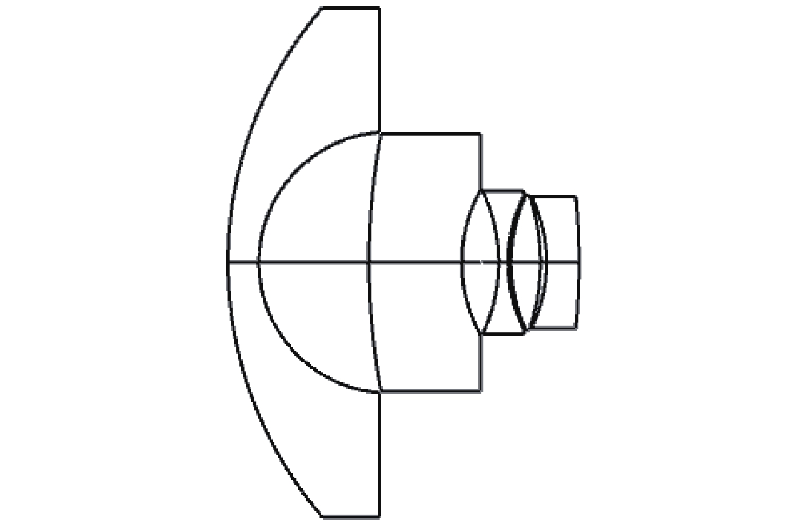
$$ \sin {\alpha _{{\rm{i}} + 1}} = \frac{{{r_{i + 1}} + {d_i} - {r_i}}}{{{\rho _{i + 1}}}}\sin {\omega _i} + \frac{{{\rho _i}}}{{{\rho _{i + 1}}}}\sin {\beta _i} $$ (6) $$ {\omega _{\rm{i}}} = {\omega _{i - 1}} + {\beta _i} - {\alpha _i} = {\omega _0} + \sum\limits_{i = 1}^i {\left( {{\beta _i} - {\alpha _i}} \right)} $$ (7) $$ {\beta _j} = \arcsin \left( {\frac{{{n_{i - 1}}}}{{{n_i}}}\sin {\alpha _i}} \right) $$ (8) where i is the ordinal number of the optical surface, ni and ni+1 are the refractive indexes on both sides of optical surface i, and ρi is the curvature radius of the sagittal direction of the optical surface i. ri is the curvature radius of the meridional direction of the optical surface i, and di the distance between optical surfaces i and i+1. The lenses before the stop form the former group, and the lenses behind the stop form the rear group. The design results of the former-group lenses are shown in Fig. 4. The former group consists of five independent spherical lenses. The first three lenses and the fifth lenses are spherical lenses with negative focal power. The fourth lens is spherical lens with positive focal power. The first lens plays a key role in compressing the FOV angle, and its vertical dimension is also the largest. The lens data of the former group are provided in Tab. 2.

Figure 4. Structural schematic of former-group lenses
Table 2. Zoom fish-eye system lens data
Surface
No.Radius of
curvature/mmThickness
/mmClear semi-
diameter/mmMaterial Object Infinity Infinity Infinity − 1 63.780 5.000 41.339 N-LASF44 2 21.275 17.743 21.196 − 3 111.335 15.000 20.895 N-LASF31A 4 24.477 5.935 11.815 − 5 −27.455 1.500 11.638 N-PSK57 6 24.085 0.501 10.935 − 7 26.056 4.740 10.976 SF6 8 −34.085 0.999 10.908 − 9 −24.292 5.208 10.706 N-LASF31 10 −114.211 T10 (variable) 10.548 − 11 42.004 13.883 8.609 N-LASF31A 12 2919.058 0.310 7.609 − 13(stop) Infinity 0.100 7.565 − 14 166.120 1.500 7.652 N-LASF31A 15 18.654 3.388 8.087 K3 16 −37.711 0.100 8.283 − 17 29.232 4.366 9.190 N-FK5 18 −21.084 1.500 9.271 N-LASF31A 19 147.645 0.100 10.014 − 20 45.442 11.616 10.449 TIFN5 21 −28.907 0.100 11.721 − 22 −332.106 1.500 11.721 N-LASF40 23 22.817 5.807 11.800 N-PK52A 24 −46.204 9.140 11.955 − 25 39.680 15.000 13.434 N-FK5 26 124.266 T26 (variable) 12.861 − Image Infinity − 12.303 − -
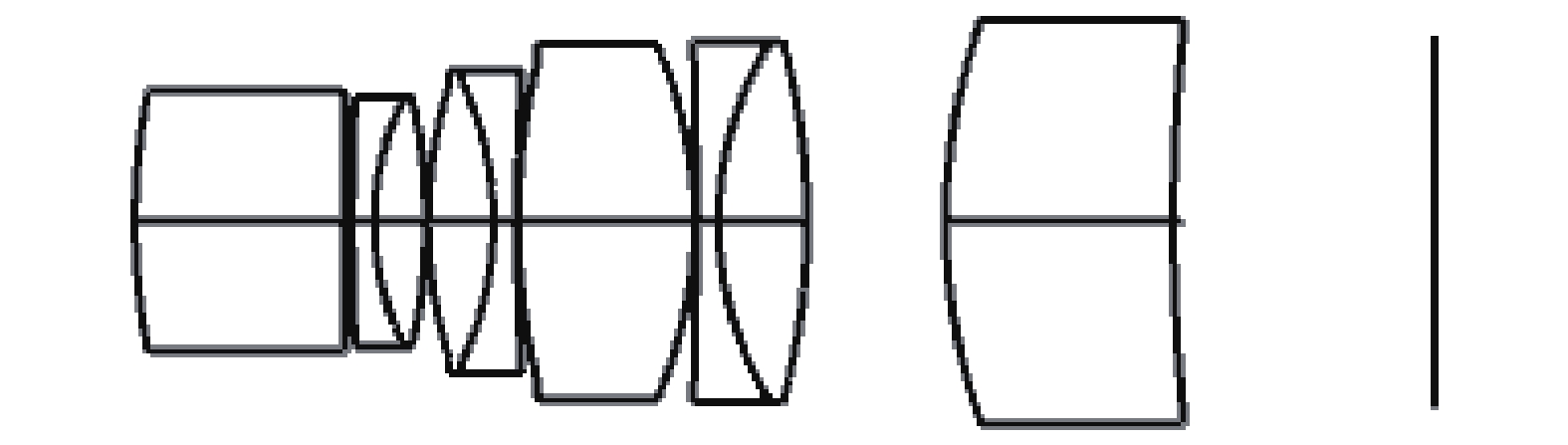
For the rear-group lenses design, the design boundary conditions are basically determined, such as FOV angle, relative aperture, rear top focal length, and size of the image plane. Of course, the imaging-quality requirements are the most important. The main aberration distributions produced by the former group of optical systems, such as field curvature, axial chromatic aberration, and vertical chromatic aberration, should be taken as the boundary conditions for the design of the rear-group lenses. The coma and spherical aberration can be further optimized by the shape parameters of the lens, and then the optical focal distribution and axial size of the rear-group lenses can be determined[8–10]. Nine spherical lenses are selected as the initial structure of the rear group after coordination and combination of the former and rear groups. The design results of the rear-group lenses are shown in Fig. 5. The seventh and eighth lenses, ninth and tenth lenses, and twelfth and thirteenth lenses comprise three groups of doublet lenses. The lens data of the rear group are given in Tab. 2.

Figure 5. Structural schematic of rear-group lenses. the eleventh and thirteenth lenses are independent spherical lenses. The last plane is the image plane
Glass materials were chosen from the Schott glass catalogue. The surface of each lens in this fish-eye lens is spherical. The modulus of the OTF is no less than 0.45 in full FOV when the space frequency is 50 lp/mm.
-
To improve the zoom performance of the system, two zoom groups were planned[6], as shown in Fig. 6. The first five lenses form the front zoom group of the fish-eye lens system. The second zoom group is the rear zoom group, which is beneficial to the reasonable correction of aberrations of the entire system[11]. The rear zoom group includes the aperture stop, acts as the zoom group, and produces the majority of the lens movement to change the focal length of the system. The image plane positions remain unchanged.
Figure 6. Zoom-group planning. The first group is the front zoom group, the second group is the rear zoom group, and the last plane is the image plane
-
The aberration-reduction design phase consists of the following steps
(1) Calculate for the zoom optical system consisting of two groups of optical lenses with focal lengths f'1, f'2, and the distance between the groups being d12, d23 as determined by the movement q1 of the front zoom group and the movement q2 of the rear group the first auxiliary light height h and the second auxiliary light height hp for each component at three or more zoom positions, i.e., long, medium, and short focus.
(2) Determine a suitable set of values for m1l and f'2.
(3) Use the damped least-squares method to solve P∞ and W∞ for each component. The relationship between the primary aberration coefficients SI, SII, SIII, and SV and hi, hpi, φi, Pi, and Wi, when objects are at a finite distance, is expressed as follows:
$$ {{{S}}_{\rm{I}}} = \sum\limits_{i = 1}^k {h_i^4} \varphi _i^3{P_i} $$ (9) $$ {{{S}}_{{\rm{II}}}} = \sum\limits_{i = 1}^k {h_i^3} {h_{pi}}\varphi _i^3{P_i} - J\sum\limits_{i = 1}^k {h_i^3} \varphi _i^2{W_i} $$ (10) $$ {{{S}}_{{\rm{III}}}} = \sum\limits_{i = 1}^k {h_i^2} h_{{{pi}}}^2\varphi _i^3{P_i} - 2J\sum\limits_{i = 1}^k {{h_i}} {h_{pi}}\varphi _i^2{W_i} + {J^2}\sum\limits_{i = 1}^k {{\varphi _i}} $$ (11) $$ {{{S}}_{{V}}} = \sum\limits_{i = 1}^k {{h_i}} h_{{{pi}}}^3\varphi _i^3{P_i} - 3J\sum\limits_{i = 1}^k {h_{pi}^2} \varphi _i^2{W_i} + {J^2}\sum\limits_{i = 1}^k {\frac{{{h_{pi}}}}{{{h_i}}}} (3 + \mu ){\varphi _i} $$ (12) where J is Rach invariant, μ is the normalized field curvature coefficient, φi is the focal power of each component, h is the first auxiliary light height, and hp is the second auxiliary light height. In addition,
$$ \mu = \dfrac{{\displaystyle \sum\limits_{i = 1}^k {\dfrac{{{\phi _i}}}{{{n_i}}}} }}{{\displaystyle \sum\limits_{i = 1}^k {{\phi _i}} }} \approx 0.6 - 0.65 $$ (13) The relations between Pi,Wi and P∞, W∞ when objects are at infinite distances are expressed as follows:
$$ {P_i} = P_i^\infty + {u_i}\left( {4{W}_i^\infty - 1} \right) + u_i^2(3 + 2\mu ) $$ (14) $$ {W_i} = W_i^\infty + (2 + \mu ){u_i} $$ (15) $$ {u_i} = {u_i}/{h_i}{\varphi _i} = f_i^\prime /{l_i} $$ (16) Here, u is the planning angle.
(4) Decompose P∞ and W∞ to obtain the structural parameters of each component.
In the process of determining one group consisting of several lenses, the maximum light height and maximum relative aperture of the group should be combined to make a judgment separately. Then, the bending form of each component and the focal power distribution ratio of each lens must be determined. There is at least one set of doublet lenses in this part of the system.
(5) Modifying the aberration of the entire system will further optimize the entire system until it meets the requirements. Finally, the focal length of each component is accurately traced, and the precise displacement compensation curve of the motion component is calculated. The design of cam curve is a follow-up work.
The entire optical optimization design process is carried out using ZEMAX optical design software. The maximum FOV angle of the zoom fish-eye lens reaches 180°. We adopt the method of “equidistant projection” in the design process. Compared with a wide-angle zoom system, the zoom fish-eye system has a larger FOV angle, which makes the correction of coma, field curvature, magnification chromatic aberration, and distortion of the system particularly difficult. The balance of various aberrations is emphasized in the design[12-13]. The process of improving and optimizing the multiple structures design can be referred to Ref. [14].
In the Merit Function Editor of the ZEMAX software, different operands can be used to restrict the basic parameters and shape size of the lens, such as EFFL to control the effective focal length of the lens, DMLT to control the maximum aperture of the lens, TOTR to control the total optical length of the lens, and DIMX to control the maximum distortion of the lens field of view. MNCG, MXCG, and MNEG control the center of each lens, the center thickness, and the edge thickness, respectively, and FCGT and FCGS control the field curvature in the meridian and sagittal directions, respectively. SPHA, COMA, ASTI, AXCL, and LACL control the primary spherical aberration, primary coma, primary astigmatism, primary axial chromatic aberration, and primary vertical chromatic aberration, respectively.
-
The initial structure was optimized in ZEMAX software to obtain the zoom optimization structure[14-15], as shown in Fig.7, namely the states of three zoom positions: short, medium, and long focus. The effective focal length at short focal length is 8 mm, at medium focal length 12 mm, and at long focal length 16 mm. The total length this zoom fish-eye lens system is 163.963 mm in short and middle focus and 170.153 mm in long focus, which is the distance from the vertex of the first surface to the image plane. The total length of The relative aperture of the image space is 1/3.5 in all zoom positions, and the FOV angles are 90° for long focal length, 120° for medium focal length, and 180° for short focal length.
In the zoom process, the front and rear zoom groups move along the axis to achieve the zoom effect. The data of the zoom fish-eye lens system are presented in Tab.2 and multi-configuration parameters in Tab. 3.
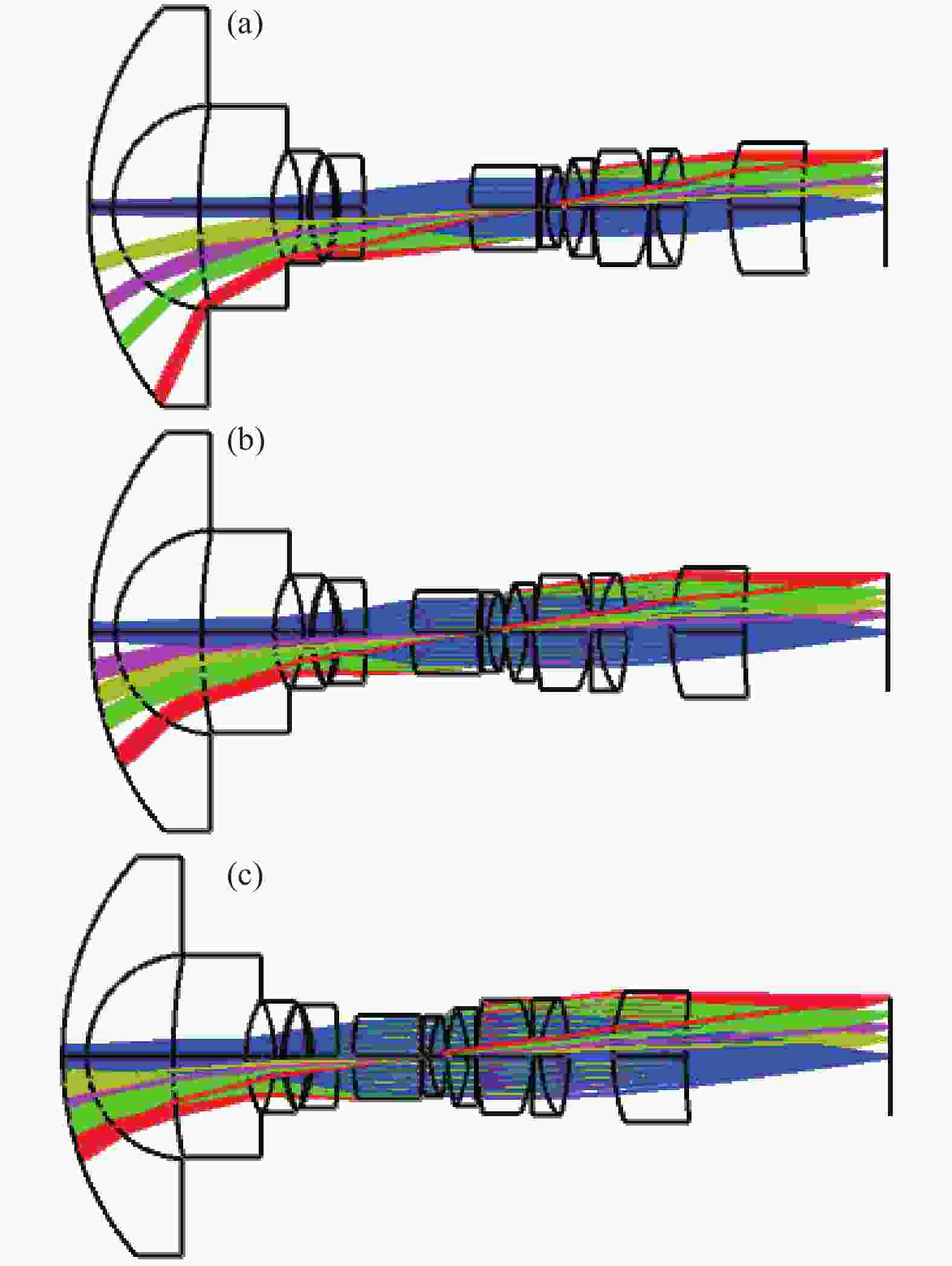
Figure 7. Optical path layout of three zoom states of the system. The first is the short-focal-length position with 8 mm system focal length, the second the medium-focal-length position with 12 mm system focal length, and the third the long-focal-length position with 16 mm system focal length
Table 3. Multi-configuration data
Focal-length state Short Middle Long Focal-length /mm 8 12 16 T10 /mm 21.761 9.350 3.167 T26 /mm 17.167 29.578 41.952 -
In the process of optimization design, system aberrations are effectively controlled by using effective optimization operands. At the same time, an appropriate vignetting coefficient is introduced to improve the imaging quality of the system at the expense of the edge illumination. To correct the aberrations produced by the zoom fish-eye lens system, the aberration of the system is briefly described by MTF curves, field curvature, distortion curves, and relative illumination curves.
MTF curves can objectively and reliably reflect the image quality of the system. In all kinds of optical systems, MTF curves are regarded as the most critical image-quality evaluation criteria. Here, the MTF curve is briefly analyzed and explained with the curves of different focal lengths. The MTF curve is smooth, which shows that the effect of image-quality level is obvious and close to the diffraction limit.
Figure 8(a) shows a zoom fish-eye system with a focal length of 8 mm and FOV angle of 180°. The modulus of the OTF is no less than 0.45 in full FOV when the spatial frequency is 50 lp/mm. Figure 8(b) shows a zoom fish-eye system with a focal length of 12 mm and FOV angle of 120°. The modulus of the OTF is no less than 0.51 in full FOV when the spatial frequency is 50 lp/mm. Figure 8(c) shows a zoom fish-eye system with a focal length of 16 mm and FOV angle of 90°. The modulus of the OTF is no less than 0.48 in full FOV when the spatial frequency is 50 lp/mm.
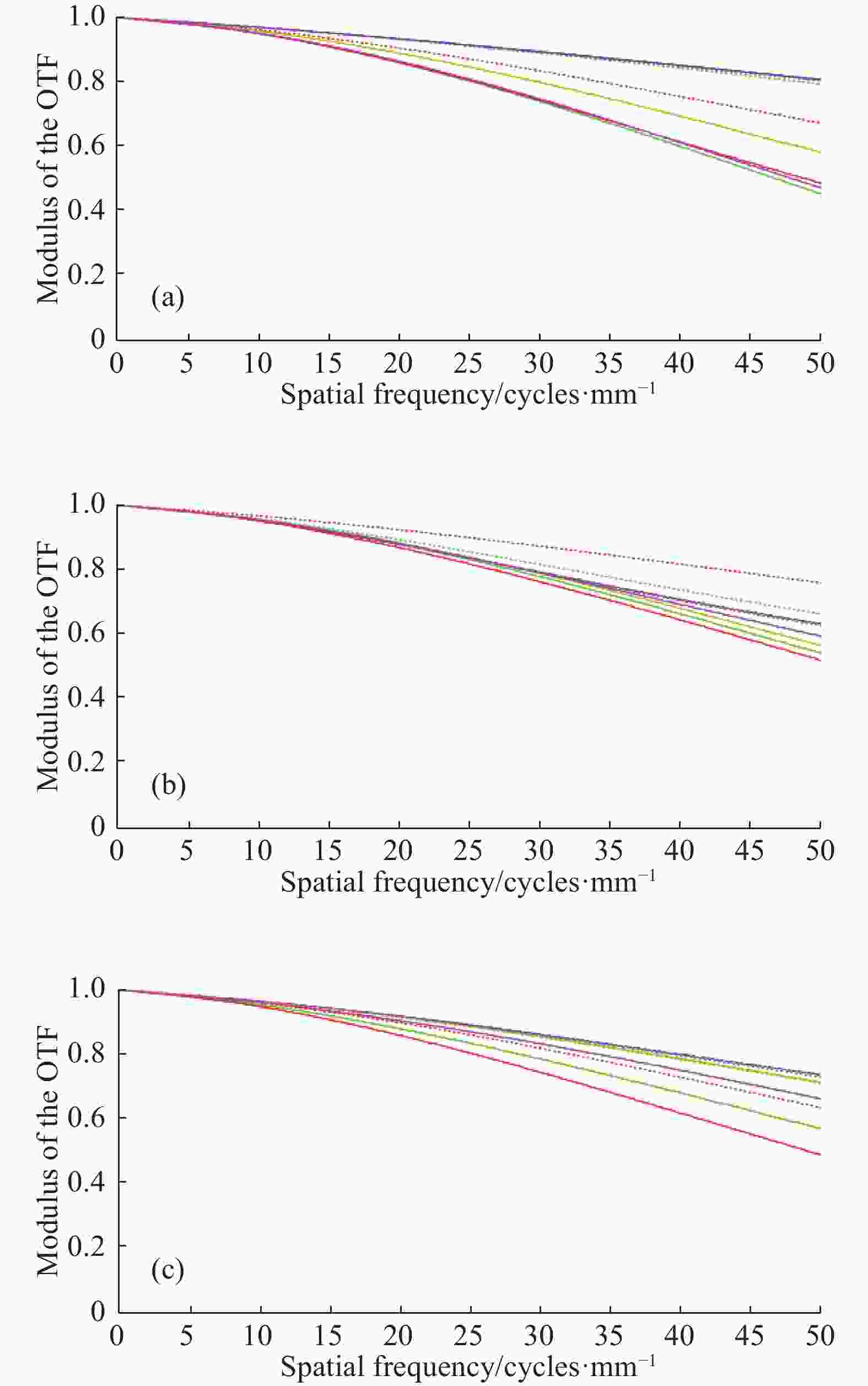
Figure 8. MTF curves of zoom fish-eye lens system with (a) 8 mm focal length and 180° FOV angle, (b) 12 mm focal length and 120° FOV angle, and (c) 16 mm focal length and 90° FOV angle
This zoom fish-eye lens system can satisfy the requirement of minimum the modulus of the OTF 0.45 when the spatial frequency is 50 lp/mm in three zoom positions, and the MTF curve is smooth, and the imaging quality of the edge and central FOV is better guaranteed. During the entire zoom process, the imaging quality can be maintained stably, and the imaging effect of millions of pixels of resolution can be achieved.
Figures 9(a) and (b) show the field curvature and distortion curves of the zoom fish-eye system at focal lengths of 8, and 16 mm, respectively. It can be seen that the absolute field curvature of all FOVs in the short-focal-length state does not exceed 0.082 mm, and the maximum distortion of the edge field of view is 87%. The absolute field curvature of all FOVs in the long-focal-length state does not exceed 0.13 mm, and the maximum distortion of the edge FOV is 21%.
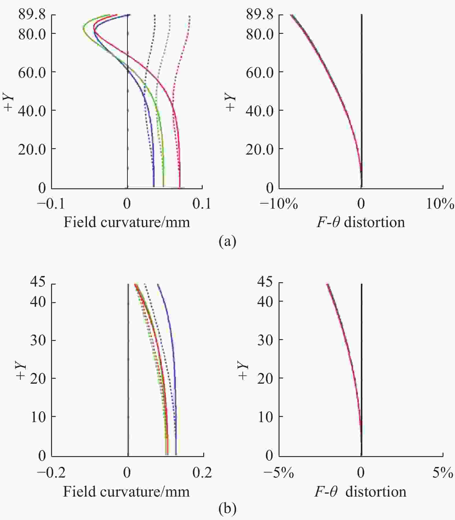
Figure 9. Field curvature and distortion curves for (a) short-focal-length (f=8 mm), and (b) long-focal-length (f=16 mm) positions
The field curvature of the zoom fish-eye lens system is controlled within 0.13 mm in the full FOV, and the aberration is small, except for distortion, especially in the short-focal-length state. For a panoramic lens, the distortion itself is very large. Such a large distortion can produce special imaging effects in practical application and is in high demand in some specialized fields. Such a large distortion can be further corrected[13].
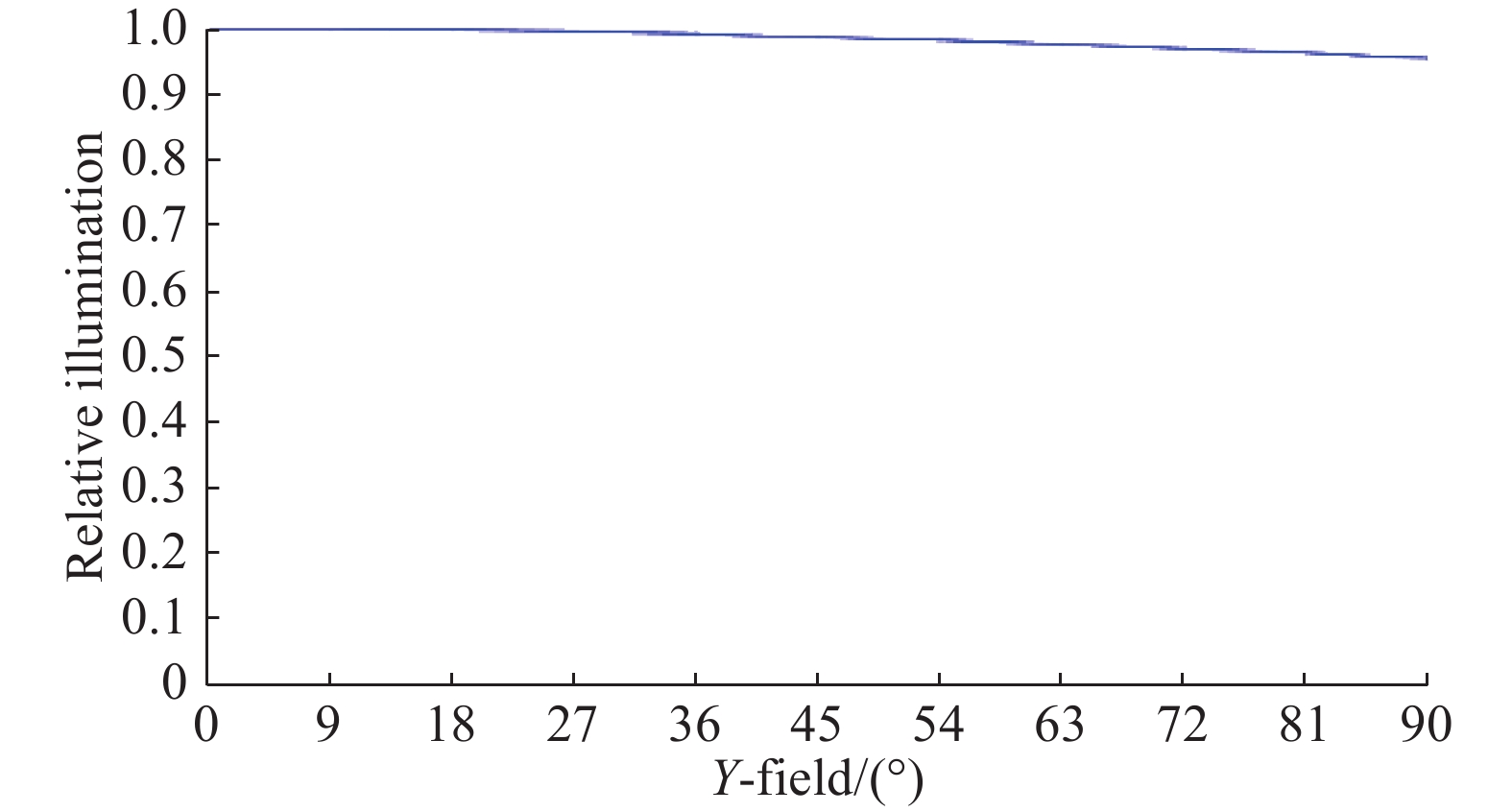
Figure 10 shows the relative illumination curve of the zoom fish-eye lens system at focal lengths of 8 mm. Comprehensive analysis shows that the relative illumination of the edge is no less than 0.96 when the focal length is 8 mm, which is mainly due to the decrease of the edge illumination due to the setting of the vignetting coefficient. When the focal lengths are 12 and 16 mm, the edge illumination is much higher than that of short focus state, and the uniformity of the image surface illumination is very good. The system guarantees the uniformity of illumination of the image plane in the process of continuous change of focal length and solves the problem of illumination attenuation caused by a large FOV.

Figure 10. Relative illumination curves at short-focal-length (f=8 mm) position
-
In this paper, the development trend of fish-eye and zoom lenses are briefly introduced, followed by a discussion of the motion equation of zoom systems. By combining the theory of a plane symmetric optical system and the Gaussian theory of zoom systems and fish-eye optical design theory, the initial structure of a fish-eye lens was designed. The lens features a large aperture compared to current designs on the market while maintaining constructional simplicity as it uses 14 spherical lens elements in two groups. Based on actual needs, the corresponding design indexes are formulated, the initial structure of the fish-eye lens further divided into two groups, and the aberration of the fish-eye lens system further optimized. All the components of this zoom fish-eye lens system adopt spherical surfaces, which are conducive to ease of manufacturing. As the second surface of the first negative meniscus lens of the zoom fish-eye lens system is almost the hemispherical shape, the problem that may be encountered in engineering application is that it is difficult to guarantee the eccentricity when processing this surface. Its F number is 3.5, and its focal length varies from 8 to 16 mm. Finally, aberration analysis, including MTF curves, field curvature, distortion curves, and relative illumination curves, is provided and explained in detail.
-
摘要: 变焦鱼眼镜头系统具有更大的视场角、更大的相对孔径、更大的反远比的特点。文中的设计过程中,首先,利用平面对称光学系统理论设计了固定焦距的鱼眼镜头初始结构;然后,把此鱼眼镜头的组元划分为前变焦组和后变焦组两个变焦组,并利用了高斯光学理论对整个变焦镜头进行了变焦优化;最后,得到一成像质量良好的变焦鱼眼镜头。该镜头最短焦距8 mm时的视场角为180°,最长焦距16 mm时的视场角为90°,其相对孔径为1/3.5。设计结果表明:该变焦鱼眼镜头系统的调制传递函数(MTF)数值在不同的焦距长度、空间频率为50 lp/mm时均不低于0.45,该变焦鱼眼镜头物镜比其他变焦鱼眼镜头具有更好的成像质量。Abstract: The zoom fish-eye lens had the characteristics of much larger field-of-view angle, much larger relative aperture, and much larger anti-far ratio. In the work described in this paper, the initial structure of a fish-eye lens with fixed focal length was firstly designed using the theory of a plane symmetric optical system. And then the initial structure components of the fish-eye lens were divided into two groups, the former-group and the rear-group, and then the entire zoom fish-eye lens system was optimized using Gaussian optical theory. Finally, a zoom fish-eye lens system with good imaging quality was obtained. This fish-eye lens system had a field-of-view angle of 180° with an 8 mm short focal length and a field-of-view angle of 90° with a 16 mm long focal length. Its relative aperture was 1/3.5. The design results show that the modulation transfer function of this zoom lens system at different focal lengths is no less than 0.45 when the spatial frequency is 50 lp/mm. This zoom fish-eye photographic objective lens had higher imaging quality than other zoom fish-eye lenses.
-
Key words:
- zoom lens /
- fish-eye lens /
- former group lenses /
- rear group lenses /
- aberration correction
-
Figure 2. Circle radius diagram of field of view. Radius of the image plane is 12.303 mm, aspect ratio of the image plane is 4:3, length of the long side is 13.648 9 mm, and length of the wide side is 10.236 7 mm
Figure 5. Structural schematic of rear-group lenses. the eleventh and thirteenth lenses are independent spherical lenses. The last plane is the image plane
Figure 6. Zoom-group planning. The first group is the front zoom group, the second group is the rear zoom group, and the last plane is the image plane
Figure 7. Optical path layout of three zoom states of the system. The first is the short-focal-length position with 8 mm system focal length, the second the medium-focal-length position with 12 mm system focal length, and the third the long-focal-length position with 16 mm system focal length
Figure 8. MTF curves of zoom fish-eye lens system with (a) 8 mm focal length and 180° FOV angle, (b) 12 mm focal length and 120° FOV angle, and (c) 16 mm focal length and 90° FOV angle
Figure 9. Field curvature and distortion curves for (a) short-focal-length (f=8 mm), and (b) long-focal-length (f=16 mm) positions
Table 1. Design specifications
Focal length state Short Middle Long Focal length/mm 8 12 16 F number 3.5 3.5 3.5 FOV/(°) 180 120 90 BFD/mm 17 30 42 Design spectrum Visible light (F, D, C) Maximum lens clear aperture /mm 82 Object location At infinity  下载: 导出CSV
Table 2. Zoom fish-eye system lens data
Surface
No.Radius of
curvature/mmThickness
/mmClear semi-
diameter/mmMaterial Object Infinity Infinity Infinity − 1 63.780 5.000 41.339 N-LASF44 2 21.275 17.743 21.196 − 3 111.335 15.000 20.895 N-LASF31A 4 24.477 5.935 11.815 − 5 −27.455 1.500 11.638 N-PSK57 6 24.085 0.501 10.935 − 7 26.056 4.740 10.976 SF6 8 −34.085 0.999 10.908 − 9 −24.292 5.208 10.706 N-LASF31 10 −114.211 T10 (variable) 10.548 − 11 42.004 13.883 8.609 N-LASF31A 12 2919.058 0.310 7.609 − 13(stop) Infinity 0.100 7.565 − 14 166.120 1.500 7.652 N-LASF31A 15 18.654 3.388 8.087 K3 16 −37.711 0.100 8.283 − 17 29.232 4.366 9.190 N-FK5 18 −21.084 1.500 9.271 N-LASF31A 19 147.645 0.100 10.014 − 20 45.442 11.616 10.449 TIFN5 21 −28.907 0.100 11.721 − 22 −332.106 1.500 11.721 N-LASF40 23 22.817 5.807 11.800 N-PK52A 24 −46.204 9.140 11.955 − 25 39.680 15.000 13.434 N-FK5 26 124.266 T26 (variable) 12.861 − Image Infinity − 12.303 −
下载: 导出CSV
Table 3. Multi-configuration data
Focal-length state Short Middle Long Focal-length /mm 8 12 16 T10 /mm 21.761 9.350 3.167 T26 /mm 17.167 29.578 41.952
下载: 导出CSV
-
[1] Yan Yufeng, Sasian Jose. Photographic zoom fisheye lens design for DSLR cameras [J]. Opt Eng, 2017, 56(9): 095103. [2] Michael P C. Aberrations of holographic toroidal grating systems [J]. Appl Opt, 1983, 22: 1508−1518. doi: 10.1364/AO.22.001508 [3] Lu Lijun. Aberration theory of plane-symmetric grating systems [J]. Synchrotron Radiat., 2008, 15: 399−410. doi: 10.1107/S0909049508003658 [4] José Sasián. Theory of sixth-order wave aberrations [J]. Appl Opt, 2010, 49: D69−D95. doi: 10.1364/AO.49.000D69 [5] Hou Guozhu, Lu Lijun. Design of fisheye lens system in visible light range [J]. Optics & Optoelectronic Technology, 2018, 16(3): 90−95. [6] Tao Chunkan. Zoom Lens Design[M]. Beijing: National Defense Industry Press,1988.(in Chinese) [7] Lu Lijun, Wu Xuewei. Design of initial structure of fisheye lens [J]. Acta Optica Sinica, 2017, 37(2): 0208001. doi: 10.3788/AOS201737.0208001 [8] Kumler James J, Bauer Martin L.Fish-eye lens designs and their relative performance[C]//Proc SPIE, 2000,4093: 360-369. [9] Lu Lijun, Deng Zhiyong. Geometric characteristics of aberrations of plane-symmetric optical systems [J]. Appl Opt, 2009, 48: 6946−6960. doi: 10.1364/AO.48.006946 [10] Wang Yongzhong. Fisheye Lens Optics[M]. Beijing: China Science Publishing and Media, 2006.(in Chinese) [11] Thompson Kevin P. Multinodal fifth-order optical aberrations of optical systems without rotational symmetry: spherical aberration [J]. Opt Soc Am A, 2011, 28: 821−836. doi: 10.1364/JOSAA.28.000821 [12] Lu Lijun , Cao Yiqing. Sixth-order wave aberration theory of ultra-wide-angle optical systems [J]. Appl Opt, 2017, 56: 8570−8583. doi: 10.1364/AO.56.008570 [13] Lu Lijun, Liu Meng, Shi Ye. Correction method of image distortion of fisheye lens [J]. Infrared and Laser Engineering, 2019, 48(9): 0926002. (in Chinese) doi: 10.3788/IRLA201948.0926002 [14] Hou Guozhu, Lu Lijun. Design of large aperture zoom projection lens [J]. Journal of Applied Optics, 2018, 39(3): 405−411. [15] Lu Lijun, Hu Xiaoyan, Sheng Cuiyuan. Optimization method for ultra-wide-angle and panoramic optical systems [J]. Appl Opt, 2012, 51: 3776−3786. doi: 10.1364/AO.51.003776 -

 点击查看大图

计量
- 文章访问数: 3381
- HTML全文浏览量: 1565
- PDF下载量: 108
- 被引次数: 0


