


-
显微镜是将一个近距离的小物体的放大像展现给眼睛的光学系统,广泛应用于医学、生物和化学等各种科研领域。传统的显微镜[1]由物镜和目镜组成,可以通过更换更高放大倍率的物镜和目镜来实现对目标细节的观察。然而,这些放大倍率通常是固定的,不能连续变化,且更换操作较繁琐。此外,传统的显微镜所成的像通过人眼接收,眼睛容易产生疲劳感,且不同近视度数的人观察位置不同,无法统一。随着现代电子技术的快速发展,CMOS和CCD等成像器件的成本迅速降低,视频显微镜[2]随之产生。即将成像器件的光敏面放在显微镜物镜的像面上,可将图像采集到传感器上继而呈现在电子屏幕上,不仅解决了传统显微镜需要更换不同倍率镜头的操作以及不同近视度数的人需调节观察距离的不足,极大地提高了观察效率,还可以记录观察物体的变化等动态信息,克服了人眼使用显微镜长时间观察容易造成眼疲劳的弊端。
随着连续变焦光学系统[3]的出现和普及,变焦显微物镜[4]也受到了广泛关注。其可以在物像共轭距保持不变的情况下,在特定范围内连续改变系统的焦距,从而在物距和像距均不变的情况下获得不同放大倍率的像。表1为近几年国内外变倍显微物镜的代表产品及参数。
表 1 变焦显微物镜代表产品
Table 1. Representative zoom microscope objectives
Company Product Zoom ratio Zoom range Olympus MVX10 10:1 0.63×−6.3× Zeiss Smartzoom 5 10:1 0.5×−5× Zhejiang Sunny Ltd. SZ6Series 6.5:1 0.7×−4.5× Guilin Microtech Ltd. MZDM0745Series 6.4:1 0.7×−4.5× 依据光波的电磁理论,光波包含的信息主要有:振幅、波长、相位和偏振态等。传统强度成像,探测的是光波的振幅信息。相比于强度成像方法,偏振成像[5-7]不仅可以获得目标的强度信息,还可以获得目标的几何形状、粗糙度和材料等特征,广泛应用于生物医学和地质研究等诸多领域,具有凸显目标特性、提高对比度的优势。在诸多偏振成像的方式中,分焦平面偏振成像[8- 9]是近几年兴起的最先进的偏振成像方式,适用于静止和运动目标。
针对上述问题,基于连续变焦光学系统和分焦平面偏振成像技术,文中设计了一个连续变焦偏振视频显微镜,不仅可以在显示屏上获得目标的不同放大倍率的像,还可以获得目标的偏振信息,适用于生物医学成像[10]等领域。
-
分焦平面偏振成像系统采用的是偏振探测器[11],该探测器是直接把偏振片阵列(Micro-polarizer array,MPA)直接耦合到探测器的焦平面上得到的。其利用纳米级图案化技术,在玻璃基底上形成具有亚波长间隔的金属光栅,每2×2单元组成一个超像素单元,并分别对应0°,45°,90°和135°透偏振方向,可同时获取4个对应偏振方向的强度信息,分别记为I0、I45、I90、I135,此时总光强可表示为:
$$ {{{I}}_{\text{总}}} = \frac{{{I_0} + {I_{45}} + {I_{90}} + {I_{135}}}}{2} $$ (1) 即可获得偏振光在这四个角度的线偏振光分量,计算出斯托克斯矢量,从而得出目标的线偏振度DoLP、偏振角AoP等信息[6],如公式(2)和(3)所示:
$${\rm{DoLP}} = \frac{{\sqrt {{{\left( {{I_0} - {I_{90}}} \right)}^2} + {{\left( {{I_{45}} - {I_{135}}} \right)}^2}} }}{{{I_{\text{总}}}}}$$ (2) $${\rm{AoP}} = \frac{1}{2}{\tan ^{ - 1}}\left(\frac{{{I_{45}} - {I_{135}}}}{{{I_0} - {I_{90}}}}\right)$$ (3) 分焦平面偏振成像具有高消光比、低功耗以及实时成像等特点。
-
变焦距光学系统是通过改变透镜组之间的距离来改变系统的焦距。其中,机械补偿变焦系统方式最为常用。该方法通过移动变倍组来改变系统焦距和放大倍率,补偿组再按相应关系进行曲线运动来补偿像面的移动,从而提高像面稳定度。
如图1所示,该系统采用含有3个移动组的5组元变焦形式[12],分别为前固定组(Front fixed group, FG)、变倍组(Zoom group, ZG)、补偿组1 (Compensating group 1, CG1)、补偿组2 (Compensating group 2, CG2)和后固定组(Rear fixed group, RG)。系统选用“正负正负正”的结构,即前固定组为正光焦度,给系统提供固定的像;变倍组为负光焦度,移动时来改变系统焦距和放大倍率,同时像面发生位移;补偿组1和2分别是正、负光焦度,联合补偿在变倍过程中所产生的像面移动;后固定组为正光角度,用来汇聚光线。含3个自由运动的组元的5组元变焦显微物镜满足物像交换原则,即移动一个组元,其他组元依然存在着两个位置可以使得物面的位置不变,从而使物面和像面保持稳定[13]。

图 1 5组元变焦光学系统结构形式
Figure 1. Structure of five-component zoom system
文中所设计的5组元变焦系统中,变倍组ZG、补偿组CG1和CG2各自按一定的轨迹运动,不仅缩短了整个系统的长度,还提高了系统的变倍比和成像性能。光线经过5组透镜后,到达偏振探测器。偏振探测器同时获取目标在0°、45°、90°和135° 4个方向的偏振图像,后续对偏振图进行处理,即可获得目标的偏振信息。
-
该系统采用成微偏振片阵列CMOS图像传感器,像元数为1 600×1 200,像素尺寸为5.5 μm。光学系统的主要指标如表2所示。
表 2 系统主要设计指标
Table 2. Specifications of optical system
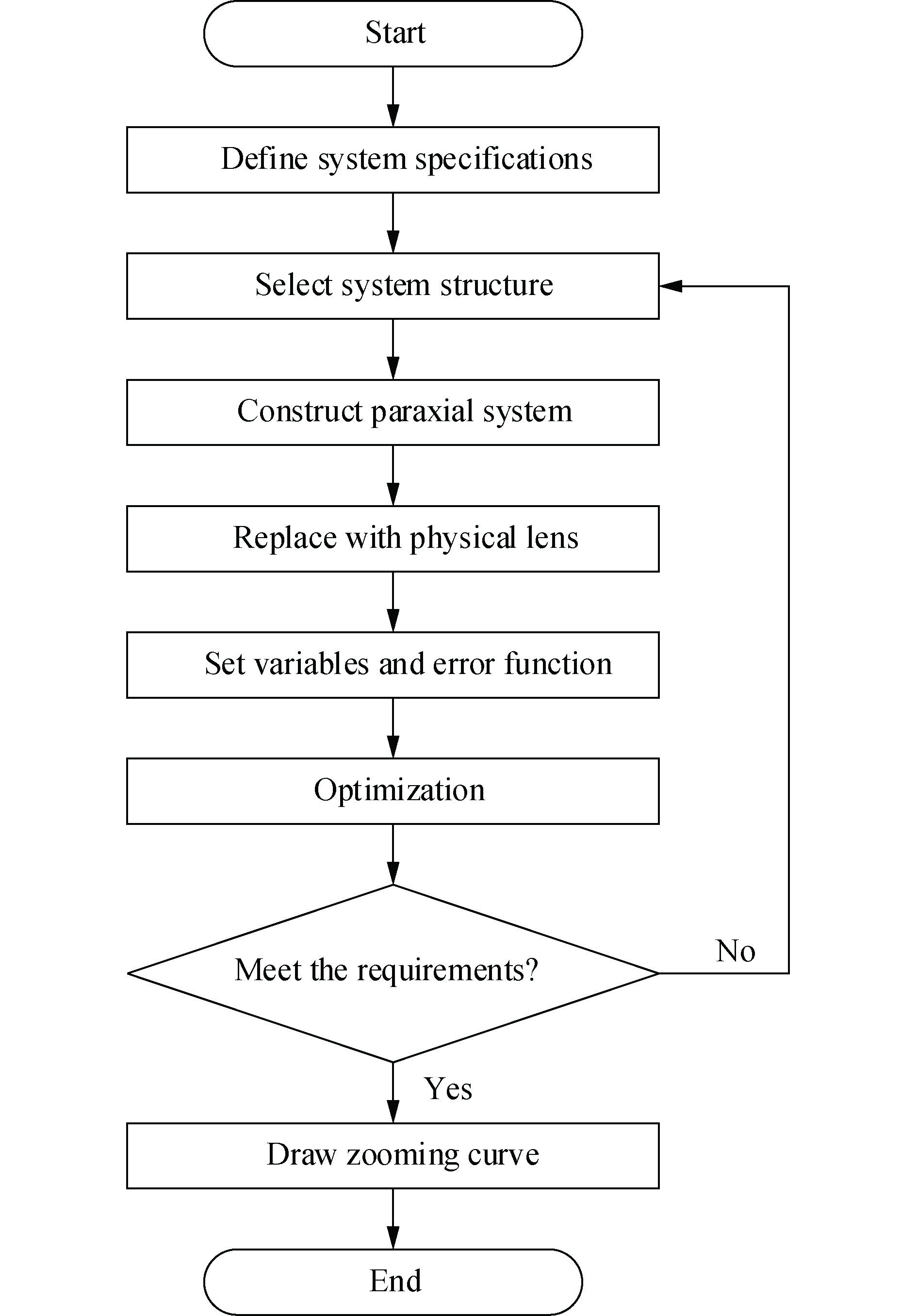
Parameters Value Spectral range Visible spectrum Numerical aperture(NA) 0.05–0.2 Field of view/mm Φ1.70–11.1 Object distance/mm 20 Zoom range 1×–6.5× 1X-3.3XMTF(80 lp/mm) ≥0.3 3.3X-6.5XMTF(60 lp/mm) ≥0.3 根据以上指标要求,选用上述含有3个运动组的5组元变焦光学系统结构形式,按照如图2所示的步骤,并借助光学设计软件进行设计和优化,通过不断调整镜头结构参数和面型参数,最终获得连续变焦偏振视频显微镜光学系统结构,如图3所示。该系统全长220 mm,工作距离为22 mm,后截距为14 mm。系统采用了3组双胶合透镜,根据透镜的光焦度正负,选用高低阿贝数的玻璃材料搭配,有利于校正色差和球差。该结构具有前后工作距离稳定的特点,文中选取系统放大倍数为1×, 2.1×, 3.3×, 4.8×, 6.5×为其典型变焦状态,其基本参数如表3所示。

图 2 光学设计流程图
Figure 2. Optical design flow chart
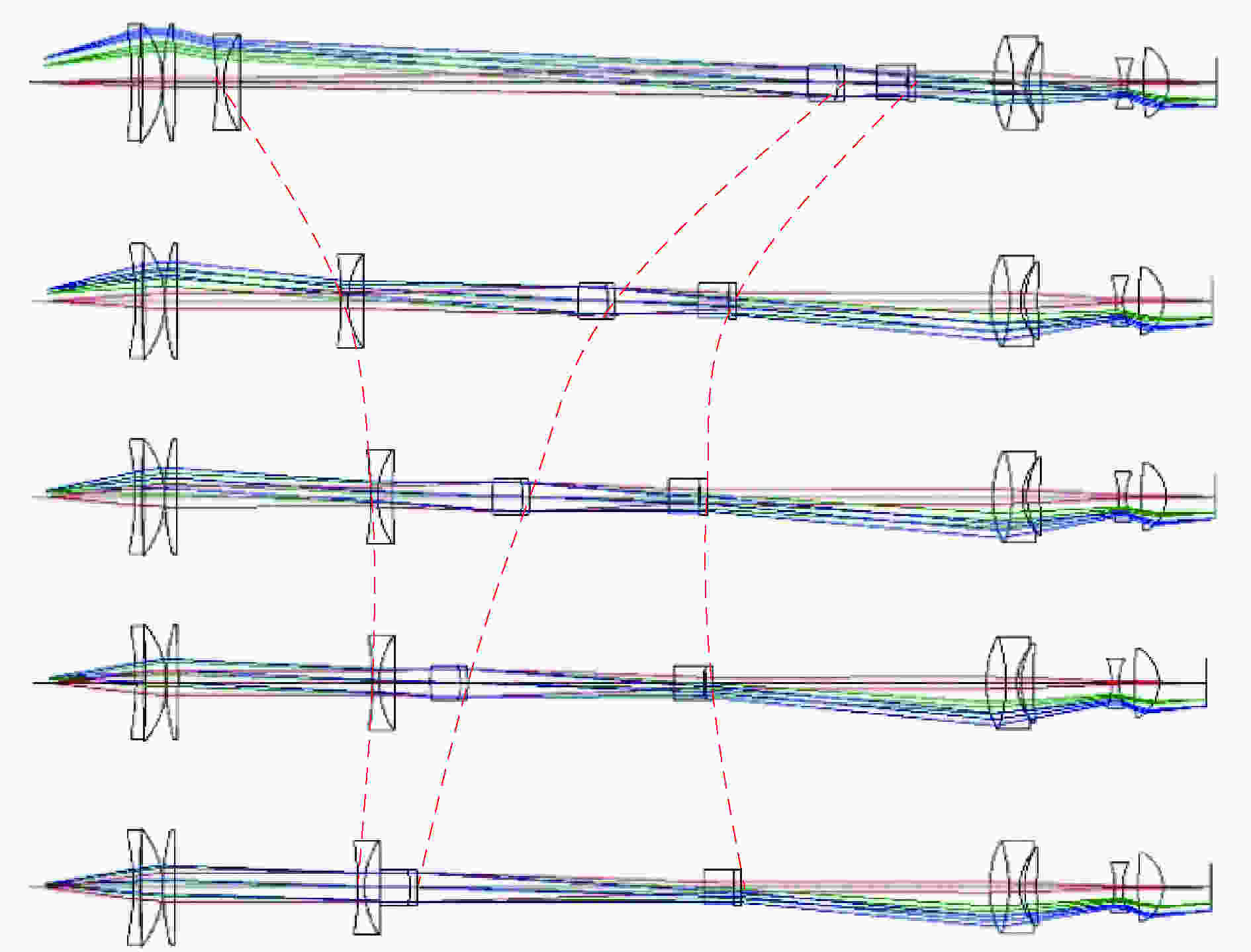
图 3 放大系数为1×, 2.1×, 3.3×, 4.8×, 6.5×时的系统结构图
Figure 3. Optical layouts of 1×, 2.1×, 3.3×, 4.8×, 6.5×
表 3 典型变焦状态的基本参数
Table 3. Basic parameters of typical zoom states
Zoom 1 Zoom 2 Zoom 3 Zoom 4 Zoom 5 Magnification 1× 2.1× 3.3× 4.8× 6.5× Field of view/mm 11.1 5.28 3.36 2.31 1.70 NA 0.05 0.1 0.14 0.17 0.20 图4给出了在5个典型变焦状态下的点列图。所有变
焦状态下的点列图RMS尺寸都小于一个像元尺寸,在使用上述选定探测器时可以达到最大分辨率。 
图 4 放大系数为1×, 2.1×, 3.3×, 4.8×, 6.5×时的点列图
Figure 4. Spot diagrams of 1×, 2.1×, 3.3×, 4.8×, 6.5×
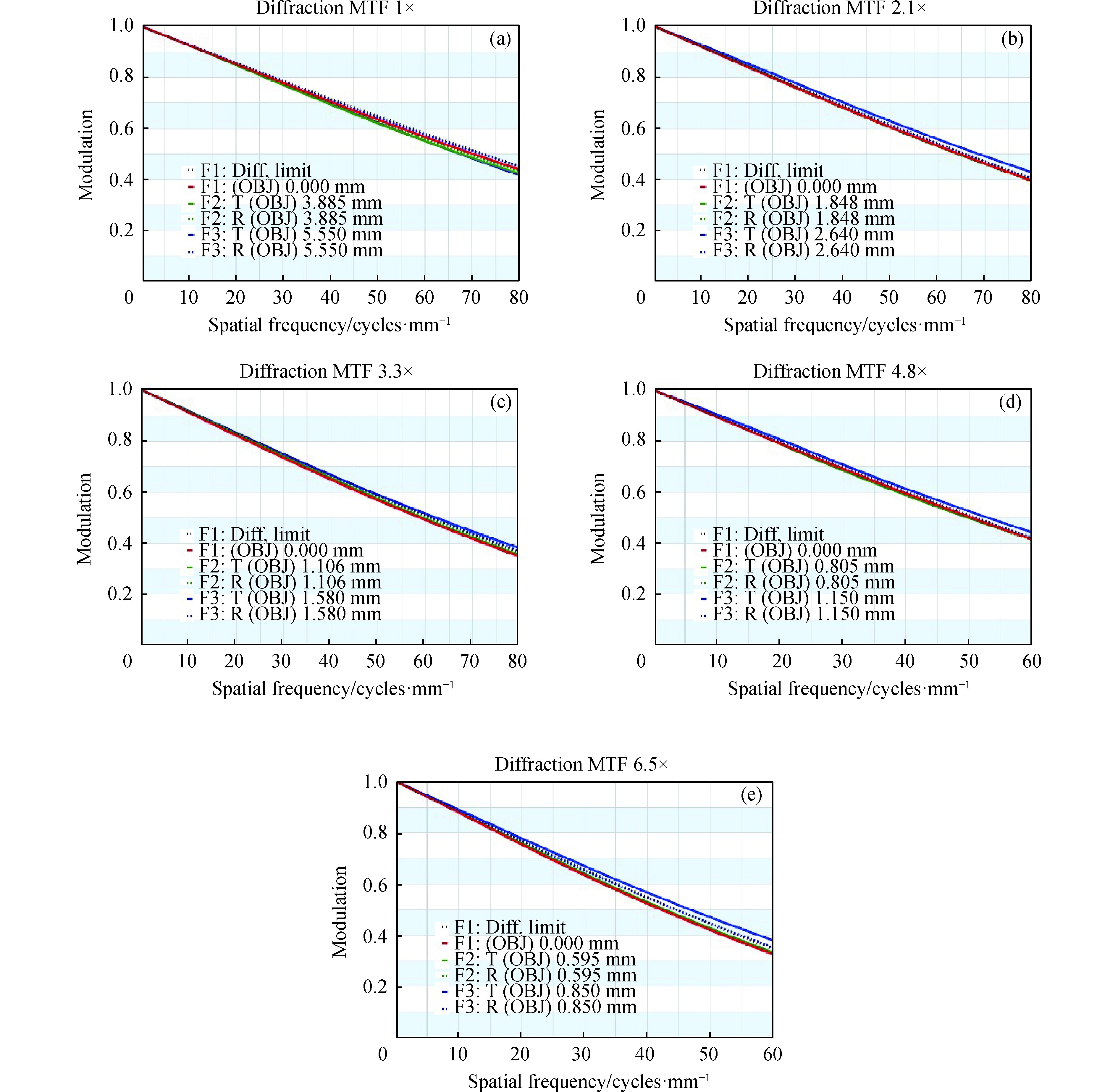
调制传递函数(MTF)反映了系统的成像质量,图5给出了在5个典型变焦状态下的MTF曲线。MTF曲线接近衍射极限,当特征频率在60 lp/mm时,1×~3.3×的MTF值在0.48以上,3.3×~6.5×的MTF值在0.32以上;在80 lp/mm时,1×~3.3×的MTF值也能做到大于0.34以上。由此说明,在不同变焦状态下,系统各个视场像差均衡,成像质量较好,满足系统的成像要求。

图 5 放大系数为1×, 2.1×, 3.3×, 4.8×, 6.5×时的调制传递函数曲线图
Figure 5. MTF plots of 1×, 2.1×, 3.3×, 4.8×, 6.5×
计算上述选取的5个变倍位置下,变倍组、补偿组1和补偿组2的第一面到前固定组最后一面的距离D的取值,如表4所示的凸轮曲线数据表。
表 4 凸轮曲线数据表
Table 4. Zoom CAM curve data table
D/mm Zoom 1 Zoom 2 Zoom 3 Zoom 4 Zoom 5 ZG 9.512 37.303 43.973 44.489 41.4605 CG 1 142.973 91.180 71.612 57.829 46.495 CG 2 158.869 118.685 111.764 113.731 120.246 以系统放大倍率为横坐标,D为纵坐标,拟合得到如图6所示3条变焦曲线[12]。从图中可以看出,凸轮曲线较为平滑,机械加工简单可行。

图 6 变倍组、补偿组1和2的变焦曲线
Figure 6. Zoom curves of zoom group, compensating group 1 and 2
-
针对在低照度环境下,传统显微镜存在的识别难度大、成像对比度低等问题,结合偏振成像技术在低照度环境下的优势,开展了可见光偏振成像显微物镜的研究。结合分焦平面偏振探测器,设计了一款五组元连续变焦偏振视频显微物镜。设计完成后,该物镜全长220 mm,变倍范围为1×−6.5×,物方线视场1.70 ~11.1 mm,后接偏振探测器获得目标的偏振信息。仿真结果表明:系统在各个变焦状态下的成像质量优异,可以获得目标的偏振信息,提高目标的识别概率、观察效率和低照度情况下的成像效果。
Optical design of continuous zoom polarization video microscope
-
摘要: 针对传统显微镜在低照度环境时成像对比度低、识别难度大等问题,提出结合分焦平面偏振成像技术,设计了一款含三个移动组的五组元连续变焦偏振视频显微物镜。该物镜工作在可见光波段,变倍范围为1×−6.5×,物方线视场1.70 ~11.1 mm,全长220 mm,工作距离为22 mm,后截距为14 mm,后接偏振探测器获得目标的偏振信息。经仿真分析,该系统在变焦范围内像面稳定,在各个变焦状态下成像质量接近衍射极限。该系统不仅可以在显示屏上获得目标的不同放大倍率的像,缓解视疲劳,还可以获得目标的偏振信息,提高目标的识别概率、观察效率和低照度情况下的成像效果。Abstract: Aiming at the problems of low imaging contrast and difficult recognition of traditional microscopes in low-illuminance environments, a continuous zoom polarization video microscope objective in combination was designed with division-of-focal-plane polarization imaging technique. The objective lens worked in the visible light band, with a zoom range of 1×−6.5×, an object-line field of view of 1.70−11.1 mm, a total length of 220 mm, a working distance of 22 mm, and image distance of 14 mm. And the system was followed by a polarization detector to obtain the target’s polarization information. After simulation analysis, the image plane was stable in the zoom range, and the imaging quality was close to the diffraction limit in each zoom state. The system can not only obtain images of different magnifications of the target on the electronic display and alleviate visual fatigue, but also obtain the polarization information of the target, improve the recognition probability of the target, the observation efficiency and the imaging quality in the case of low illumination.
-
Key words:
- continuous zoom /
- polarization imaging /
- video microscope /
- optical design
-
图 3 放大系数为1×, 2.1×, 3.3×, 4.8×, 6.5×时的系统结构图
Figure 3. Optical layouts of 1×, 2.1×, 3.3×, 4.8×, 6.5×
图 4 放大系数为1×, 2.1×, 3.3×, 4.8×, 6.5×时的点列图
Figure 4. Spot diagrams of 1×, 2.1×, 3.3×, 4.8×, 6.5×
图 5 放大系数为1×, 2.1×, 3.3×, 4.8×, 6.5×时的调制传递函数曲线图
Figure 5. MTF plots of 1×, 2.1×, 3.3×, 4.8×, 6.5×
表 1 变焦显微物镜代表产品
Table 1. Representative zoom microscope objectives
Company Product Zoom ratio Zoom range Olympus MVX10 10:1 0.63×−6.3× Zeiss Smartzoom 5 10:1 0.5×−5× Zhejiang Sunny Ltd. SZ6Series 6.5:1 0.7×−4.5× Guilin Microtech Ltd. MZDM0745Series 6.4:1 0.7×−4.5×  下载: 导出CSV
表 2 系统主要设计指标
Table 2. Specifications of optical system
Parameters Value Spectral range Visible spectrum Numerical aperture(NA) 0.05–0.2 Field of view/mm Φ1.70–11.1 Object distance/mm 20 Zoom range 1×–6.5× 1X-3.3XMTF(80 lp/mm) ≥0.3 3.3X-6.5XMTF(60 lp/mm) ≥0.3
下载: 导出CSV
表 3 典型变焦状态的基本参数
Table 3. Basic parameters of typical zoom states
Zoom 1 Zoom 2 Zoom 3 Zoom 4 Zoom 5 Magnification 1× 2.1× 3.3× 4.8× 6.5× Field of view/mm 11.1 5.28 3.36 2.31 1.70 NA 0.05 0.1 0.14 0.17 0.20
下载: 导出CSV
表 4 凸轮曲线数据表
Table 4. Zoom CAM curve data table
D/mm Zoom 1 Zoom 2 Zoom 3 Zoom 4 Zoom 5 ZG 9.512 37.303 43.973 44.489 41.4605 CG 1 142.973 91.180 71.612 57.829 46.495 CG 2 158.869 118.685 111.764 113.731 120.246
下载: 导出CSV
-
[1] 张斌. 大视场显微镜的设计[J]. 光学仪器, 2003, 25(4): 81-83. doi: 10.3969/j.issn.1005-5630.2003.04.017 Zhang Bin. Design of wide field-of-view microscope [J]. Optical Instruments, 2003, 25(4): 81-83. (in Chinese) doi: 10.3969/j.issn.1005-5630.2003.04.017 [2] 李晓奇. 超长工作距视频显微镜光学系统设计[D]. 长春: 长春理工大学, 2014. Li Xiaoqi. The optical system design of video microscope with super long working Distance[D]. Changchun: Changchun University of Science and Technology, 2014. (in Chinese) [3] 操超, 廖志远, 白瑜, 等. 一种新型复合变焦光学系统[J]. 光学学报, 2017, 37(11): 1108001. doi: 10.3788/AOS201737.1108001 Cao Chao, Liao Zhiyuan, Bai Yu, et al. A New compound zoom optical system [J]. Acta Optica Sinica, 2017, 37(11): 1108001. (in Chinese) doi: 10.3788/AOS201737.1108001 [4] Li Lei, Wang Di, Liu Chao, et al. Zoom microscope objective using electrowetting lenses [J]. Opt Express, 2016, 24(3): 2931-2940. doi: 10.1364/OE.24.002931 [5] Pierangelo Angelo, Nazac Andre, Benali Abdelali, et al. Polarimetric imaging of uterine cervix: a case study [J]. Opt Express, 2013, 21(12): 14120-14130. doi: 10.1364/OE.21.014120 [6] Scott Tyo, Goldstein Dennis, Chenault David, et al. Review of passive imaging polarimetry for remote sensing applications [J]. Appl Optics, 2006, 45(22): 5453-5469. doi: 10.1364/AO.45.005453 [7] 李淑军, 姜会林, 朱京平, 等. 偏振成像探测技术发展现状及关键技术[J]. 中国光学, 2013, 6(6): 803-809. Li Shujun, Jiang Huilin, Zhu Jingping, at al. Development status and key technologies of polarization imaging detection [J]. Chinese Optics, 2013, 6(6): 803-809. (in Chinese) [8] 李佳昕, 白廷柱, 崔志刚, 等. 像素偏振成像系统的耦合实现[J]. 红外与激光工程, 2019, 48(9): 0925001. doi: 10.3788/IRLA201948.0925001 Li Jiaxin, Bai Tingzhu, Cui Zhigang, et al. Coupling implementation of pixel polarization imaging system [J]. Infrared and Laser Engineering, 2019, 48(9): 0925001. (in Chinese) doi: 10.3788/IRLA201948.0925001 [9] 彭勇, 冯斌, 史泽林, 等. 微偏振片阵列成像的非均匀校正研究[J]. 红外与激光工程, 2017, 46(4): 0404004. doi: 10.3788/IRLA201746.0404004 Peng Yong, Feng Bin, Shi Zelin, et al. Nonuniformity correction in polarization imaging obtained with integrated microgrid polarimeters [J]. Infrared and Laser Engineering, 2017, 46(4): 0404004. (in Chinese) doi: 10.3788/IRLA201746.0404004 [10] Sun M, He H, Zeng N, et al. Characterizing the microstructures of biological tissues using Mueller matrix and transformed polarization parameters [J]. Biomedical Optics Express, 2014, 5(12): 4223. doi: 10.1364/BOE.5.004223 [11] Maruyama Yasushi, Terada Takashi, Yamazaki Tomohiro, et al. 3.2-MP back-illuminated polarization image sensor with four-directional air-gap wire grid and 2.5-μm pixel [J]. IEEE Transactions on Electron Devices, 2018, 65(6): 2544-2551. doi: 10.1109/TED.2018.2829190 [12] 侯国柱, 吕丽军. 五组元变焦镜头凸轮曲线设计[J]. 红外技术, 2018, 40(5): 81-84. Hou Guozhu, L Lijun. Cam curve design of five component zoom lens [J]. Infrared Technology, 2018, 40(5): 81-84. (in Chinese) [13] 王靖锋. 变焦距光学系统小型化技术研究[D]. 长春: 长春理工大学, 2019. Wang Jingfeng. Research on miniaturization technology of zoom optical system[D]. Changchun: Changchun University of Science and Technology, 2019. (in Chinese) -

 点击查看大图

计量
- 文章访问数: 1241
- HTML全文浏览量: 640
- PDF下载量: 67
- 被引次数: 0


