


-
具有调焦功能的光学系统在空间探测领域中有着重要的应用需求。例如航天飞行器上的光学载荷因为空间环境气压和温度的变化、发射过程中的剧烈冲击等力学环境因素影响,存在离焦的现象[1-3],尤其是光学监视任务需求中,最佳成像位置随监控目标空间位置的变化而变化,对于固定像面的定焦光学系统有着不可忽视的离焦量。离焦产生的模糊是获取清晰图像的重要障碍之一。
为了实现光学系统对不同物距目标的清晰成像,提升在复杂环境的适应性能力,光学系统的设计方案需要重点考虑内调焦的实现方法。李丹等[4]设计了一种二元光学内调焦望远物镜的光学系统,焦距为245 mm,全视场为1.5°,利用二元透镜独特的色散特性校正系统的色差,实现无穷远到1.5 m物距调焦范围。刘智颖等[5]设计了一种宽光谱内调焦的光学系统,焦距为90 mm,波段范围为420~900 nm,全视场为1.6°,实现了200 m~200 km物距调焦范围。以上光学系统采用调焦透镜沿光轴方向移动的方法,实现内调焦功能,同时也存在着系统像差变化的问题。因此在长焦距内调焦光学系统中视场角相对较小,较大视场的像差矫正也是内调焦优化方案中有待解决的关键问题之一。
光学自由曲面一般无法用球面或是非球面系数来表达[6-7],具有较高的自由度和较强的像差矫正能力,但对加工精度提出了较为严格的要求[8]。2010年后,随着超精密加工和检测技术的发展[9],自由曲面在成像光学应用的潜力不断被挖掘。近年来,Zou Y等[10]成功研制出一款基于自由曲面透镜组成像的内窥镜样机,焦距变化范围在4.9~7.4 mm,通光口径为2 mm。Petsch S等[11]结合LCE人工肌肉驱动器和自由曲面透镜对,设计了一种微小型可见光范围成像的光学系统,系统焦距变化范围为25.1~28.4 mm,通光口径为2.5 mm。自由曲面变焦透镜的发展趋势偏向微小型,在长焦距较大孔径光学系统中的应用仍有待发展。
文中设计了一种基于自由曲面横向偏移的内调焦光学系统,焦距为100 mm,波段范围为450~700 nm,全视场为12°,相对口径为1/5.6,物距调焦范围为无穷远到1.5 m。该光学系统通过自由曲面透镜组垂轴移动的方法调制入射光波的复振幅,实现较大口径的内调焦功能。
-
自由曲面面型结构可以采用XY多项式描述,其表达式如公式(1)所示:
$${\textit{z}} = \dfrac{{{{c}}{r^{\rm{2}}}}}{{{\rm{1 + }}\sqrt {{{1 - (1 + k)}}{{{c}}^{\rm{2}}}{r^{\rm{2}}}} }}{\rm{ + }}\sum\limits_{{{j = 1}}}^{{N}} {{{{A}}_{{j}}}{x^{{m}}}{y^{{n}}}} $$ (1) 式中:
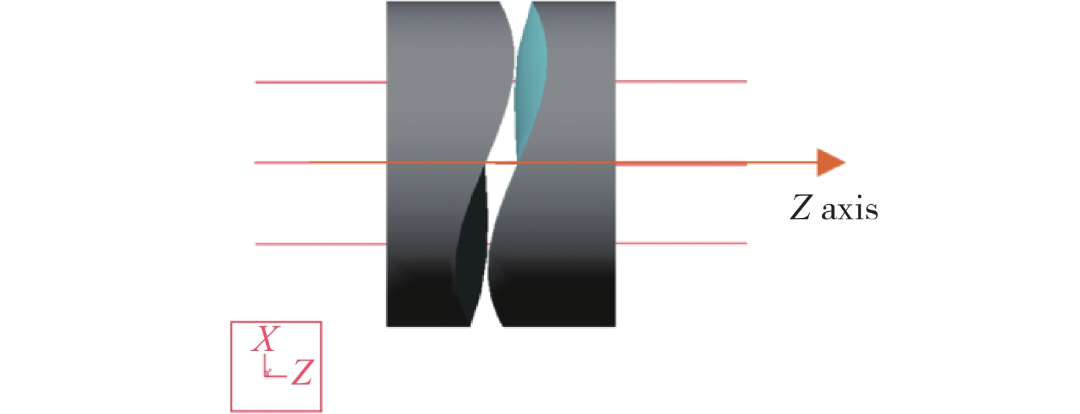
$(x,y) $ 表示自由曲面的孔径坐标;${\textit{z}}$ 为表面在对应坐标点$(x,y) $ 的厚度;c为表面顶点曲率;k为二次曲面常数;$r$ 为径向半径,有$r = \sqrt {{x^2} + {y^2}} $ ;m为$x$ 的级数;n为$y$ 的级数;N为多项式的项数;${{{A}}_{{j}}}$ 为多项式第$j$ 项数,有$ {{j = }}\dfrac{{{{{{(m + n)}}}^{\rm{2}}}{{ + m + 3n}}}}{{\rm{2}}}{{ + 1}}$ 。自由曲面透镜组由4个面构成,其中2个为平面,位于透镜组外侧表面,另外2个表面为自由曲面,位于透镜组内侧表面,2个自由曲面的空气间隔很小,自由曲面透镜组结构模型如图1所示。

图 1 自由曲面透镜组模型
Figure 1. Model of the freeform lens
光线沿z轴方向自左向右传播。当自由曲面垂轴偏移量
$\delta = 0$ 时,透镜组对光学系统的光焦度没有贡献。因此自由曲面surf1和surf2面型结构相同,其数学表达式用公式(2)进行描述:$$\begin{array}{l} {\rm{surf1\!\!:}}{{{t}}_{\rm{1}}}{\rm{(}}x,y{{) = C + }}\dfrac{{{{c}}{r^{\rm{2}}}}}{{{\rm{1 + }}\sqrt {{{1 - (1 + k)}}{{{c}}^{\rm{2}}}{r^{\rm{2}}}} }}{\rm{ + }}\displaystyle\sum\limits_{{{j = 1}}}^{{N}} {{{{A}}_{{j}}}{x^{{m}}}{y^{{n}}}} \\ {\rm{surf2\!\!:}}{{{t}}_{\rm{2}}}{\rm{(}}x',y'{{) = C - }}\dfrac{{{{c}}{r^{\rm{2}}}}}{{{\rm{1 + }}\sqrt {{{1 - (1 + k)}}{{{c}}^{\rm{2}}}{r^{\rm{2}}}} }}{\rm{ - }}\displaystyle\sum\limits_{{{j = 1}}}^{{N}} {{{{A}}_{{j}}}x^{'{{m}}}y^{'{{n}}}} \\ \end{array} $$ (2) 式中:C为常数,表示自由曲面透镜的顶点厚度;
$(x,y)$ 是以自由曲面surf1的顶点为原点的坐标;$(x',y')$ 是以自由曲面surf2的顶点为原点的坐标。 -
当透镜组中的自由曲面surf1和surf2相对垂轴偏移量为
$\delta $ 时,透镜组的厚度随之发生了变化。假设透镜组沿$x$ 方向偏移,规定沿正$x$ 方向移动$\delta > 0$ 时,由于透镜组中两块自由曲面透镜间的空气间隔很小,可忽略光线在自由曲面surf1和surf2传播过程中空间坐标的变化,则透镜组的厚度可以描述为:$$\begin{split} T(x,y,\delta ) =& {t_1}(x + \delta ,y) + {t_2}(x - \delta ,y)= \\ & {{2C}} + \displaystyle\sum\limits_{{{j}} = 1}^{{N}} {{{{A}}_{{j}}}[{{(x + \delta )}^{{m}}}{y^{{n}}} - {{(x - \delta )}^{{m}}}{y^{{n}}}]} \\ \end{split} $$ (3) 当平行光线经过这组自由曲面透镜组后,相位
$\varphi $ 变化的表达式为:$$ \begin{split} \varphi (x,y,\delta ) =\dfrac{{{{2\pi (}}{{{n}}_{{\lambda }}}{{ - 1)}}}}{{{\lambda }}}\left\{ {{{2C + }}\sum\limits_{{{j = 1}}}^{{N}} {{{{A}}_{{j}}}[{{(x{{ + }}\delta )}^{{m}}}{y^{{n}}}{{ - }}{{(x{{ - }}\delta )}^{{m}}}{y^{{n}}}]} } \right\} \\ \end{split} $$ (4) 式中:
${\rm{\lambda }}$ 为通过透镜组的波长;${{{n}}_{\rm{\lambda }}}$ 为透镜材料的折射率。从公式(4)中提炼出相位变化与
${x^2}$ 和${y^2}$ 相关的项,并重新构建一个相位函数${\varphi _f}({x^2},{y^2},\delta )$ ,表达式如公式(5)所示:$$\begin{split} {\varphi _f}\left( {{x^2},{y^2},\delta } \right) =&\dfrac{{{{2\pi }}}}{{{\lambda }}}\left( {{{{n}}_{{\lambda }}}{{ - 1}}} \right)\displaystyle\sum\limits_{{{m = 3}}}^{{{N'}}} {{{{A}}_{{{j1}}}}{{C}}_{{m}}^{{2}}{x^2}[{\delta ^{{{m - 2}}}}{{ - }}{{\left( {{{ - }}\delta } \right)}^{{{m - 2}}}}]} + \\ &\dfrac{{{{2\pi }}}}{{{\lambda }}}\left( {{{{n}}_{{\lambda }}}{{ - 1}}} \right)\displaystyle\sum\limits_{{{m = 1}}}^{{{N}}'} {{{{A}}_{{{j2}}}}[{\delta ^{{m}}}{{ - }}{{\left( {{{ - }}\delta } \right)}^{{m}}}]{y^2}} \\ \end{split} $$ (5) 式中:m表示
$x$ 的级数;${{N'}}$ 表示$x$ 幂的最大值;${{C}}_{{m}}^{{2}}$ 为组合排列系数;${{{A}}_{{{j1}}}}$ 表示自由曲面XY多项式第${{j1}}$ 项的系数,且有$ {{j1=}}\dfrac{{{m}}^{{2}}{{+m+2}}}{{2}}{{(m\geqslant 3)}}$ ;${{{A}}_{{{j2}}}}$ 表示自由曲面XY多项式第${{j2}}$ 项的系数,且有$ {{j2=}}\dfrac{{{m}}^{{2}}{{+5m+12}}}{{2}}{{(m\geqslant 1)}}$ 。取${{N' = 3}}$ 进行详细分析,公式(5)可简化为:$$\begin{split} {\varphi _f}({x^2},{y^2},\delta ) =& \dfrac{{{{2\pi }}}}{{{\lambda }}}\left( {{{{n}}_{{\lambda }}}{{ - 1}}} \right)\left( {6{{{A}}_{{7}}}\delta {x^2}{{ + 2}}{{{A}}_{{9}}}\delta {y^2}{{ + }}2{{{A}}_{{{18}}}}{\delta ^3}{y^2}} \right) \\ \end{split} $$ (6) 式中:
${{{A}}_{{7}}}$ 、${{{A}}_{{9}}}$ 、${{{A}}_{{{18}}}}$ 表示自由曲面XY多项式第7、9、18项的系数。分析公式(6)可得,式中第一项和第二项与垂轴偏移量$\delta $ 成线性关系,当${{{A}}_{{7}}} = {{{A}}_{{9}}}{{/3}}$ ,${{{A}}_{{{18}}}} = $ $ {{0}}$ 时,相位${\varphi _f}({x^2},{y^2},\delta ) $ 为:$${\varphi _f}({x^2},{y^2},\delta ) = \frac{{{{2\pi }}}}{{{\lambda }}}\left( {{{{n}}_{{\lambda }}}{{ - 1}}} \right){{2}}{{{A}}_{{9}}}\delta \left( {{x^2} + {y^2}} \right)$$ (7) 已知球面薄透镜相位变换为:
$${\varphi _{sp}}({x_1},{y_1}) = \frac{{{\rm{2\pi }}}}{{\rm{\lambda }}}\frac{{{x_1}^2 + {y_1}^2}}{{2{f_{sp}}}}$$ (8) 式中:
$({x_1},{y_1})$ 为常规球面透镜的孔径坐标;$\lambda $ 为波长;${f_{sp}}$ 为球面透镜的焦距。结合公式(7)和公式(8)得到自由曲面透镜组焦距${f_{{\rm{freeform}}}}$ 的表达式:$${f_{{\rm{freeform}}}}{\rm{ = }}\frac{1}{{4\delta {{{A}}_{\rm{9}}}\left( {{{{n}}_{{\lambda }}} - {\rm{1}}} \right)}}$$ (9) 根据公式(9)可知,自由曲面透镜组焦距
${f_{{\rm{freeform}}}}$ 分别与垂轴偏移量$\delta $ 、多项式第9项系数${{A}}_{\rm{9}}$ 、透镜材料折射率${{n}}_{\rm{\lambda }}$ 成反比。其中折射率${{n}}_{\rm{\lambda }}$ 与波长相关,当透镜材料的阿贝常数越小,自由曲面透镜组的色散越明显,不利于光学系统二级色差的矫正。多项式系数${{A}}_{\rm{9}}$ 与自由曲面的面型平缓程度相关,${{A}}_{\rm{9}}$ 越大,自由曲面的面型越陡峭,不利于自由曲面的超精密加工和大通光口径的设计。当${{A}}_{\rm{9}}>$ 0时,讨论垂轴偏移量$\delta $ 以下3种情况,并结合光学设计软件得到仿真结果,如图2所示。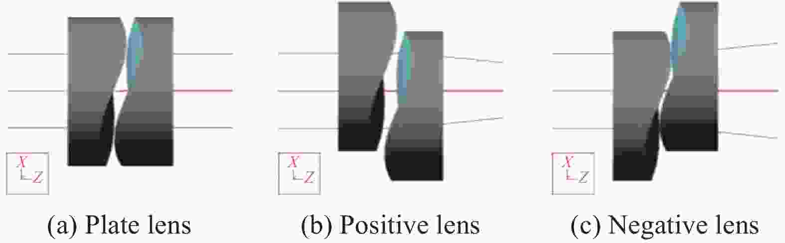
图 2 相对偏移量δ对透镜的影响
Figure 2. Effect of the lateral shift δ on lens
(1)当相对偏移量
$\delta {\rm{ = }}0$ 时,透镜组表现为平板效果,如图2(a)所示;(2)当相对偏移量
$\delta > 0$ 时,透镜组表现为正透镜效果,如图2(b)所示。结合公式(9)分析得到,随着垂轴偏移量$\delta $ 的增加,入射光波调制后的会聚效果越明显;(3)当相对偏移量
$\delta < 0$ 时,透镜组表现为负透镜效果,如图2(c)所示。结合公式(9)分析得到,随着垂轴偏移量$\delta $ 的减小(绝对值增加),入射光波调制后的发散效果越明显。 -
在内调焦光学系统中,以自由曲面透镜组作为调焦镜,结合不同物距目标成像和像距扰动的成像情况建立数学模型,如公式(10)所示:
$$\frac{{\rm{1}}}{{{{l' + }}\Delta l'}}{\rm{ - }}\frac{{\rm{1}}}{l} = \frac{{{f_{{\rm{freeform}}}}{\rm{ + }}{{{f}}_{\rm{0}}}{{' - d}}}}{{{{{f}}_{\rm{0}}}{{'}}{f_{{\rm{freeform}}}}}}$$ (10) 式中:
${f_0}'$ 为常数,表示光学系统焦距(不含自由曲面透镜组);${f_{{\rm{freeform}}}}$ 为变量,表示自由曲面透镜组焦距;$d$ 为常数,表示光学系统(不含自由曲面透镜组)主平面和自由曲面透镜组主平面的距离;$l'$ 为常数,表示对应无穷远物距的像距;$\Delta l'$ 为变量,表示空间环境因素造成的离焦量;$l$ 为变量,表示成像目标的物距。公式(10)中变量${f_{{\rm{freeform}}}}$ 作为调节组件,实现对变量$\Delta l'$ 和$l$ 的补偿,使光学系统处于准确对焦位置。在自由曲面透镜的材料和面型确定的条件下,${f_{{\rm{freeform}}}}$ 中$\delta $ 为唯一补偿变量。以焦距为100 mm、相对孔径为1/5.6、视场角
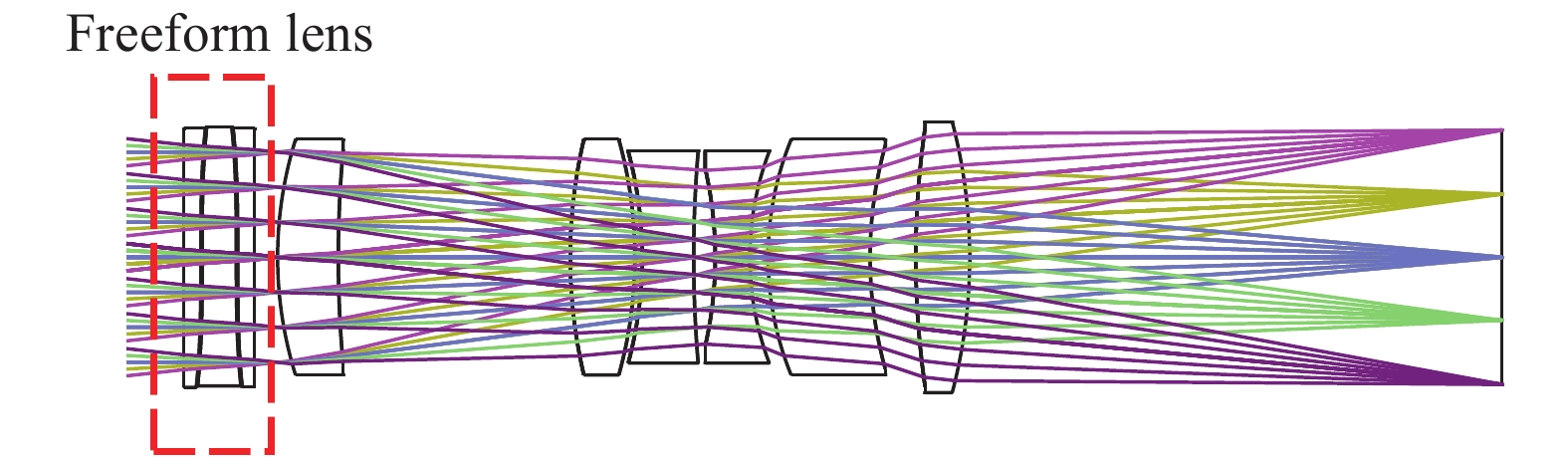
$2\omega $ 为12°、光谱范围为450~700 nm为约束条件,通过delano图解法求解得到一个光学系统初始结构。结合公式(10)可知,在初始结构前加入自由曲面透镜组,并且使得初始结构和自由曲面透镜的主平面距离${{d}}$ 较小,充分利用自由曲面的变焦特性补偿像距和物距的变化。由于光学系统装配需要一定的间隙,因此选取${{d = 2}}\;{\rm{mm}}$ 。自由曲面透镜的光学材料选择折射率较大且阿贝常数较大的重磷冕玻璃,如H-ZPK7。自由曲面透镜的面型考虑口径问题,选取${{{A}}_{\rm{9}}} = $ $ {\rm{0}}{\rm{.000\;9}}$ 。物距调焦范围$l$ 为无穷远到1.5 m,环境因素引起的离焦量$\Delta l'$ 是不确定值,通过环境温度(Temperature,$T$ )和大气压强(Atmosphere pressure,${P_{{\rm{atm}}}}$ )对系统的影响定性分析,选取温度范围为−100~100 ℃,大气压强为0~1 atm(1 atm=1.013×10⁵ Pa)。经过光学软件优化后得到最终的内调焦光学系统如图3所示,具体参数指标如表1所示。
图 3 内调焦光学系统
Figure 3. Schematic diagram of internal focusing optical system
表 1 内调焦光学系统参数指标
Table 1. Specific parameters of internal focusing optical system
Parameter Value Focal length/mm 100 F number 5.6 Field of view/(°) 12 Wavelength/nm 450-700 Total length/mm 115 Size of pixel/μm2 5.5×5.5 Object length/m 1.5-Infinity Temperature/℃ −100~100 Atmosphere/atm 0-1 如图3所示,光学系统中有1组自由曲面透镜组和6片球面透镜构成,其中自由曲面透镜组由3片带有自由曲面的透镜组成。光学系统的面型结构和材料特性如表2所示。
表 2 自由曲面透镜的参数特性
Table 2. Specific parameters of freeform lens
Title Type A9 Radius Thickness Materials Lens 1 Sphere - Infinity 1.5 H-ZPK7 XY polynomial 0.0009 Infinity 0.1 Lens 2 XY polynomial 0.0009 Infinity 3 H-ZPK7 XY polynomial −0.0009 Infinity 0.1 Lens 3 XY polynomial −0.0009 Infinity 1.5 H-ZPK7 Sphere - Infinity 2 Lens 4 Sphere - 32.74 5.30 H-ZK11 Sphere - 97.91 20.26 Lens 5 Sphere - 42.76 5.64 H-ZK11 Sphere - −36.33 0.64 Lens 6 Sphere - −33.70 4.50 H-ZF3 Sphere - 103.82 1.88 Lens 7 Sphere - −32.88 3.02 H-ZF3 Sphere - 24.68 1.59 Lens 8 Sphere - 25.87 8.91 H-ZK9B Sphere - 34.59 3.99 Lens 9 Sphere - 74.32 4.71 H-ZF12 Sphere - −44.04 46.37 -
自由曲面透镜组由于自由曲面不具有旋转对称性,在成像性能分析的过程中,重点分析中心视场、0.5视场和全视场的4个方向(
${{ + X}}$ 方向,${{ - X}}$ 方向,${{ + Y}}$ 方向,${{ - Y}}$ 方向)的成像质量。 -
物距
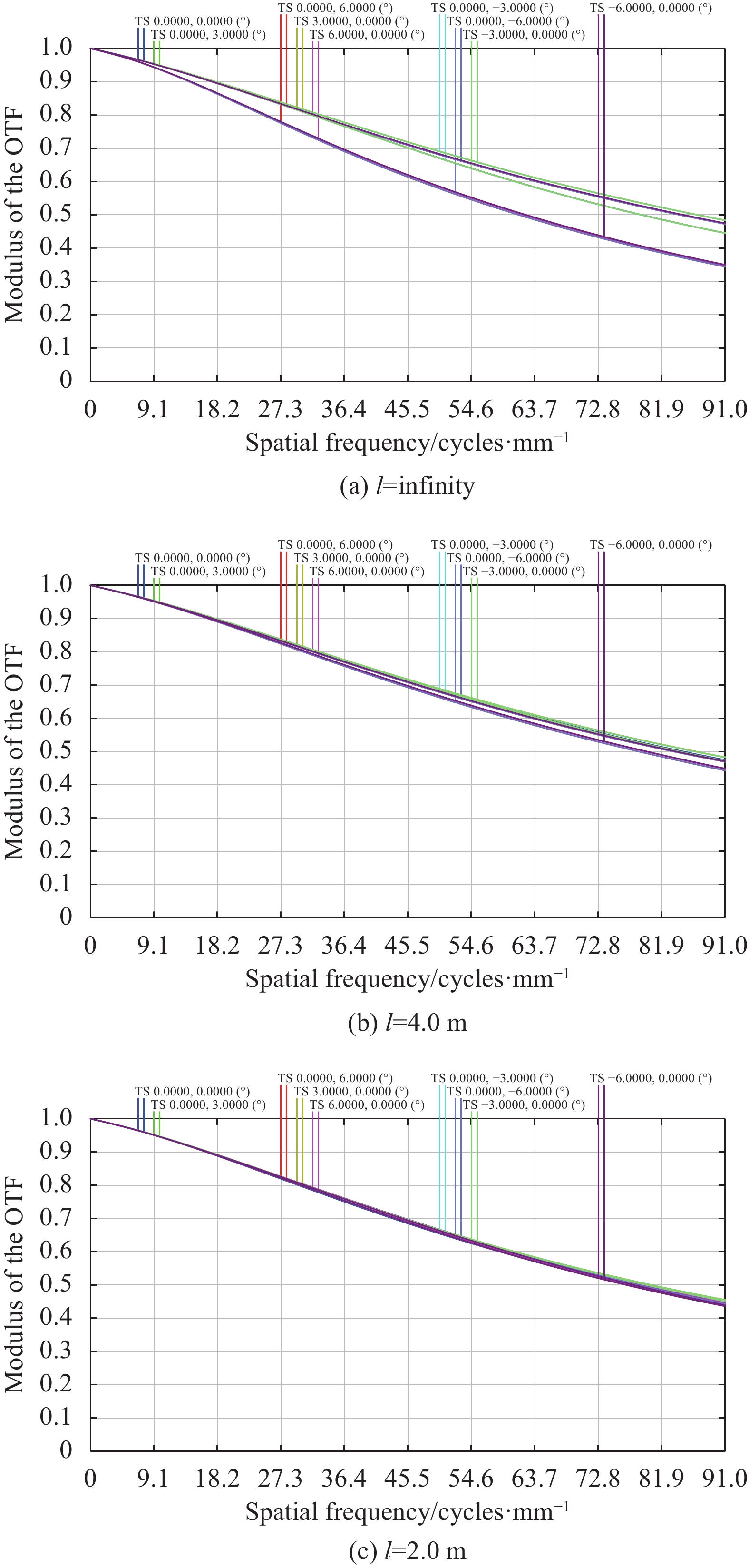
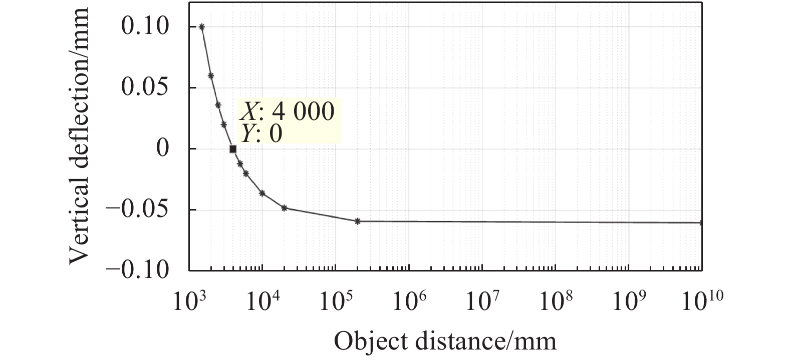
$l$ 的变化范围为无穷远到1.5 m,选取物距$l$ 分别为无穷远、4 m、2 m和1.5 m进行成像分析。光学系统处于温度为20 ℃、大气压强为1 atm的空间环境中。图4所示为光学系统的调制传递函数(MTF)曲线,在1.5 m到无穷远物距范围内表现出良好的成像性能,在奈奎斯特频率91 lp/mm处的中心视场MTF大于0.4,全视场范围的MTF大于0.3,满足成像要求。图5所示为自由曲面透镜组在不同物距成像条件下的垂轴补偿量$\delta $ 变化曲线,曲线具有单调性,符合自动对焦算法的应用环境。当垂轴补偿量$\delta = 0\;{\rm{mm}}$ 时,对应的物距$l = 4\;{\rm{m}}$ ,该状态为光学系统的初始状态。在1.5 m到无穷远物距成像范围内,垂直于光轴的最大补偿量为0.1 mm。结合图4和图5分析可得,随着成像物距偏离初始状态物距$l = 4\;{\rm{m}}$ 越远,自由曲面透镜组的垂轴补偿量$\delta $ 的绝对值越大,光学系统MTF下降越明显。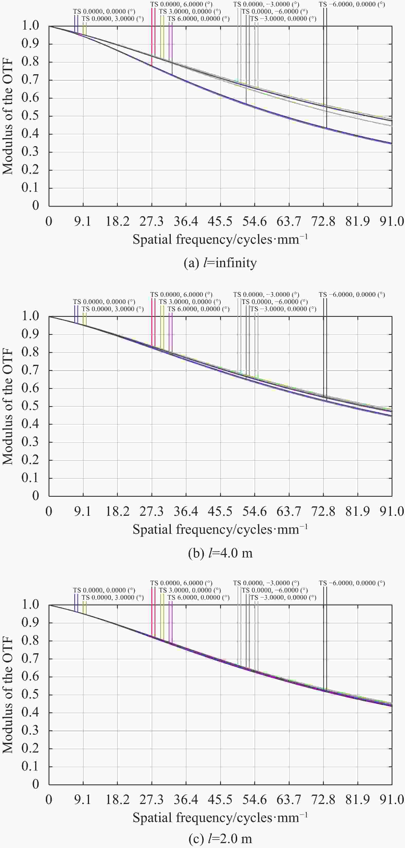
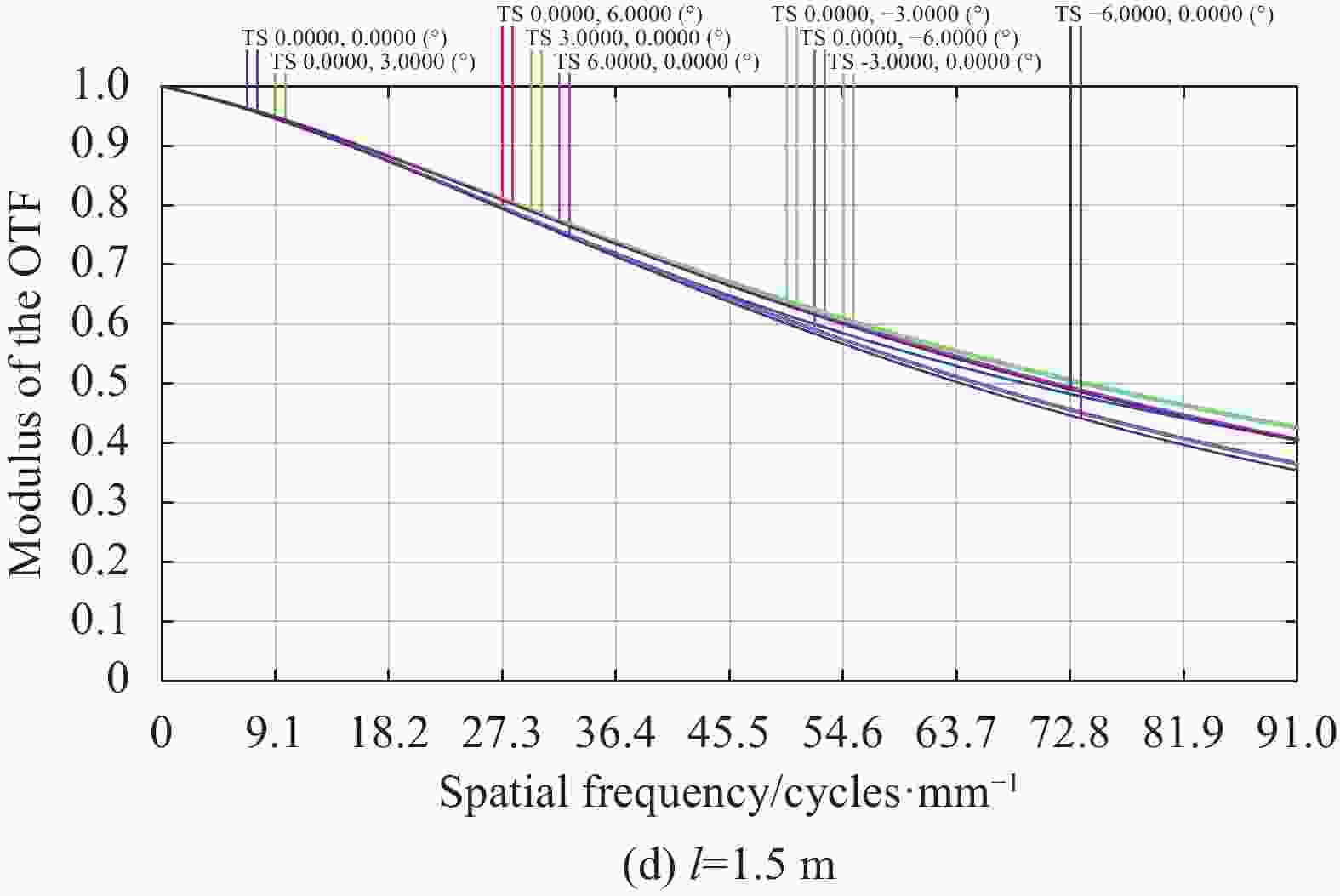
图 4 不同物距情况下的光学系统MTF曲线图
Figure 4. MTF of optical system with different object distance

图 5 不同物距时的垂轴偏移量
Figure 5. Displacement of vertical deflection with different object distance
-
环境因素引起的离焦量
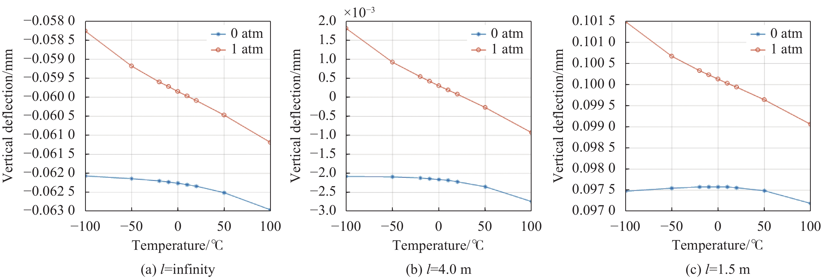
$\Delta l'$ 是不确定值,通过预设环境温度和大气压强变化范围对系统进行分析,温度范围为−100~100 ℃,大气压强为0~1 atm。光学系统的初始状态为垂轴偏移量$\delta = 0\;{\rm{mm}}$ ,对应的物距为$l = 4\;{\rm{m}}$ ,物距无穷远和1.5 m为光学系统的极限成像位置。因此对物距为无穷远、4 m和1.5 m进行空间环境适应性分析。图6所示为无穷远、4 m和1.5 m物距时自由曲面透镜组的垂轴补偿量$\delta $ 和温度、大气压强的曲线图。图中横坐标表示温度变化范围,纵坐标为自由曲面透镜组的垂轴补偿量,带“*”的曲线表示光学系统在0 atm环境中,带“o”的曲线表示光学系统在1 atm环境中。由图可知,无穷远物距成像条件下,温度$ T=$ 100 ℃和大气压强${P_{{\rm{atm}}}} = 0\;{\rm{atm}}$ 的空间环境有最大偏移量$\delta = {\rm{0}}{\rm{.063}}$ (沿X轴负方向);4 m物距成像条件下,温度$ T={100}$ ℃和大气压强${P_{{\rm{atm}}}} = 0\;{\rm{atm}}$ 的空间环境有最大偏移量$\delta = 0.002\;8$ (沿X轴负方向);1.5 m物距成像条件下,温度$ T=-100$ ℃和大气压强${P_{{\rm{atm}}}} = 1\;{\rm{atm}}$ 的空间环境有最大偏移量$\delta = 0.101\;5$ (沿X轴正方向)。图7所示为不同物距在最大偏移量的条件下,光学系统的MTF曲线图。由图可知,光学系统的MTF全视场范围大于0.3,满足成像要求,具有良好的空间适应性能力。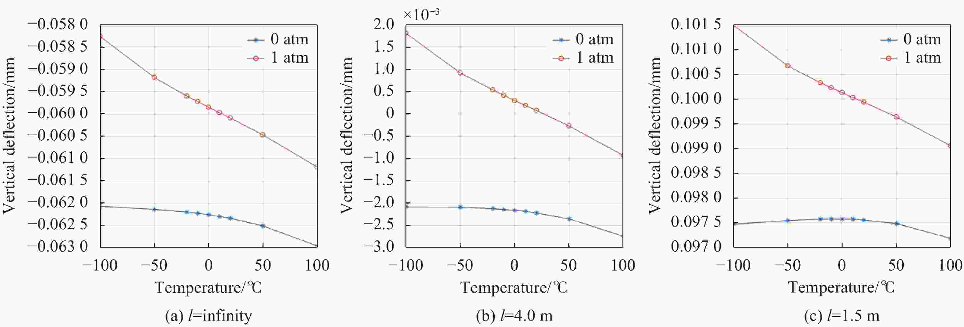
图 6 不同像距时的补偿量
Figure 6. Amount of compensation at different image distance
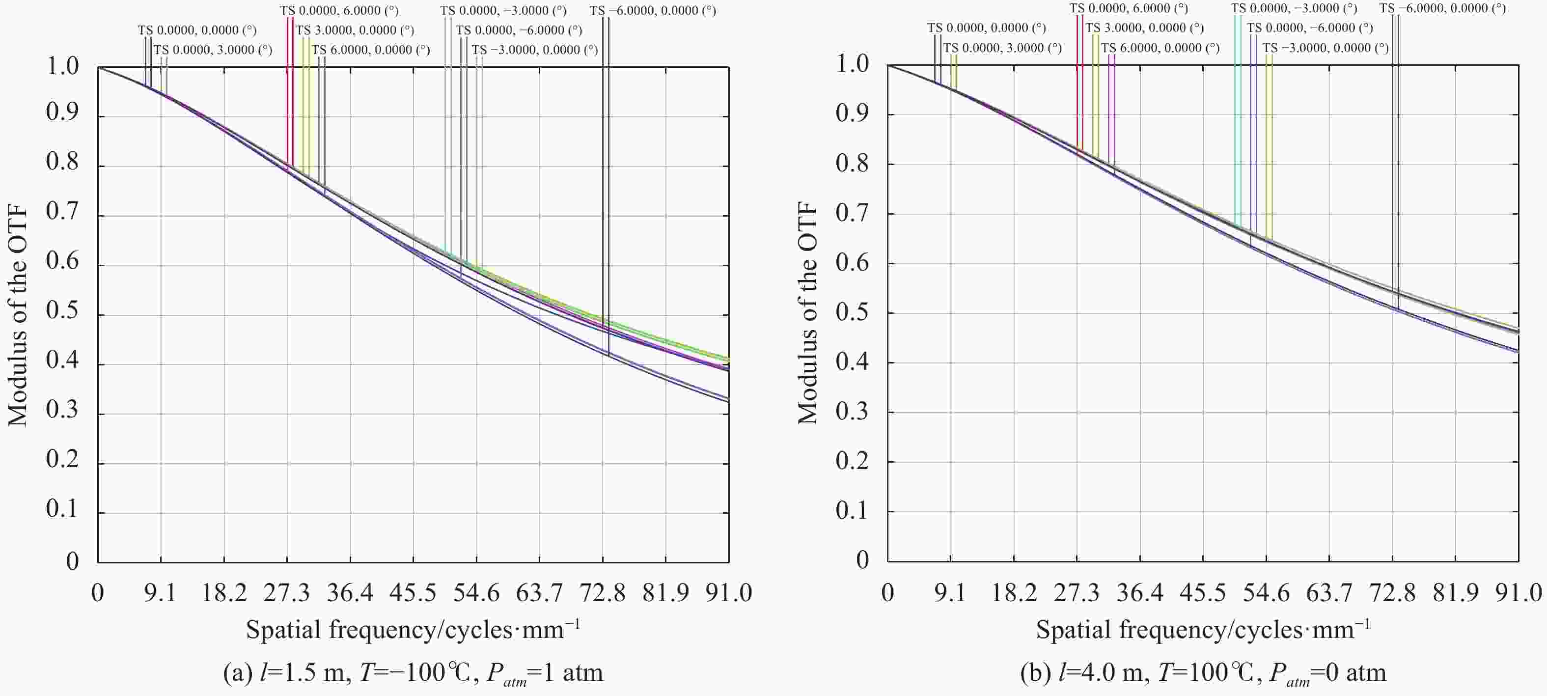
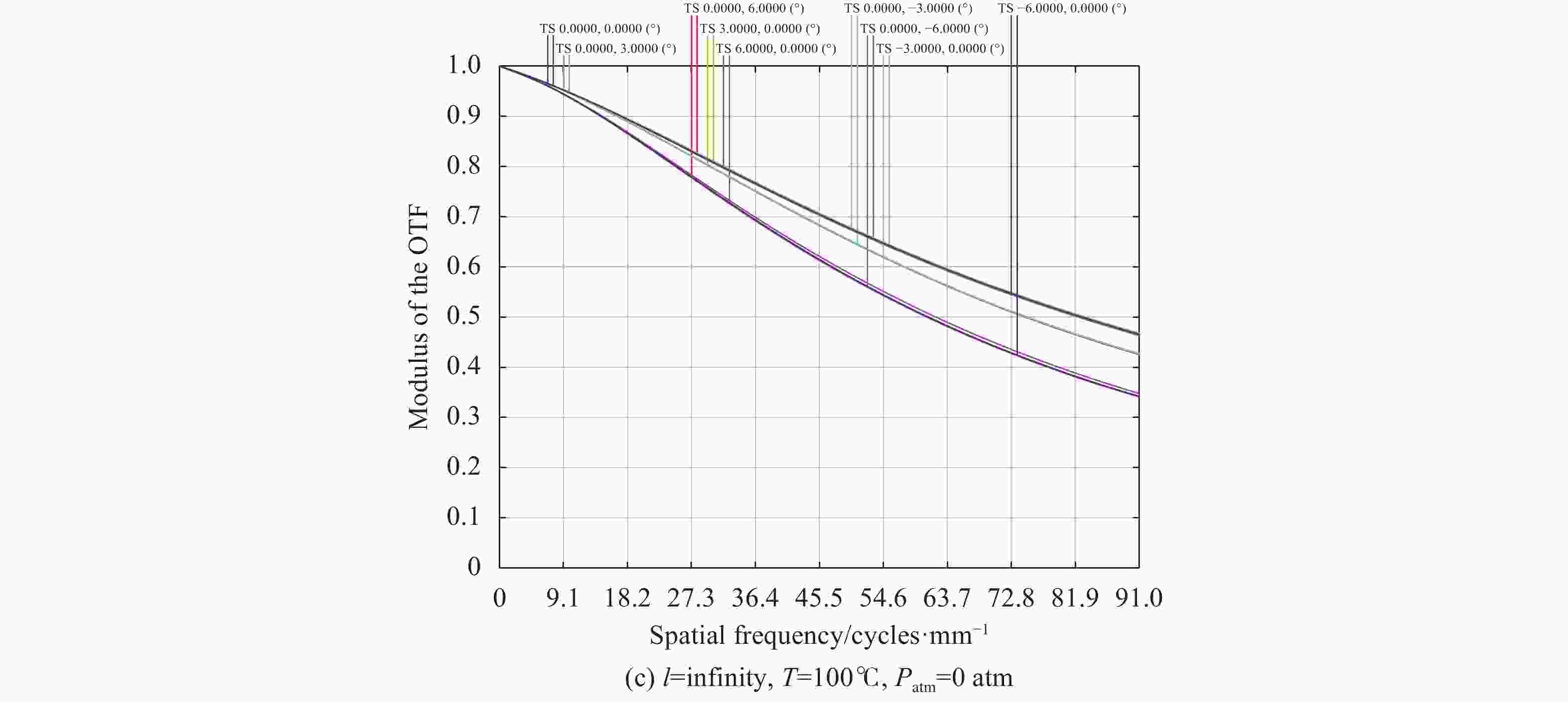
图 7 不同成像条件下的光学系统MTF曲线图
Figure 7. MTF diagram of optical system with different imaging conditions
-
文中基于自由曲面变焦的理论,设计了一种内调焦光学系统。光学系统的焦距为100 mm,波段范围为450~700 nm,相对口径为1/5.6,全视场为12°,系统总长为115 mm。物距调焦范围为无穷远到1.5 m,该光学系统通过自由曲面透镜组垂轴偏移的方法调整透镜组的光焦度,实现对入射光波复振幅的调制功能。物距调焦过程中,在奈奎斯特频率91 lp/mm处的全视场MTF大于0.3,具有宽物距的稳定成像性能,垂轴偏移量最大补偿量为0.1 mm。空间环境适应性分析中,在奈奎斯特频率91 lp/mm处的全视场MTF大于0.3,具有复杂空间环境的稳定成像能力,结合物距调焦范围,垂轴偏移量最大补偿量为0.1015 mm,微米级的补偿量适用于高精度的压电陶瓷驱动装置。
Design on internal focusing optical system with zoom lens of freeform
-
摘要: 具有调焦功能的光学系统在空间探测领域中有着重要的应用需求。设计了一种基于自由曲面垂轴偏移的内调焦光学系统,该系统中采用特殊自由曲面面型结构,构建自由曲面透镜组,利用垂轴偏移的变焦特性,改善光学系统的成像位置,提升在空间环境多样性和宽物距成像的适应性能力。具体分析了自由曲面透镜组的调焦原理,并成功将自由曲面透镜组应用到焦距为100 mm的光学系统中,分析像距扰动和物距变化两种情况下的成像质量和偏移量。结果表明,光学系统的调制传递函数在奈奎斯特频率处大于0.3,满足成像要求,该系统具有成像性能稳定和微米量级补偿量等特点。Abstract: Optical systems equipped with focusing ability are crucial for space exploration. The internal focusing optical system was designed which was based on the vertical deflection of the freeform surface. Specifically, the system used a special structure of the freeform surface to establish a lens group. It used the zoom ability of the vertical deflection to improve the imaging location thus adapting to different conditions such as wide range imaging or diverse space environments. The zoom theory of the freeform lens group was analyzed, and zoom lens of freeform was successfully applied to the optical system whose focal length was 100 mm. Then the imaging quality and displacements were analyzed when the object and image distance were changed accordingly. The results show that the Modulation Transfer Function (MTF) of the optical system is better than 0.3 at the Nyquist frequency which means satisfying quality of image. The system is stable in imaging and can provide compensation on the micron scale.
-
Key words:
- internal focusing system /
- zoom lens /
- freefrom /
- vertical deflection
-
图 5 不同物距时的垂轴偏移量
Figure 5. Displacement of vertical deflection with different object distance
图 7 不同成像条件下的光学系统MTF曲线图
Figure 7. MTF diagram of optical system with different imaging conditions
表 1 内调焦光学系统参数指标
Table 1. Specific parameters of internal focusing optical system
Parameter Value Focal length/mm 100 F number 5.6 Field of view/(°) 12 Wavelength/nm 450-700 Total length/mm 115 Size of pixel/μm2 5.5×5.5 Object length/m 1.5-Infinity Temperature/℃ −100~100 Atmosphere/atm 0-1  下载: 导出CSV
表 2 自由曲面透镜的参数特性
Table 2. Specific parameters of freeform lens
Title Type A9 Radius Thickness Materials Lens 1 Sphere - Infinity 1.5 H-ZPK7 XY polynomial 0.0009 Infinity 0.1 Lens 2 XY polynomial 0.0009 Infinity 3 H-ZPK7 XY polynomial −0.0009 Infinity 0.1 Lens 3 XY polynomial −0.0009 Infinity 1.5 H-ZPK7 Sphere - Infinity 2 Lens 4 Sphere - 32.74 5.30 H-ZK11 Sphere - 97.91 20.26 Lens 5 Sphere - 42.76 5.64 H-ZK11 Sphere - −36.33 0.64 Lens 6 Sphere - −33.70 4.50 H-ZF3 Sphere - 103.82 1.88 Lens 7 Sphere - −32.88 3.02 H-ZF3 Sphere - 24.68 1.59 Lens 8 Sphere - 25.87 8.91 H-ZK9B Sphere - 34.59 3.99 Lens 9 Sphere - 74.32 4.71 H-ZF12 Sphere - −44.04 46.37
下载: 导出CSV
-
[1] Wu Yanxiong, Qiao Jian, Wang Liping. Optical system design of star sensor with long focal length and athermalization [J]. Infrared and Laser Engineering, 2020, 49(9): 20200061. (in Chinese) doi: 10.3788/IRLA20200061 [2] Yu Tao, Xu Shuyan, Song Kefei. Auto-focusing system based on temperature for space camera [J]. Infrared and Laser Engineering, 2012, 41(8): 2085-2089. (in Chinese) doi: 10.3969/j.issn.1007-2276.2012.08.023 [3] Wang Kai, Yan Yong, Xu Minglin, et al. Design and experiment of precision focusing mechanism of space remote sensing camera with lightweight and miniaturization [J]. Infrared and Laser Engineering, 2018, 47(12): 1218004. (in Chinese) [4] Li Dan, Yang Bo, Shu Xinwei. The design for internal focusing telescope objective using binary optical lens [J]. Optical Instruments, 2015, 37(1): 31-34, 38. (in Chinese) doi: 10.3969/j.issn.1005-5630.2015.01.008 [5] Liu Zhiying, Li Shuqi, Huang Yunhan, et al. Design and analysis of the transmitted inner focusing wide spectrum optical system [J]. Acta Photonica Sinica, 2020, 49(3): 0322004. (in Chinese) [6] Zhu Jun, Wu Xiaofei, Hou Wei, et al. Application of freeform surfaces in designing off-axis reflective space optical imaging systems [J]. Spacecraft Recovery & Remote Sensing, 2016, 37(3): 1-8. (in Chinese) doi: 10.3969/j.issn.1009-8518.2016.03.001 [7] Yang Tong, Duan Yingzhe, Cheng Dewen, et al. Freeform imaging optical system design: Theories, development and applications [J]. Acta Optica Sinica, 2021, 41(1): 0108001. (in Chinese) [8] Tian Fei. Study on effect of machining errors on optical performance in freeform optics[D]. Tianjin: Tianjin University, 2016. (in Chinese) [9] Lee W, Cheung C, To Suet, et al. Ultra-precision machining technology of freeform optics and its applications [J]. Infrared and Laser Engineering, 2010, 39(1): 110-115. (in Chinese) doi: 10.3969/j.issn.1007-2276.2010.01.023 [10] Zou Y, Chau F, Zhou G. et al. Ultra-compact optical zoom endoscope using solid tunable lenses [J]. Optics Express, 2017, 25(17): 20675-20688. doi: 10.1364/OE.25.020675 [11] Petsch S, Grewe A, Köbele L, et al. Ultrathin Alvarez lens system actuated by artificial muscles [J]. Applied Optics, 2016, 55(10): 2718-2723. doi: 10.1364/AO.55.002718 -

 点击查看大图
计量
- 文章访问数: 508
- HTML全文浏览量: 169
- PDF下载量: 107
- 被引次数: 0


