


-
激光测距因其具有较好的准确度,较高的测距精度,测程远,抗干扰能力强等特点,在各个领域应用都比较广泛。光电探测器作为测距系统的核心部件之一,在测量过程中,需要对回波信号有很快的响应速度,同时又要保证较低的噪音[1-2]。现有的激光测距机系统探测器位置装调方法非常粗糙,是通过实验室内条件下,判断探测器接收到能量大小来确定的。由于光电二极管(APD)为积分型探测器,在实验室内环境下,无杂散光,延光轴一定范围内都接收到的能量都是一样的,无法进行精确标定[3-4]。但是在实际工作环境中,激光测距机在离焦量较大的位置时探测信噪比就很低,这时探测器的定位精度就显得非常重要了。随着对激光测距机性能指标的要求不断提升,迫切需要能够精确测量探测器离焦量的手段。目前对于光学系统离焦的测量方法有两类:一类是机械方法的接触式测量,这个对于已经进行集成为产品的激光测距机来说难以实现;另一类为采用光学手段的非接触式测量,例如傅科刀口法、临界角法和像散法等。但是这些方法都需要搭建复杂的测试光路,不适用于已经集成、封装为产品的激光测距机在线测量[5-8]。
为了解决上述问题,文中设计出了一种用主动光源照亮激光测距机探测器表面的测量系统,该系统能够通过裂像镜对探测器进行离焦检测。分析了裂像镜成像原理并建立了裂像离焦数学模型;对裂像方法的精度进行了探讨和仿真,从多个角度分析裂像方法应用中不同参数对测量精度的影响;设计完成了实验系统,对理论模型进行了误差校核,为此类研究提供了较好的科学和经验指导。
-
裂像镜是由两个折射率相同、顶角相等的斜面交叉的透明光楔组成。如图1所示,由于双光楔的作用,当光线的汇聚点在等厚线前或后时,物像被分成左右错开的上下两个部分,并且等厚线前和后的错开方向正好相反。汇聚点恰好在等厚线上时,像才会无错位连接,形成完整的物像[9-10]。
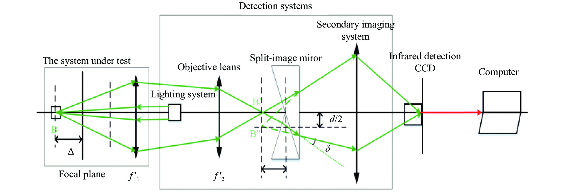
该研究利用这一原理所设计的离焦检测系统由五部分组成[11],分别是照明系统、物镜、裂像镜、二次成像系统、探测CCD以及计算机。
照明系统发出的光照亮被测探测器,被测探测器反射的光通过物镜进入裂像镜。如果被测探测器有一定的离焦量,那么裂像镜会把图像分开成上下两个有一定平移错位的像,如果被测探测器处于焦点位置,那么会得到一个完整的物像。二次成像系统把裂像镜所成的一次像准确成像到探测CCD上并被计算机捕捉,经过图像处理将给上下两个圆环横向位移的数值,通过此数值可以计算出被测探测器离焦量。
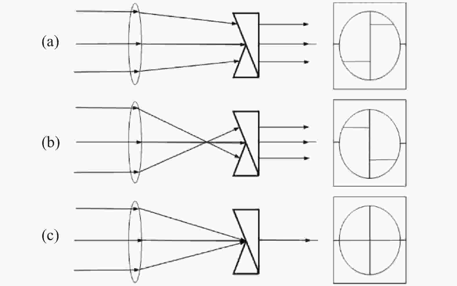
图 1 裂像镜成像示意图。(a)等厚线后;(b)等厚线前;(c)等厚线上
Figure 1. Schematic diagram of split-image mirror imaging. (a) After the equal thickness; (b) Before the equal thickness line; (c) Above the equal thickness
图2为离焦检测系统工作光路图,从物点B到焦平面有一探测器的微小离焦量
$\Delta $ ,相应地像点将移动$\Delta '$ ,即由裂像镜斜面交叉点到位置B′,折射光线的反向延长线交于点B′′。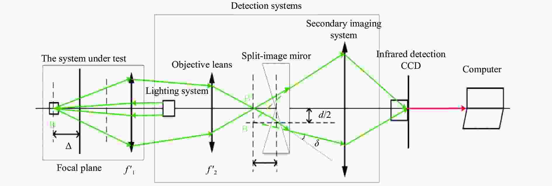
图 2 离焦检测系统光路图
Figure 2. Defocus detection system light path diagram
根据物方光学系统轴向放大率与垂轴放大率的关系[12]得:
$$ \frac{\Delta }{{{\Delta '}}} = {\left( {\frac{{f_1'}}{{f_2'}}} \right)^2} $$ (1) 式中:
$f_1'$ 为被测系统焦距;$f_2'$ 为检测系统焦距。根据棱镜偏向角公式,偏折角度δ与光楔的倾角α和光楔的折射率n有关。由于离焦量距离很小,光线近似于垂直射入光楔(入射角很小),出射角也很小,偏折角度满足
${\rm{\delta}} = \left( {{{n}} - 1} \right){{\alpha}}$ 。从图中的三角关系可以看出${\rm{\delta}} \approx d /2{\Delta '}$ 。整理两个公式可得两圆环横向位移量d:$$ \begin{split} \\ d = 2{\Delta '}\left( {{{n}} - 1} \right){{\alpha}} \end{split} $$ (2) 式中:α为裂像镜的顶角度数;n为裂像镜的折射率。
根据公式(1)、(2)还有二次成像系统垂轴放大倍率1得到裂像离焦公式:
$$ \Delta {\rm{ = }}\frac{{{{\left( {{{f'}_1}} \right)}^2}d}}{{2{{\left( {{{f'}_2}} \right)}^2}\left( {{{n}} - 1} \right){{\alpha }}}} $$ (3) 可见,激光测距机接收系统探测器离焦量的大小与被测系统焦距、检测系统焦距、裂像镜的折射率和顶角等因素有关。
-
由误差的独立性原理[13]和函数的随机误差公式可以得到离焦检测系统的检测精度:
$$ \sigma {\rm{ = }}\sqrt {\begin{array}{l} {\left[ {\dfrac{{f_1'd}}{{{{\left( {f_2'} \right)}^2}\left( {{{n}} - 1} \right){{\alpha }}}}} \right]^2}{\partial ^2}f_1' + {\left[ {\dfrac{{ - {{\left( {f_1'} \right)}^2}{{d}}}}{{{{\left( {f_2'} \right)}^3}\left( {{{n}} - 1} \right){\rm{\alpha }}}}} \right]^2}{\partial ^2}f_2'{\rm{ + }}{\left[ {\dfrac{{{{\left( {f_1'} \right)}^2}}}{{2{{\left( {f_2'} \right)}^2}\left( {{{n}} - 1} \right){{\alpha }}}}} \right]^2}{\partial ^2}d{\left[ {\dfrac{{ - {{\left( {f_1'} \right)}^2}d}}{{2{{\left( {f_2'} \right)}^2}{{\left( {{{n}} - 1} \right)}^2}{{\alpha }}}}} \right]^2}{\partial ^2}{{n}} + {\left[ {\dfrac{{ - {{\left( {f_1'} \right)}^2}d}}{{2{{\left( {f_2'} \right)}^2}\left( {{{n}} - 1} \right){{{\alpha }}^2}}}} \right]^2}{\partial ^2}{{\alpha }} \end{array}} $$ (4) 在该离焦检测方法中使用的是间接测量[14-15],通过对两圆环横向位移量的测量推导出被测系统接收端探测器离焦量的大小。根据离焦检测系统精度公式(4),可以分析出影响离焦量测量精度的因素有五个误差源: (1)被测系统的焦距误差
$\partial f_1'$ ,焦距仪的测量误差一般为0.5%,被测系统焦距误差$\partial f_1'{\rm{ = }}0.5 {\text{%}} f_1'$ ;(2)检测系统的焦距误差$\partial f_2'$ ,物镜的焦距误差$\partial f_2'{\rm{ = }} $ $ 0.5 {\text{%}} f_2'$ ;(3)两圆环横向位移量误差$\partial d$ ,选用的探测CCD的像素尺寸为20 μm,为了提高CCD的分辨率,将CCD像素尺寸进行了十细分,$\partial d = {\rm{0}}{\rm{.002\;mm}}$ ;(4)裂像镜折射率误差$\partial {{n}}$ ,查阅成都光明玻璃相关资料[16]得到H-K9L玻璃的折射率误差,符合GB/T 903折射率标准值偏差$\partial {{n}}{\rm{ = }}10 \times {10^{{\rm{ - }}5}}$ ;(5)裂像镜顶角误差$\partial {{\alpha}}$ ,查阅相关论文[17]得到光楔顶角加工误差$\partial {{\alpha}} {\rm{ = }}10''$ 。根据公式(4),提取公因式整理得:
$$\sigma {\rm{ = }}\sqrt {{{\left[ {\dfrac{{f_1'd}}{{{{\left( {f_2'} \right)}^2}\left( {{{n}} - 1} \right){{\alpha }}}}} \right]}^2}\left[ {{\partial ^2}f_1'{\rm{ + }}{{\left( {\dfrac{{f_1'}}{{f_2'}}} \right)}^2}{\partial ^2}f_2'{\rm{ + }}\dfrac{{{{\left( {f_1'} \right)}^2}}}{{4{d^2}}}{\partial ^2}d{\rm{ + }}\dfrac{{{{\left( {f_1'} \right)}^2}}}{{4{{\left( {{{n}} - 1} \right)}^2}}}{\partial ^2}{{n + }}\dfrac{{{{\left( {f_1'} \right)}^2}}}{{4{{{\alpha }}^2}}}{\partial ^2}{{\alpha }}} \right]} $$ (5) 由公式(5)可知,裂像对焦屏顶角α处于公因式分母位置且为平方项,裂像对焦屏顶角α越大,系统总误差越小;检测系统焦距误差
$\partial f_2'$ 的系数为${\left( {f_1'/f_2'} \right)^2}$ ,为了提高检测精度,选取的检测系统焦距比被测系统焦距大,并且此系数为平方项,由此可见检测系统焦距误差$\partial f_2'$ 对离焦检测精度的影响不大;两圆环横向位移量误差$\partial d$ 的系数为$[{\left( {f_1'} \right)^2}/4{d ^2}]$ ,裂像镜折射率误差$\partial {{n}}$ 的系数为$[{\left( {f_1'} \right)^2}/4{\left( {{{n}} - 1} \right)^2}]$ ,裂像镜顶角误差$\partial {\rm{\alpha}} $ 的系数为$[{\left( {f_1'} \right)^2}/4{{{\alpha}} ^2}]$ ,由于$f_1'$ 远远大于d值、(n−1)值、${{\alpha}}$ 值大,并且其系数为平方项,由此可见两圆环横向位移量误差$\partial d$ 、裂像镜折射率误差$\partial {{n}}$ 、裂像镜顶角误差$\partial {{\alpha}}$ 对离焦检测精度的影响比较大。由于被测系统焦距误差$\partial f_1'$ 和物镜焦距误差$\partial f_2'$ 本身数量级大,综合分析,它们对离焦检测精度影响较大。根据被测激光测距机参数,
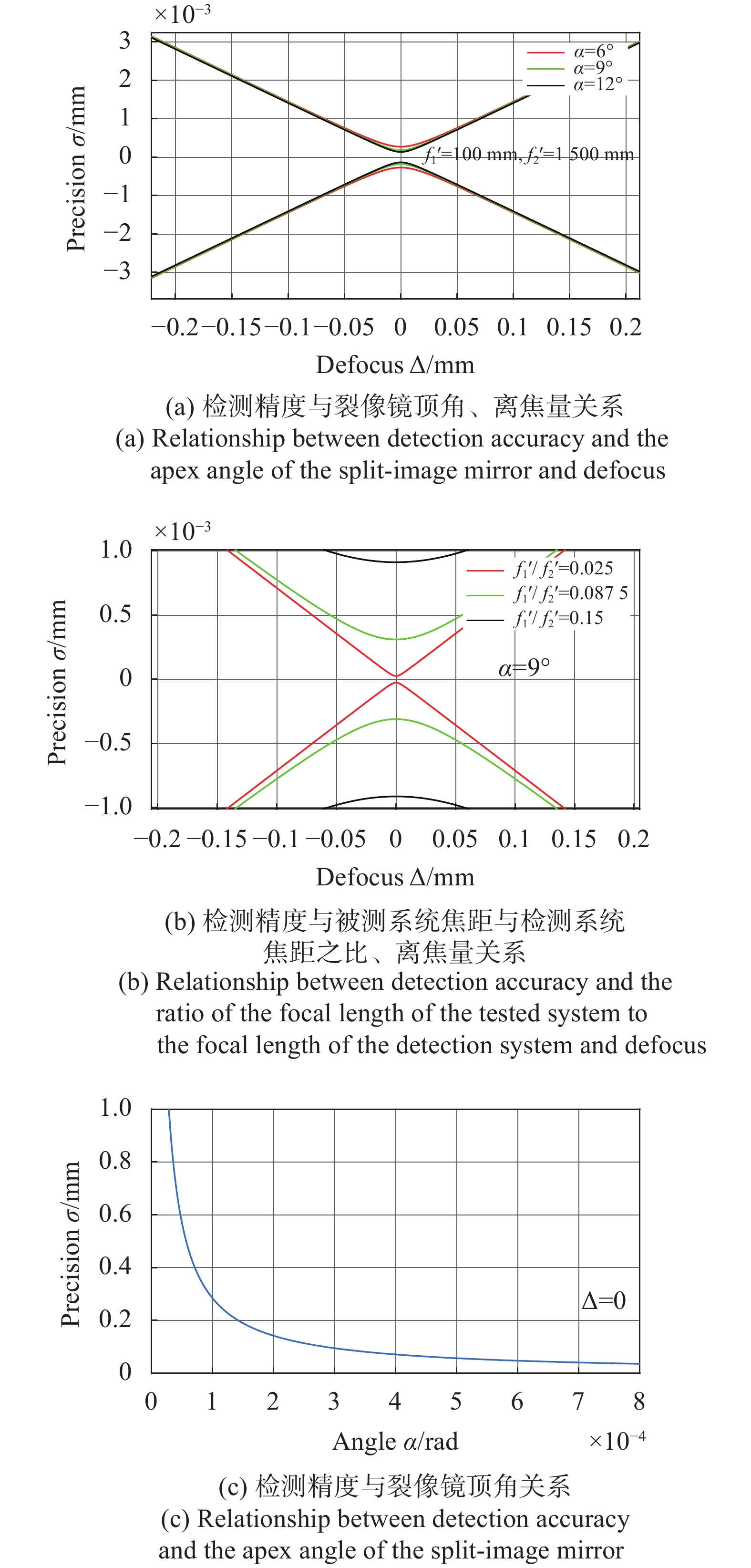
$f_1'$ 取50~150 mm。为了提高该离焦检测系统精度,$f_2'$ 取1 000~2 000 mm。裂像镜的顶角α数值过大时会出现通过裂像镜的光线急剧减弱,使其呈现被遮黑状态而无法检测离焦,为了兼顾测焦精度与测焦能力,α取6°~12°。由以上分析可得到离焦检测精度与裂像镜顶角α、被测系统焦距与检测系统焦距之比$(f_1'/f_2')$ 的关系如图3所示。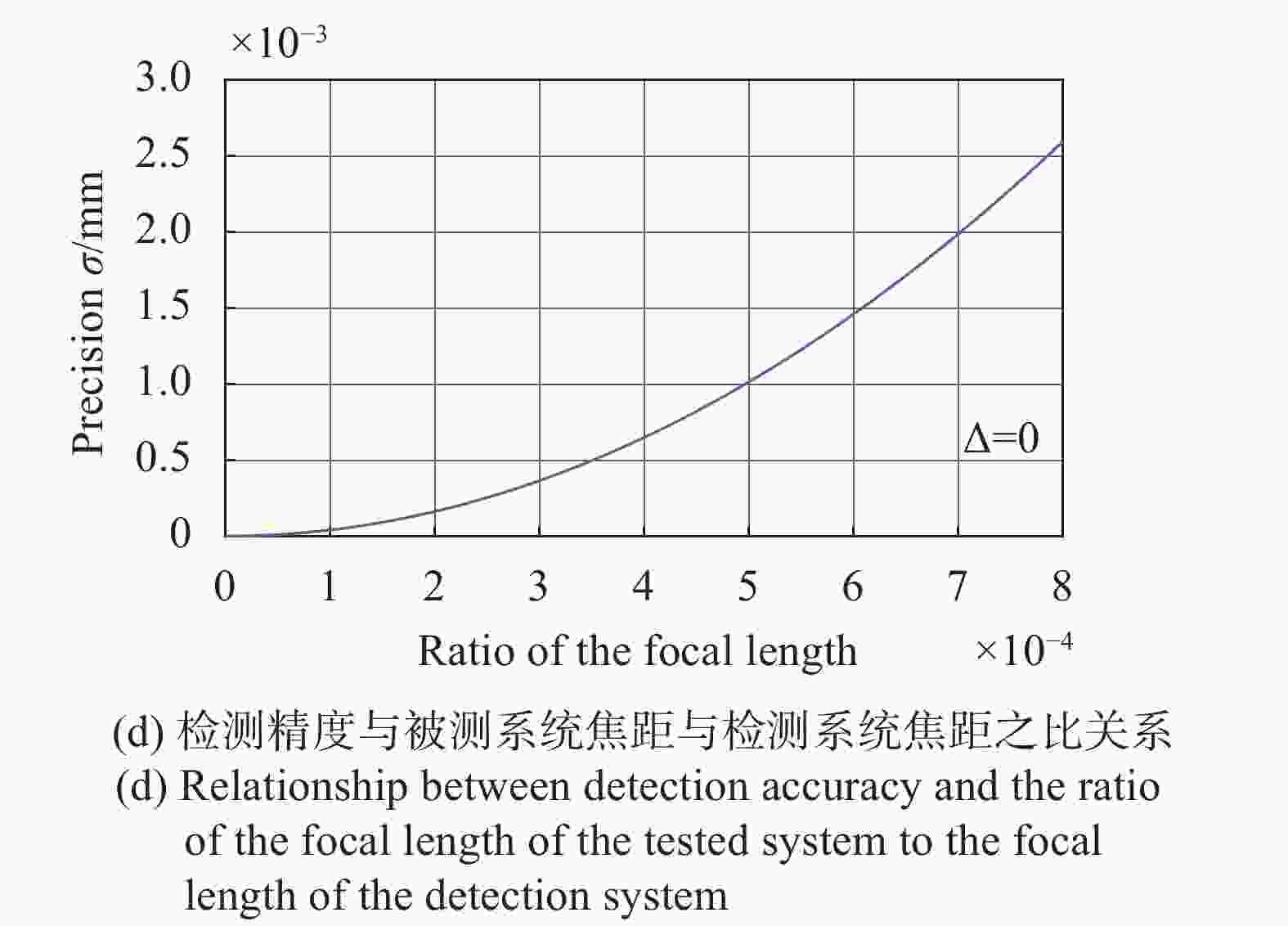
图 3 离焦检测精度与裂像镜顶角、被测系统焦距与检测系统焦距之比的关系示意图
Figure 3. Schematic diagram of the relationship between the defocus detection accuracy and the apex angle of the split-image mirror, the ratio of the focal length of the tested system to the focal length of the detection system
由图3(a)可以看出,在其他变量一定且测量相同大小离焦量的时候,裂像镜的顶角α越大,离焦检测精度
$\sigma$ 就越高,在离焦量$\Delta $ 越小的时候,不同顶角所对应的精度$\sigma$ 差别越大,此时离焦量$\Delta $ 与检测精度$\sigma$ 关系为双曲线关系;由图3(c)得到在离焦量$\Delta {\rm{ = }}0$ 时,离焦检测精度$\sigma$ 是顶角α的反比例函数,顶角α越大,检测精度$\sigma$ 越高且无限趋近于0;由图3(d) 得到在离焦量$\Delta {\rm{ = }}0$ 时,离焦检测精度$\sigma$ 是被测系统焦距与物镜焦距的比值$(f_1'/f_2')$ 呈现二次函数关系,焦距比值$(f_1'/f_2')$ 越大,检测精度$\sigma$ 越低;由图3(b)可以看出在$\Delta {\rm{ = }}0$ 离焦量$\Delta {\rm{ = }}0$ 的时候,离焦检测精度$\sigma \ne 0$ ,有一定的系统误差;在离焦量$\Delta $ 越来越小的时候,函数图像越来越陡,斜率越来越大,离焦检测精度$\sigma$ 越来越高,符合测量习惯。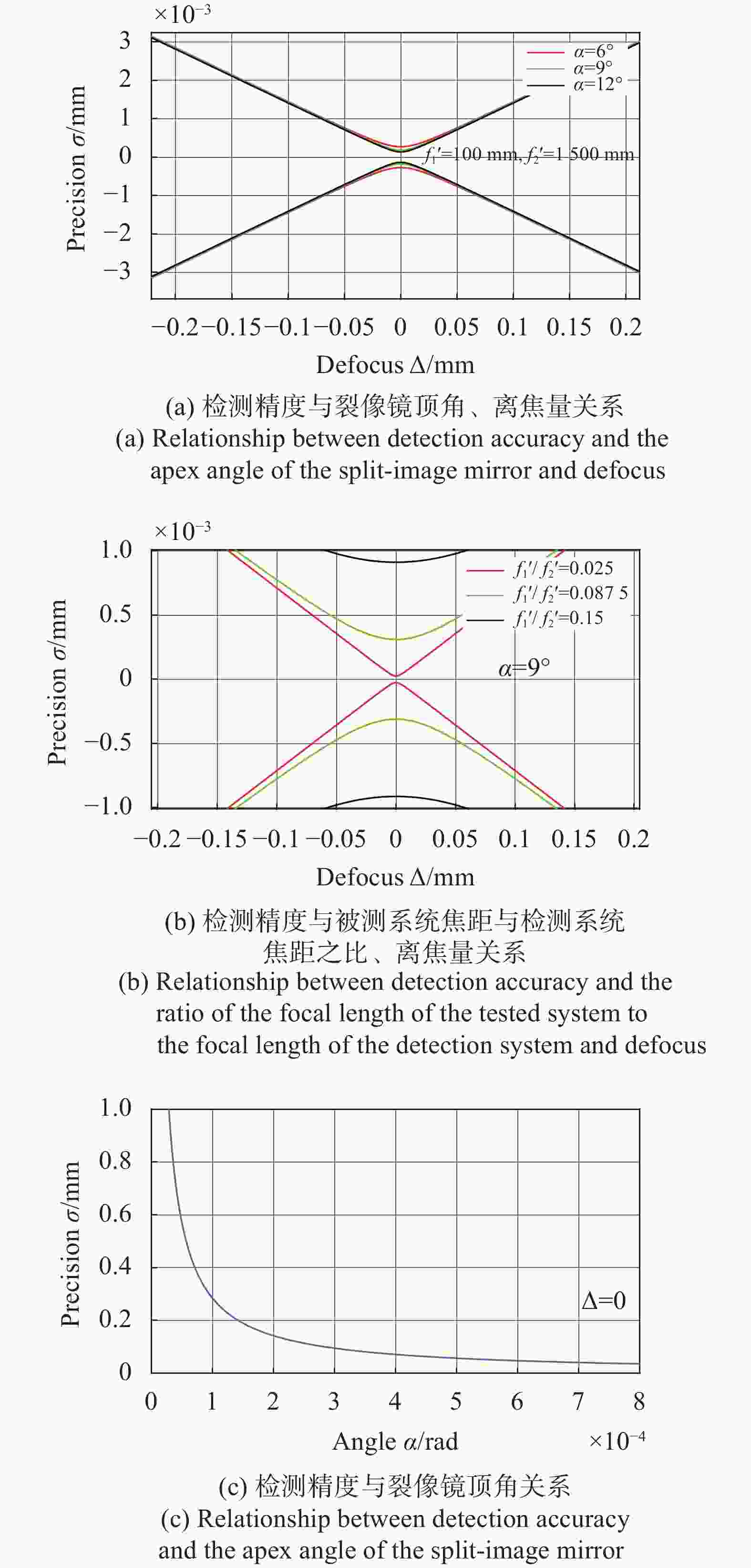
-
依据上述检测方法,设计了离焦检测系统,并在实验室的气浮平台上搭建了一套装置对此离焦检测系统进行检测,如图4所示。

图 4 系统检测图。(a)装置图; (b)示意图
Figure 4. System inspection diagram. (a) Installation drawing; (b) Sketch map
笔者研究所设计的离焦检测系统的物镜焦距为1 500 mm,裂像镜倾角为12°。取一焦距为100 mm的光学系统和一探测器模拟被测激光测距机接收系统。物镜焦距和被测系统焦距由焦距仪测量,焦距仪的测量误差一般为0.5%,裂像镜倾角加工误差为
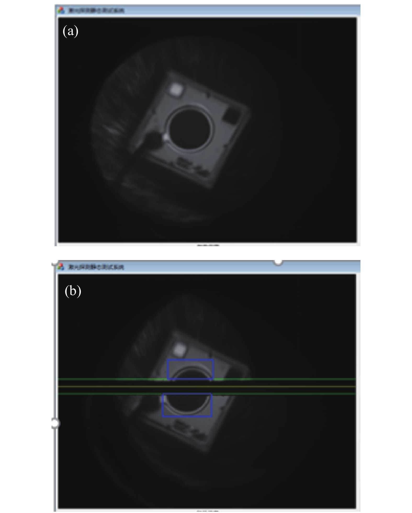
$\partial {{\alpha}} {\rm{ = }}10''$ 。进行系统检测时,把被测探测器放置在此光学系统焦点附近。打开激光器,激光器发出的光束经过半反半透波片,100 mm焦距光学系统,照亮被测探测器。被测探测器反射的光沿原光路返回,经过离焦检测系统,汇聚到CCD上并被捕捉,计算机能显示出离焦信息,如图5所示。给被测探测器一个确定的位移量,同时测量并记录其离焦量的大小。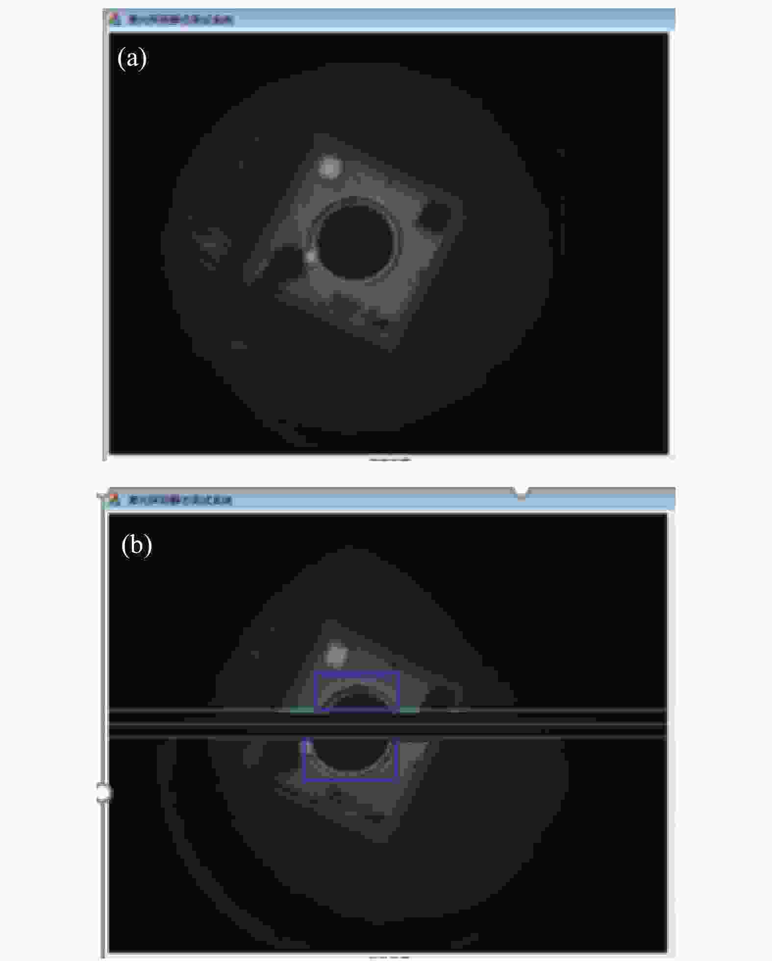
图 5 计算机显示的离焦信息。(a)未离焦状态;(b)离焦状态
Figure 5. Defocus information displayed by computer. (a) Unfocused state; (b) Defocus state
表1给出三组实验测量数据(I、II、III、Ⅳ、Ⅴ、Ⅵ),ACT表示实际离焦量,MEA表示测量离焦量,1、2、3、4、5分别为5次的实际测量的离焦量值。
表 1 测量数据
Table 1. Measurement data
ACT/mm MEA MEA average/mm 1 2 3 4 5 I 1 0.986 1.005 0.985 0.995 1.012 0.997 II 2 1.971 2.022 2.024 1.973 1.992 1.996 III 3 2.957 3.024 3.002 3.041 2.987 3.006 Ⅳ 4 4.051 4.033 3.947 4.046 3.965 4.008 Ⅴ 5 5.066 4.929 5.063 5.020 4.981 5.012 Ⅵ 6 5.920 6.080 5.995 6.051 6.025 6.014 从表2的三组数据分析结果可以看出,标准差、最大误差、极限误差,随着离焦量的增加而增大。离焦量为0~6 mm的时候,检测精度可以达到0.07 mm。
表 2 实验分析结果
Table 2. Experimental analysis results
Standard deviation/mm Maximum error/mm Limit error/mm I 1.181×10⁻² 0.015 1.373×10⁻² II 2.564×10⁻² 0.029 2.982×10⁻² III 3.289×10⁻² 0.043 3.824×10⁻² Ⅳ 4.870×10⁻² 0.051 5.663×10⁻² Ⅴ 5.795×10⁻² 0.071 6.738×10⁻² Ⅵ 6.132×10⁻² 0.080 7.131×10⁻² 根据表1和表2的数据绘制得到离焦量测量值平均值拟合曲线、理论误差曲线和极限误差曲线,如图6所示。

图 6 离焦量测量比较曲线
Figure 6. Comparison curve of defocus measurement
从图中可以看出,离焦量测量值平均值拟合曲线线性度近似为1;把理论误差曲线与极限误差曲线进行对比,可以明显看出理论误差曲线基本高于极限误差曲线,误差较为接近理想值,说明此离焦检测系统能够实现激光测距系统接收系统探测器离焦量的高精度测量。
-
文中针对激光测距机接收端探测器离焦量的测量,设计了一种基于裂像镜的离焦检测设备。介绍了其工作原理,并对其检测精度进行了理论分析。针对影响检测结果的被测系统焦距与物镜焦距的比值以及裂像镜顶角,给出了在选择他们的各自不同参数时,对检测精度影响的变化趋势。通过对各项参数的深入精度分析,得知被测系统焦距和物镜焦距对离焦检测精度影响比较大,且被测系统焦距越大,离焦检测精度越低;物镜焦距越大,离焦检测精度越高;离焦量越大,离焦检测精度越低。
使用焦距一定的光学系统代替被测激光测距系统探测器对此理论样机进行了测试,实验结果表明:在离焦量为0~7 mm时,检测精度可以达到0.07 mm,较为接近理想值,验证了此离焦检测系统高精度装调的可行性及装调规律。
Application of split-image mirror in defocus detection of laser rangefinder
-
摘要: 为了减小探测器离焦问题对激光测距系统的影响,设计了一种基于裂像镜的主动型测距机探测器装调系统。首先,分析了裂像镜的成像原理,并对其检测精度进行了理论分析,构建了裂像离焦数学模型;其次,针对影响检测的误差因素,给出了不同取值下的误差曲线,得到了检测精度影响的变化趋势;最后,设计完成理论样机并进行实验验证。实验结果表明:理论样机在离焦量为0~6 mm时,检测精度可以达到0.07 mm, 较为接近理想值,且离焦量越小离焦检测精度越高,符合装调测量习惯。该离焦检测系统为非成像型光电探测器装调提供了一种新方法,能够进一步提高激光测距系统的测量精度。Abstract: In order to reduce the impact of the detector out-of-focus problem on the laser rangefinder system, an active rangefinder detector adjustment system based on split-image mirror was designed. Firstly, the imaging principle of the split-image mirror was analyzed, and its the detection accuracy was theoretically analyzed, and a mathematical model of split-image defocus was established; Secondly, in view of the error factors that affected the detection, the error curve under different values was given, and the change trend of the detection accuracy was obtained; Finally, the theoretical prototype was designed and verified by experiments. The experimental results show that when the defocus is 0-6 mm, the detection accuracy can reach 0.07 mm, close to the ideal value, and the smaller the defocus, the higher the defocus detection accuracy, which is in line with the installation and measurement habits. The defocus detection system provides a new method for the adjustment of non imaging photoelectric detector, which can further improve the measurement accuracy of laser rangefinder system.
-
Key words:
- defocus detection /
- split-image mirror /
- precision analysis /
- laser rangefinder
-
图 1 裂像镜成像示意图。(a)等厚线后;(b)等厚线前;(c)等厚线上
Figure 1. Schematic diagram of split-image mirror imaging. (a) After the equal thickness; (b) Before the equal thickness line; (c) Above the equal thickness
图 3 离焦检测精度与裂像镜顶角、被测系统焦距与检测系统焦距之比的关系示意图
Figure 3. Schematic diagram of the relationship between the defocus detection accuracy and the apex angle of the split-image mirror, the ratio of the focal length of the tested system to the focal length of the detection system
图 4 系统检测图。(a)装置图; (b)示意图
Figure 4. System inspection diagram. (a) Installation drawing; (b) Sketch map
图 5 计算机显示的离焦信息。(a)未离焦状态;(b)离焦状态
Figure 5. Defocus information displayed by computer. (a) Unfocused state; (b) Defocus state
表 1 测量数据
Table 1. Measurement data
ACT/mm MEA MEA average/mm 1 2 3 4 5 I 1 0.986 1.005 0.985 0.995 1.012 0.997 II 2 1.971 2.022 2.024 1.973 1.992 1.996 III 3 2.957 3.024 3.002 3.041 2.987 3.006 Ⅳ 4 4.051 4.033 3.947 4.046 3.965 4.008 Ⅴ 5 5.066 4.929 5.063 5.020 4.981 5.012 Ⅵ 6 5.920 6.080 5.995 6.051 6.025 6.014  下载: 导出CSV
表 2 实验分析结果
Table 2. Experimental analysis results
Standard deviation/mm Maximum error/mm Limit error/mm I 1.181×10⁻² 0.015 1.373×10⁻² II 2.564×10⁻² 0.029 2.982×10⁻² III 3.289×10⁻² 0.043 3.824×10⁻² Ⅳ 4.870×10⁻² 0.051 5.663×10⁻² Ⅴ 5.795×10⁻² 0.071 6.738×10⁻² Ⅵ 6.132×10⁻² 0.080 7.131×10⁻²
下载: 导出CSV
-
[1] Gu Xiaokun, Li Yongliang, Hu Weiwei, et al. Research progress of dector unit in laser ranging system [J]. Journal of Quantum Optics, 2019, 25(1): 106-114. (in Chinese) [2] Liu Hexiong, Zhou Bing, Gao Yuchen. Research of noise characteristics and influence factors of APD detection systems [J]. Laser Technology, 2018, 042(6): 862-867. (in Chinese) [3] Liu Bo, Chen Nianjiang, Zhang Zhongping, et al. Micro pulse laser ranging technology for human satellite [J]. Infrared and Laser Engineering, 2008, 37(S3): 234-237. (in Chinese) [4] 许翔. 多功能激光测距系统研究[D]. 长沙: 国防科学技术大学, 2006. Xu Xiang. The study of multifunctional laser ranging finder system[D]. Changsha: National University of Defense Technology, 2006. (in Chinese) [5] 胡毅斐. 可用于工件内腔尺寸测量的共焦式激光测量方法研究[D]. 西安: 西安理工大学, 2019. Hu Yifei. Research of confocal laser measurement method for dimensional measurement of workpiece cavity[D]. Xi'an: Xi'an University of Science and Technology, 2019. (in Chinese) [6] Luo Qijun, Ge Baozhen. An automatic focusing method of a telescope objective lens based on the defocusing estimation of a circular edge response [J]. Chinese Optics, 2020, 13(4): 760-769. (in Chinese) doi: 10.37188/CO.2019-0247 [7] Jiang Tingjia, Jiang Man, Ruan Bin, et al. Effect of the center deviation of focusing spot on the measurement precision in the astigmatic defocus detecting system [J]. Optical Technology, 2013, 39(6): 483-487. (in Chinese) [8] Hao Xianpeng, Ren Jianyue, Zou Zhenshu. Design of focus error detection system based on critical angle method [J]. Optics and Precision Engineering, 2009, 17(3): 537-541. (in Chinese) doi: 10.3321/j.issn:1004-924X.2009.03.012 [9] Zhang Yunhai, Zhao Gaina, Zhang Zhonghua, et al. Accurate focusing of non-mydriatic fundus camera [J]. Optics and Precision Engineering, 2009, 17(5): 1014-1019. (in Chinese) doi: 10.3321/j.issn:1004-924X.2009.05.038 [10] Liu Xingyun, Hu Dejin. Simulative experimental instrument based on central split-image focusing [J]. Physics Experimentation, 2003(1): 29-31. (in Chinese) doi: 10.3969/j.issn.1005-4642.2003.01.007 [11] Zhong Hui. Focal plane alignment for remote sensing camera with dual focal plane of large field of view interval [J]. Infrared and Laser Engineering, 2021, 50(2): 20200172. (in Chinese) [12] 郁道银, 谈恒英. 工程光学[M]. 北京: 机械工业出版社, 2011. Yu Daoyin, Tan Hengying. Engineering Optics[M]. Beijing: China Machine Press, 2011. (in Chinese) [13] 马宏, 王金波. 仪器精度理论[M]. 北京: 北京航空航天大学出版社, 2014. Ma Hong, Wang Jinbo. Theory of Instrument Accuracy[M]. Beijing: Beijing University Press, 2014. (in Chinese) [14] Zhao Yuping, Peng Chuanqian, Wang Jie, et al. Analysis of error source for large aperture thin beam auto-collimating measurement system [J]. Semiconductor Optoelectronics, 2018, 39(3): 414-419. (in Chinese) [15] Cheng Zhiji, Huang Qiangxian, Ying Qiancheng, et al. Analysis and correction of defocus error of auto-collimation measurement system [J]. China Measurment, 2020, 46(5): 7-12. (in Chinese) [16] 成都光明光电股份有限公司. 成都光明光学玻璃数据库[Z]. 2019. Chengdu Guangming Optoelectronics Co., Ltd. Chengdu Guangming Optical Glass Library Data[Z]. Chengdu: Chengdu Guangming Optoelectronics Co., Ltd., 2019. [17] Lv Bo, Han Guohua. Application of dual wedges in optical axis alignment for laser rangefinders [J]. Laser Technology, 2012, 36(2): 151-153,159. (in Chinese) doi: 10.3969/j.issn.1001-3806.2012.02.014 -

 点击查看大图

计量
- 文章访问数: 314
- HTML全文浏览量: 149
- PDF下载量: 33
- 被引次数: 0


