


-
In recent years, large field of view (FOV) angle optical imaging system, such as fish-eye lens and catadioptric panoramic imaging system, have attracted more and more attention. It has been widely used in robot or vehicle navigation, positioning, scene monitoring, external space detection, micro intelligent system and so on. In daily life, the fish-eye lenses are also used by many photography enthusiasts. In April 2015, Ricoh released a 360° panoramic camera, which used two fish-eye lens systems with a field of view angle more than 180° to realize the imaging of the three-dimensional angle of the whole space, causing people’s attention all over the world.
The field of view angle of fish-eye lens system reach or even exceed 180°. The beam focus, wave array surface and aberration of the optical system in the meridian and sagittal plane are totally different, which has the imaging characteristics of the plane symmetric optical system. At the same time, people often pursue the large aperture imaging (e.g. F#<3). Therefore, this kind of system has three characteristics: plane symmetry, super large field of view, and large aperture imaging, which make the design of fish-eye lens optical system very complex. Aberration theory is an important means to study optical system. Because of the plane symmetry imaging characteristics for this kind of lens system. Seidel primary aberration and high-order aberration theories that develop from axisymmetric optical system are no longer suitable for aberration analysis and design of this super large field of view optical system.
The conventional lens design of different structures and their aberration characteristics are quite clear[1]. From the book, fish-eye lens optics written by Wang Yongzhong[2], it is also pointed out that there is no a law in the structure and parameter design for fish-eye lens system. Most people use patents as the initial structure, and then use some commercial software to improve and optimize the initial structure repeatedly. Due to the lack of the aberration theory guidance, the selection of the initial structure of the fish-eye lens optical system is blind. We do not know what kind of aberration characteristics it has, and whether the initial structure is reasonable enough to determine the final performance of the fish-eye lens. Secondly, the commercial software application to optimize system parameters depends on algorithm to a great extent, and its design process is essentially "black box operation". If we can use reasonably the precise wave aberration theory for the optical system with super large field of view, we can analyze the function and contribution and all kinds of aberration of the different optics lens in the fish-eye lens system, we can analysis how to design the optical system structure and parameters and achieve the ideal aberration balance.
For the optical system of large aperture imaging, the effect of higher-order aberrations becomes significant[3]. The aberration accuracy using fourth-order wave aberration theory is not enough. We use the modulation transfer function based on the fourth-order wave aberration theory as the evaluation function to optimize the design of Nikon 16 mm/F2.8 fish-eye lens. We take the original design of the optical lens parameters as the initial value, and search in a large range for its optimization. The results show that the performance of the optimization results is better than the original design in the case of small aperture (F#<5), but worse in the case of large aperture. Therefore, only further development of the higher-order aberrations optical system theory with super large field of view, can we objectively research the imaging law of such fish-eye lens system.
It is a classical method to solve optical system aberration with wave aberration theory, and it is more suitable for the aberration analysis and calculation of multi-element optical system. For a multi-element optical system, the total system wave aberration is the sum of the wave aberrations for each elements. However, the derivation model of the wave aberration expression with a single element generally assume that the object point is an ideal geometric object point. According to the first-order optical surface parameters, the correlation ray path is expanded into a series of pupil coordinates and field angle, and then every order wave aberration expression (called intrinsic wave aberrations) is obtained. Except for the first optical plane, the other optical plane in a multi-element optical system, due to the aberration influence by its front optical system, the assumption of the ideal geometry point is not tenable in a strict sense. Therefore, the intrinsic wave aberration only reflect the single system element aberration in a real sense. The intrinsic wave aberration ahead of system will produce a correction amount of wave aberration (called derivative wave aberration), which is related to the intrinsic wave aberration of the optical plane and the optical system ahead of it. Therefore, the aberration with multi-element optical system is composed of the intrinsic aberration and the derivative aberration. For large aperture imaging optical system, the contribution of derivative aberration cannot be ignored. The evolution process of higher-order intrinsic aberration is basically the same as that of lower-order intrinsic aberration, but the evolution ideas of derivative aberrations and intrinsic aberrations are totally different. The research on derivative aberrations for the plane symmetric optical system cannot directly apply the derivative aberrations methods by axisymmetric optical system. Secondly, for the paraxial optical system aberration, the light pupil coordinates transmission on the adjacent optical surface is generally treated as in a linear way, the nonlinear term contribution is generally small and its influence on the aberration can be ignored. However, for a large field of view optical system, such as a fish-eye lens, the light beams from object with large field of view hit the optical surface. If the pupil coordinates transmission between adjacent optical surfaces is still treated as a linear way, there will be more calculation error with the increase of aperture. Through the research on many fish-eye lens systems, it is shown that the nonlinear term in the pupil coordinate transfer relationship has a significant effect on the object point wave aberration in a large field of view optical system, even more than the derivative wave aberration.
The basic structure of the fish-eye lens is composed of the former group with several large negative meniscus optical power lenses and the latter group with several common objective lenses. The former group is mainly used to compress the field angle. Most of the aberration analysis involved in the fish-eye lens research reports is still based on Seidel’s primary aberration theory. Dai Jianning, in his doctoral dissertation on fish-eye lens research[4], the aberration of several field rays and aperture rays is calculated by ray tracing to measure the high-order spherical aberration and high-order coma approximately, and it is included in the evaluation index of optimization design. The aberration theory can play an important guiding role in the initial structure and parameter design for the fish-eye lens optical system[5].
In some professional optical design software, the sampling optical light path difference is mostly used to simulate the wave aberration distribution at the exit pupil of optical system, and then calculate the optical system transfer function to evaluate its imaging and its accuracy, that all depend on the number of sampling light. The evaluation function based on the wave aberration theory includes only one or several aberrations contribution. In addition, it is different from the calculation method of light sampling.
-
The sixth-order wave aberration theory mainly include the sixth-order intrinsic wave aberration, the fifth order aberration, and the derivative wave aberration and the influence of the second order precision of pupil coordinates on the wave aberration of plane symmetric optical system.
-
According to the fourth-order wave aberration theory of plane symmetric optical system developed by Lu Lijun, the sixth-order accuracy expressions of meridian and sagittal focal line with respect to pupil coordinates are obtained by using the torus as the reference wave surface[6]. Then, by using ray equation and polynomial fitting method, the mapping relationship between the light coordinates of the incident/outgoing wave array and the optical element surface is obtained. According to the wave aberration definition of the plane symmetric optical system, the intrinsic wave aberration coefficients from the first-order to the sixth-order can be obtained by expanding the optical path of the relevant ray path with respect to the pupil coordinates according to the sixth-order number. The aberration coefficients from the first-order to the fourth-order are the same as those in the original fourth-order aberration theory[6]. The fifth-order and the sixth order aberration coefficients are w140, w320, w500, w600, w420, w240 and w060 respectively.
The wave aberration calculation is based on the first-order optical system parameters. The parameters of the main light ray in the optical path are calculated using the main light ray transfer equation. Based on the first-order and the second-order wave aberration coefficients (monochromatic aberration is calculated for D light), the object and the image distance of each optical plane in the meridian and sagittal plane are determined. These basic optical path parameters can be used to calculate the each order wave aberration coefficients of the optical system[7].
-
The solution of the fifth-order aberration is the same as the original fourth-order wave aberration theory, but the correlation expression is required to keep the sixth-order accuracy. The first-order to the third-order aberration coefficients are consistent with the original fourth-order wave aberration theory. The fourth-order and fifth-order meridional and sagittal aberration coefficients are d400, d220, d040, d500, d320, d140, h310, h130, h410, h230, h050 respectively.
-
As shown in Fig.1, it shows the relevant coordinate systems used in the main ray transmission and aberration calculation. In the process of calculation, all the relevant coordinate systems adopt the right hand rule, and the positive direction of y-axis is from the inside to the outside, x1O1z1 and x2O2z2 are the optical surface coordinate systems of M1 and M2 respectively. P0P1P2 is any aperture ray, and A1O1O2 is the main ray.
$ {\alpha }_{1} $ ,$ \;{\beta }_{1} $ ,$ {\alpha }_{2} $ and$ \;{\beta }_{2} $ are the incident angle and refraction angle of the optical plane M1 and M2 respectively, which are determined by the main ray transfer equation. But in the correlation processing of other aberrations, the incident angle of each optical plane should be increased by 180°, because the incident or refraction angle of the ray is defined by reference to the z axis. In the calculation of wave aberration and other relevant aberration, the ray coordinates on the final optical plane are set as the pupil reference coordinates.
Figure 1. Optical scheme of an aperture ray P0P1P2 passing through a double-element optical system
-
Figure 2 shows two element systems consisting of M1 and M2 optical surfaces. P1P2B is any aperture ray, A1O1O2 is the main ray, x′01O1y′01 is the outgoing wave array coordinate system of M1, x02O2y02 and x′02O2y′02 are the incoming and outgoing wave array coordinate systems of M2, and
$ \overline {{d}_{1}} $ is the distance between M1 and M2 along the main light ray.
Figure 2. Coordinate systems of the wave surface and the image plane in the reverse optical path of a double-element optical system
The coordinate (x2, y2) of the light on M2 are the pupil reference optical coordinate system. The reverse optical path is used to calculate the wave aberration of optical surface M2 on M1, and to correct the pupil coordinates of M1. In Fig.2,
$ {x}_{2}^{*}{O}_{2}{y}_{2}^{*} $ represents the image coordinate system at the distance from M2 is$ {r}_{0}^{*} $ in the calculation of the reverse light path. Applying the fifth-order aberration expression (only including the wave aberration contribution of M2), and setting$ {r}_{0}^{*}=\overline {{d}_{1}} $ , the light aberration ($ {\Delta }{x}_{2}^{*},\;\;{\Delta }{y}_{2}^{*} $ ) of the image at O1 in the coordinate system$ {x}_{2}^{*}{O}_{2}{y}_{2}^{*} $ is obtained, that is$ \overline {{B}_{1}{B}_{1}^{{'}}} $ , and B1 is only determined by the calculation of aperture ray according to the second-order accuracy transfer relationship, and B1′ also includes the influence of derivative aberration. Convert$ {\Delta }{x}_{2}^{*} \;{\rm{and}}\;{\Delta }{y}_{2}^{*} $ to coordinate system x′01O1y′01.$$ \Delta {x}_{01}^{{{'}}}=- {\Delta }{x}_{2}^{*} $$ (1) $$ \Delta {y}_{01}^{{{'}}}= {\Delta }{y}_{2}^{*} $$ (2) Therefore
$$ \begin{split} \Delta {x}_{01}^{{{'}}}=&-({d}_{200\left(2\right)}^{{{'}}}{x}_{2}^{2}+{d}_{020\left(2\right)}^{{{'}}}{y}_{2}^{2}+{d}_{300\left(2\right)}^{{{'}}}{x}_{2}^{3}+{d}_{120\left(2\right)}^{{{'}}}{{x}_{2}y}_{2}^{2}+\\ & {d}_{400\left(2\right)}^{{{'}}}{x}_{2}^{4}+{d}_{220\left(2\right)}^{{{'}}}{x}_{2}^{2}{y}_{2}^{2}+{d}_{040\left(2\right)}^{{{'}}}{y}_{2}^{4}+{d}_{500\left(2\right)}^{{{'}}}{x}_{2}^{5}+\\ & {d}_{320\left(2\right)}^{{{'}}}{x}_{2}^{3}{y}_{2}^{2}+{d}_{140\left(2\right)}^{{{'}}}{x}_{2}{y}_{2}^{4}) \end{split}$$ (3) $$ \begin{split} \Delta {y}_{01}^{{{'}}}=&\left({h}_{110\left(2\right)}^{{{'}}}{x}_{2}{y}_{2}+{h}_{210\left(2\right)}^{{{'}}}{x}_{2}^{2}{y}_{2}+{h}_{030\left(2\right)}^{{{'}}}{y}_{2}^{3}+{h}_{310\left(2\right)}^{{{'}}}{x}_{2}^{3}{y}_{2}+\right.\\ & \left.{h}_{130\left(2\right)}^{{{'}}}{x}_{2}{y}_{2}^{3}+{h}_{410\left(2\right)}^{{{'}}}{x}_{2}^{4}{y}_{2}+{h}_{230\left(2\right)}^{{{'}}}{x}_{2}^{2}{y}_{2}^{3}+{h}_{050\left(2\right)}^{{{'}}}{y}_{2}^{5}\right) \end{split} $$ (4) In the above formula,
$ {d}_{{{ijk}}\left(2\right)}^{{{'}}} $ and$ {h}_{{{ijk}}\left(2\right)}^{{{'}}} $ are the aberration coefficients with only M2 wave aberration contribution. Due to the application of the reverse light path to calculate the light aberration, in the expression of$ {d}_{{{ijk}}\left(2\right)}^{{{'}}} $ and$ {h}_{{{ijk}}\left(2\right)}^{{{'}}} $ , it is necessary to replace the relevant parameters in the aberration coefficients calculated by the forward optical path:$ {\;\beta }_{2}\to {\alpha }_{2} $ ,$ {r}_{{\rm{m}}2}^{{{'}}}\to {r}_{{\rm{m}}2} $ ,$ {r}_{{\rm{s}}2}^{{{'}}}\to {r}_{{\rm{s}}2} $ .Since the aberration Δx01′ and Δy01′ are generally very small, they are transformed into the surface coordinate system of M1 by linear approximation.
$$ {\Delta x}_{1}=\frac{{\Delta x}_{01}^{{{'}}}}{{\cos}{\beta }_{1}} $$ (5) $$ {\Delta y}_{1}={\Delta y}_{01}^{{{'}}} $$ (6) -
The total wave aberration of multi-element optical system is the linear sum of each element wave aberration. When calculating the wave aberration with aberration theory, it is necessary to convert the light pupil coordinates on each element into the pupil reference coordinates of the final optical element. As shown in Fig.1, by using the spatial ray equation and polynomial fitting method (excluding the influence of wave aberration), the second-order accuracy relation between the coordinates P1(x1,y1) and P2(x2,y2) at the intersection of ray and optical surface M1 and M2 is obtained. As follows:
$$ \begin{split} &{x_1} = {A_1}{x_2} + {A_1}{\varGamma _{R\left( 1 \right)}}x_2^2 + {A_1}{\varGamma _{\rho \left( 1 \right)}}y_2^2\\ & {y_1} = {B_1}{y_2} + {B_1}{\varGamma _{12\left( 1 \right)}}{x_2}{y_2} \end{split} $$ (7) In the formula above,
$$ {\varGamma _{R\left( k \right)}} = {A_k}{c_{2,0\left( k \right)}}\tan {\beta _k} - {c_{2,0\left( {k + 1} \right)}}\tan {\alpha _{k + 1}} + \frac{{\sin \left( {{\alpha _{k + 1}} - {\beta _k}} \right)}}{{{r_{m\left( {k + 1} \right)}}\cos {\beta _k}}} $$ (8) $$ {\varGamma _{\rho \left( k \right)}} = \frac{{B_k^2{c_{0,2\left( k \right)}}\tan {\beta _k}}}{{{A_k}}} - {c_{0,2\left( {k + 1} \right)}}\tan {\alpha _{k + 1}} $$ (9) $$ {\varGamma _{12\left( k \right)}} = \frac{{\sin {\alpha _{k + 1}}}}{{{r_{s\left( {k + 1} \right)}}}} - \frac{{{A_k}\sin {\beta _k}}}{{{{r'}_{s\left( k \right)}}}} $$ (10) $$ {A}_{k}={r}_{m\left(k\right)}^{{'}}\cos{\alpha }_{k+1}/\left({r}_{m\left(k+1\right)}\cos{\beta }_{k}\right) $$ (11) $$ {B}_{k}=-{r}_{s\left(k\right)}^{{'}}/{r}_{s\left(k+1\right)} $$ (12) $ {c}_{20\left(k\right)}=1/\left(2{R}_{k}\right) $ ,$ {c}_{02\left(k\right)}=1/\left(2{\rho }_{k}\right) $ ,$ {R}_{k} $ and$\; {\rho }_{k} $ are the meridional and sagittal radii of curvature for the k-th optical plane.$ {\alpha }_{k} $ and$ {\;\beta }_{k} $ are the incident angle and refraction angle for the k-th optical plane.$ {r}_{m\left(k\right)} $ ,$ {r}_{m\left(k\right)}^{{'}} $ ,$ {r}^{{'}}_{s\left(k\right)} $ are the distance between object and image in meridian and sagittal plane for the k-th optical plane respectively. For the two elements system, the parameter subscript k=1 in the above expression. In equation (7), the first term on the right side of equal sign represents the linear approximation transfer relation of pupil coordinates between two adjacent optical surfaces. According to the above discussion, considering the correction of the derivative aberration and the second-order accuracy of the pupil coordinate to the pupil coordinate of the optical surface M1, its actual wave aberration is obtained. As follows:$$\begin{split} {W_1} =& {w_{120\left( 1 \right)}}\left( {{x_1} + \Delta {x_1}} \right){\left( {{y_1} + \Delta {y_1}} \right)^2} + {w_{300\left( 1 \right)}}{\left( {{x_1} + \Delta {x_1}} \right)^3}\; + \\ & {w_{400\left( 1 \right)}}{\left( {{x_1} + \Delta {x_1}} \right)^4} + {w_{220\left( 1 \right)}}{\left( {{x_1} + \Delta {x_1}} \right)^2}{\left( {{y_1} + \Delta {y_1}} \right)^2}\; + \\ & {w_{040\left( 1 \right)}}{\left( {{y_1} + \Delta {y_1}} \right)^4} + {w_{500\left( 1 \right)}}{\left( {{x_1} + \Delta {x_1}} \right)^5} + \\ & {w_{140\left( 1 \right)}}\left( {{x_1} + \Delta {x_1}} \right){\left( {{y_1} + \Delta {y_1}} \right)^4} + \\ & {w_{320\left( 1 \right)}}{\left( {{x_1} + \Delta {x_1}} \right)^3}{\left( {{y_1} + \Delta {y_1}} \right)^2}\; + \\ & {w_{600\left( 1 \right)}}{\left( {{x_1} + \Delta {x_1}} \right)^6} + {w_{240\left( 1 \right)}}{\left( {{x_1} + \Delta {x_1}} \right)^2}{\left( {{y_1} + \Delta {y_1}} \right)^4} + \\ & {w_{420\left( 1 \right)}}{\left( {{x_1} + \Delta {x_1}} \right)^4}{\left( {{y_1} + \Delta {y_1}} \right)^2} + {w_{060\left( 1 \right)}}{\left( {{y_1} + \Delta {y_1}} \right)^6} \end{split} $$ (13) By substituting the equations (5), (6) and (7) into (13) and expanding them in series with respect to (x2, y2), the wave aberration correction expressions caused by the derivative wave aberration and the second-order transmission accuracy of pupil coordinates can be gotten. In the following application of aberration theory to the imaging simulation of fish-eye lens, the former ignores items related to
$ {{\varGamma }}_{R} $ ,$ {{\varGamma }}_{\rho } $ ,$ {{\varGamma }}_{12} $ and items$ {w}_{ij0\left(1\right)}{w}_{{i}^{{'}}{j}^{{'}}0\left(2\right)}^{2} $ . The derived wave aberration coefficient has a linear combination form for$ {w}_{ij0\left(1\right)}{w}_{{i}^{{'}}{j}^{{'}}0\left(2\right)}^{2} $ correlation. The latter only consider the primary term of$ {{\varGamma }}_{R} $ ,$ {{\varGamma }}_{\rho } $ ,$ {{\varGamma }}_{12} $ . -
Referring to the solution method of the derivative aberration of the axisymmetric optical system[8-9]. For an optical system composed of k+1 optical planes, when we study the derivative aberrations of the k+1 optical plane, we can regard the first to the k-th optical plane as the system1 (M1), while the (k+1)-th optical plane can be regarded as system 2 (M2). The physical basis of such processing is that the pupil aberration does not change the shape of the wave, but only change the light position coordinates of the wave. Therefore, it is necessary to replace the corresponding intrinsic aberrations of system 1 and system 2 in the above discussion by intrinsic aberration of the first to the k-th optical plane and the (k+1)-th optical plane.
For multi-element system, pupil coordinates are transferred between adjacent elements according to the equation (7). After induction, the relationship expression between the pupil coordinates and the pupil reference coordinates on each optical plane can be obtained. Combined with the above process, the wave aberration correction expression by the second-order accuracy of pupil coordinates of each optical surface is obtained. As follows:
$$ w_{400}^{\left( S \right)} = 3\overline {w_{300}^{\varPsi 1}} $$ (14) $$ w_{220}^{\left( S \right)} = 3\overline {w_{300}^{\varPsi 2}} + \overline {w_{120}^{\varPsi 1}} + 2\overline {w_{120}^{\varPsi 3}} $$ (15) $$ w_{040}^{\left( S \right)} = \overline {w_{120}^{\varPsi 2}} $$ (16) $$ w_{500}^{\left( S \right)} = 4\overline {w_{400}^{\varPsi 1}} $$ (17) $$ w_{140}^{\left( S \right)} = 2\overline {w_{220}^{\varPsi 2}} + 4\overline {w_{040}^{\varPsi 3}} $$ (18) $$ w_{320}^{\left( S \right)} = 2\overline {w_{220}^{\varPsi 1}} + 2\overline {w_{220}^{\varPsi 3}} + 4\overline {w_{400}^{\varPsi 2}} $$ (19) $$ w_{600}^{\left( S \right)} = 5\overline {w_{500}^{\varPsi 1}} $$ (20) $$ w_{240}^{\left( S \right)} = \overline {w_{140}^{\varPsi 1}} + 4\overline {w_{140}^{\varPsi 3}} + 3\overline {w_{320}^{\varPsi 2}} $$ (21) $$ w_{420}^{\left( S \right)} = 5\overline {w_{500}^{\varPsi 2}} + 3\overline {w_{320}^{\varPsi 1}} + 2\overline {w_{320}^{\varPsi 3}} $$ (22) $$ w_{060}^{\left( S \right)} = \overline {w_{140}^{\varPsi 2}} $$ (23) The expressions of
$ \overline {{w}_{ij0}^{{{\varPsi }}{n}}} $ ,$ {{\varPsi }}_{1\left(i\right)} $ ,$ {{\varPsi }}_{2\left(i\right)} $ and$ {{\varPsi }}_{3\left(i\right)} $ are as follows:$$ \overline {w_{ij0}^{\varPsi n}} = \sum\limits_{l = 1}^{g - 1} {A_{l|g}^i} B_{l|g}^j{\varPsi _{n\left( l \right)}}{w_{ij0\left( l \right)}}\;\;\left( {n = 1{,}\;2{,}\;3} \right) $$ (24) $$ {\varPsi _{1\left( i \right)}} = \sum\limits_{l = i}^{g - 1} {{A_{l + 1|g}}{\varGamma _{R\left( l \right)}}} $$ (25) $$ {\varPsi _{2\left( i \right)}} = \sum\limits_{l = i}^{g - 1} {\frac{{B_{l + 1|g}^2}}{{{A_{l + 1|g}}}}} {\varGamma _{\rho \left( l \right)}} $$ (26) $$ {\varPsi _{3\left( i \right)}} = \sum\limits_{l = i}^{g - 1} {{A_{l + 1|g}}} {\varGamma _{12\left( l \right)}} $$ (27) where
$$ {A_{k|g}} = \frac{{{x_k}}}{{{x_g}}} = \frac{{{{r'}_{m\left( k \right)}}{{r'}_{m\left( {k + 1} \right)}} \cdots {{r'}_{m\left( {g - 1} \right)}}\cos {\alpha _{k + 1}}\cos {\alpha _{k + 2}} \cdots \cos {\alpha _g}}}{{{r_{m\left( {k + 1} \right)}}{r_{m\left( {k + 2} \right)}} \cdots {r_{m\left( g \right)}}\cos {\beta _k}\cos {\beta _{k + 1}} \cdots \cos {\beta _{g - 1}}}} $$ (28) $$ {B_{k|g}} = \frac{{{y_k}}}{{{y_g}}} = {\left( { - 1} \right)^{g - k}} \cdot \frac{{{{r'}_{s\left( k \right)}}{{r'}_{s\left( {k + 1} \right)}} \cdots {{r'}_{s\left( {g - 1} \right)}}}}{{{r_{s\left( {k + 1} \right)}}{r_{s\left( {k + 2} \right)}} \cdots {r_{s\left( g \right)}}}} $$ (29) The total wave aberration of an optical system should be the sum of three items through the system wave aberration correction, that are the intrinsic wave aberration, the derivative wave aberration and the second-order accuracy of the pupil coordinates:
$$ {w_{ij0\left( T \right)}}{\rm{ = }}{\bar w_{ij0}} + w_{ij0}^{\left( E \right)} + w_{ij0}^{\left( S \right)} $$ (30) -
The fish-eye lens system designed is a lens in the visible-light band with the F number that no more than 3.5, with the focal length no less than 5 mm when the system FOV angle is 180°. The modulation-transfer-function (MTF) requirement is that, when the space frequency is 60 lp/mm, the modulus of the optical transfer function (OTF) is no less than 0.5. The size of the image plane is approximately 18 mm, and the aspect ratio of the image plane is 4:3. The design specifications of the fish-eye lens system are listed in Tab.1.
Table 1. Design specifications
Parameter Value Focal length/mm ≥5 F number ≤3.5 FOV/(°) 180 Design spectrum Visible light (F, D, C) Maximum lens clear aperture/mm ≤100 Object location At infinity Generally, fish-eye lens consists of several negative meniscus lenses for compressed FOV in the former group and several objective lenses in the latter group. The design idea is firstly to determine the parameters of the former group optical system according to the design constraints, and then select the structure and parameters of the latter group objective lenses according to the space field angle and aberration distribution of the former group optical system. The reason for adopting the above strategy is that the parameters of the former group optical system should be used to meet the relevant constraints. For example, the small radius of the negative meniscus lens should meet the requirements of the lateral and longitudinal size limits of the fish-eye lens. At the same time, some aberrations (mainly field curvature) of the lens should be controlled. According to the structure of the lens, many parameters can be used to optimize the system aberration.
The wave aberrations of the field curvature, axial chromatic aberration and vertical chromatic aberration of the former optical group are calculated by using the wave aberration theory of the plane symmetric optical system. According to the wave aberration balance condition of the former and the latter optical groups[10], the optical power and optical spacing of each lens of the latter optical group objective lens (i.e. the first-order optical parameters) are calculated. The flow chart of fish-eye lens system design using the sixth-order wave aberration theory is shown in Fig.3.
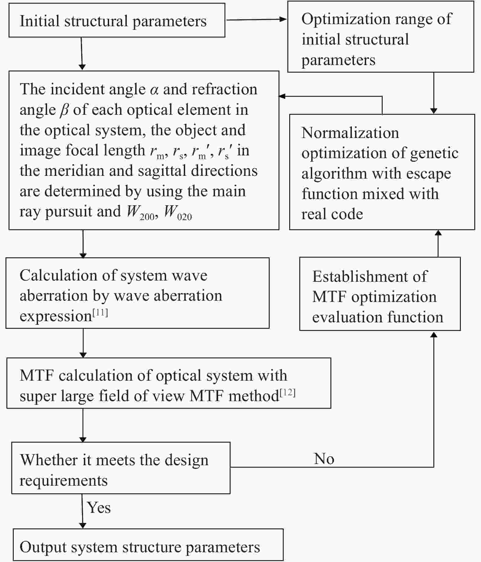
Figure 3. Flow chart of fish-eye lens system design using the sixth-order wave aberration theory
By using the sixth-order wave aberration theory, a large aperture imaging simulation of a fish-eye lens optical system is carried out, and the simulation results are compared with the numerical results of ZEMAX ray tracing. The optical parameters of the fish-eye lens system are shown in Tab.2. The monochromatic aberration distribution of visible light at five field angles of 0°, 27°, 45°, 63° and 90° is calculated respectively. It is assumed that the F-number of the fish-eye lens system is 3.2. The distance between the object point and the first optical plane is infinite at different field angles. The fish-eye lens optical system with maximum field of view angle of 180° is designed. The Optical path diagram of the optical system is shown in Fig.4.
Table 2. Optical parameters of fish-eye lens system
Surface
No.Radius of
curvature/mmThickness/
mmGlass Clear diameter/
mmObject Infinity Infinity − − 1 133 20 − 193.2188 2 113.6006 24 H-LAF52 133.5434 3 21.2604 21.3598 − 42.5158 4 212.5634 14.9998 H-LAF6LA 40.4013 5 18.6054 8.6801 − 24.5525 6 −23.3482 7.9816 H-ZK7 24.3792 7 −151.8651 10.7462 H-ZF3 27.5062 8 −61.2174 0.2868 − 30.2412 9 −67.4453 9.5701 H-ZF6 30.3071 10 −47.9643 3.2664 − 32.6737 11 127.1637 15.0004 H-LAF3B 32.2762 12 −83.7291 35.0010 − 30.4971 13 (STO) Infinite 0.1976 − 10.0882 14 448.1495 1.9986 H-ZK14 10.2155 15 −42.4732 0.1993 − 10.7582 16 54.5847 8.6472 H-QK3L 11.0715 17 −17.1825 1.9988 H-ZF6 12.4013 18 −51.6904 0.3922 − 13.1415 19 563.3054 10.0301 H-KF6 13.3806 20 −17.1944 0.1988 − 14.8488 21 −18.5197 5.8883 H-LAFL5 14.7652 22 21.2408 8.3961 H-QK3L 16.9785 23 −26.0496 1.5939 − 19.2195 24 90.2547 11.9746 H-ZF6 20.5244 25 −40.54 10 − 21.3152 Image Infinity − − 18.0099 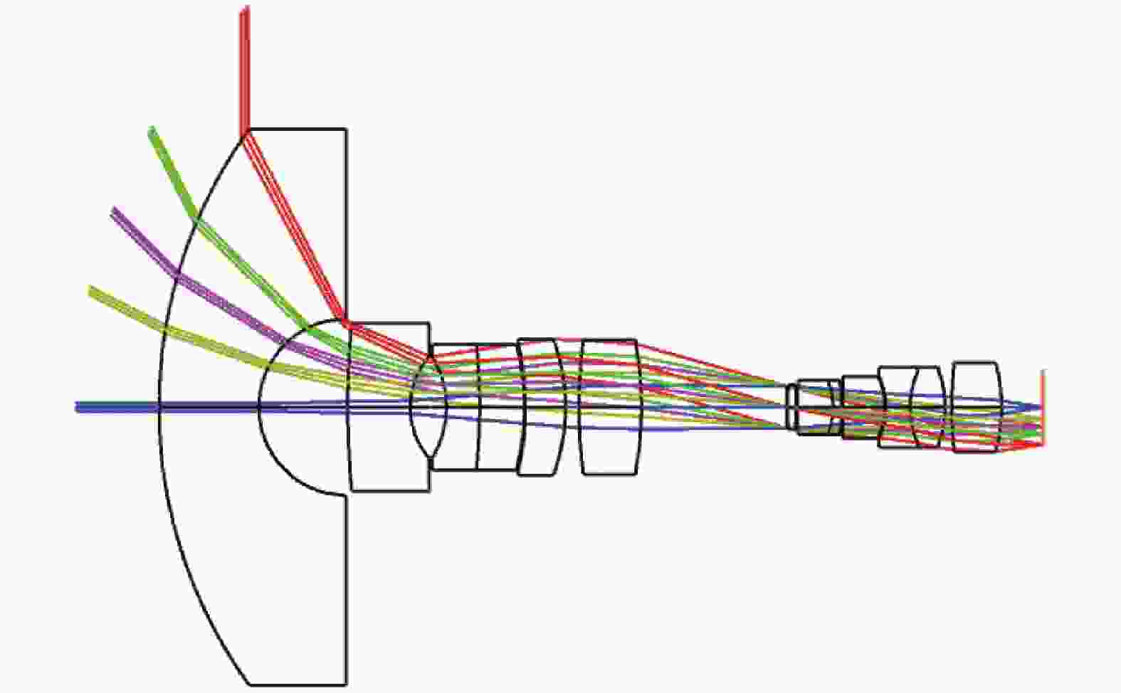
Figure 4. Optical path diagram of fish-eye lens optical system
In order to improve the accuracy of aberration calculation, it is necessary to consider the sixth-order wave aberration and more accurate pupil coordinate transfer processing. Through the calculation and analysis of this fish-eye lens systems similar to the above cases, the results show that the wave aberrations correction including higher-order aberrations and the second-order accuracy of pupil coordinates significantly improves the accuracy of aberrations calculation[11], which is related to the specific design of the system.
It is also an auxiliary method to verify the wave aberration theory to analyze whether the simplified results of aberration expression in processing paraxial optical system are consistent with the previous results. In the sixth-order wave aberration theory, if
$ \alpha ={180}^{ \circ } $ ,$\; \beta ={0}^{ \circ }, $ and the optical surface is a sphere, it represents the aberration of the object point on the axis of the axisymmetric optical system. As a result, the fourth-order intrinsic wave aberration coefficient is the same as that of Seidel, the third-order and fifth-order are zero, the sixth-order intrinsic wave aberration coefficient is the same as that of w060 reported in reference[13]. Moreover, the expression of the aberration in the direction of meridian and sagittal also becomes the same, which conforms to the geometric symmetry with axial symmetry optical system. -
The modulation transfer function (MTF) curve is not only related to the optical systems aberrations, but also to the diffraction effects of optical systems. It has the advantages of objectivity and reliability to evaluate the imaging quality of optical systems. It can be applied to optical systems with small aberrations and optical systems with large aberrations at the same time.
Figure 5 shows the fish-eye lens system with the focal length of 5.989 mm and 180° FOV angle. The modulus of the OTF is no less than 0.561 in full FOV when the spatial frequency is 60 lp/mm.
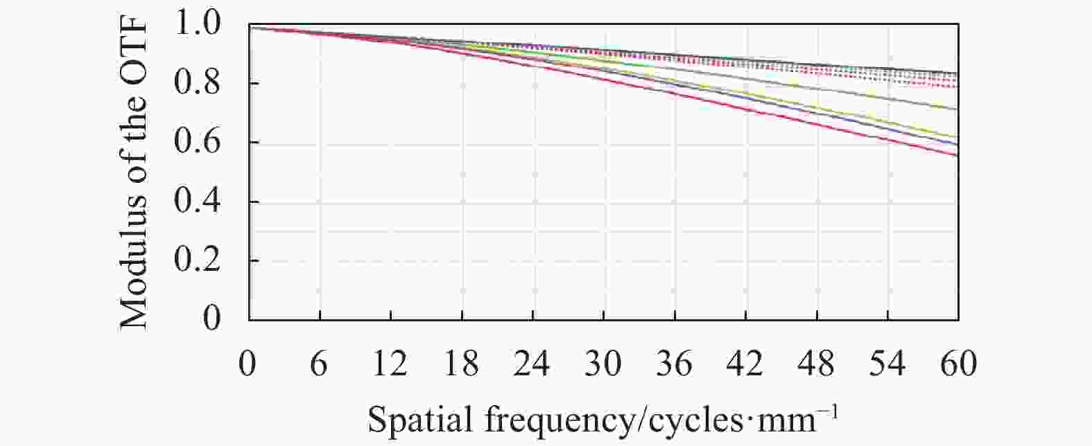
Figure 5. MTF curves of fish-eye lens system with 5.989 mm focal length and 180° FOV angle
This fish-eye lens system can satisfy the requirement of minimum the modulus of the OTF 0.561 when the spatial frequency is 60 lp/mm, and the MTF curve is smooth, and the imaging quality of the edge and central FOV is better guaranteed. The imaging quality can be maintained stably, and the imaging effect of millions of pixels of resolution can be obtained[14].
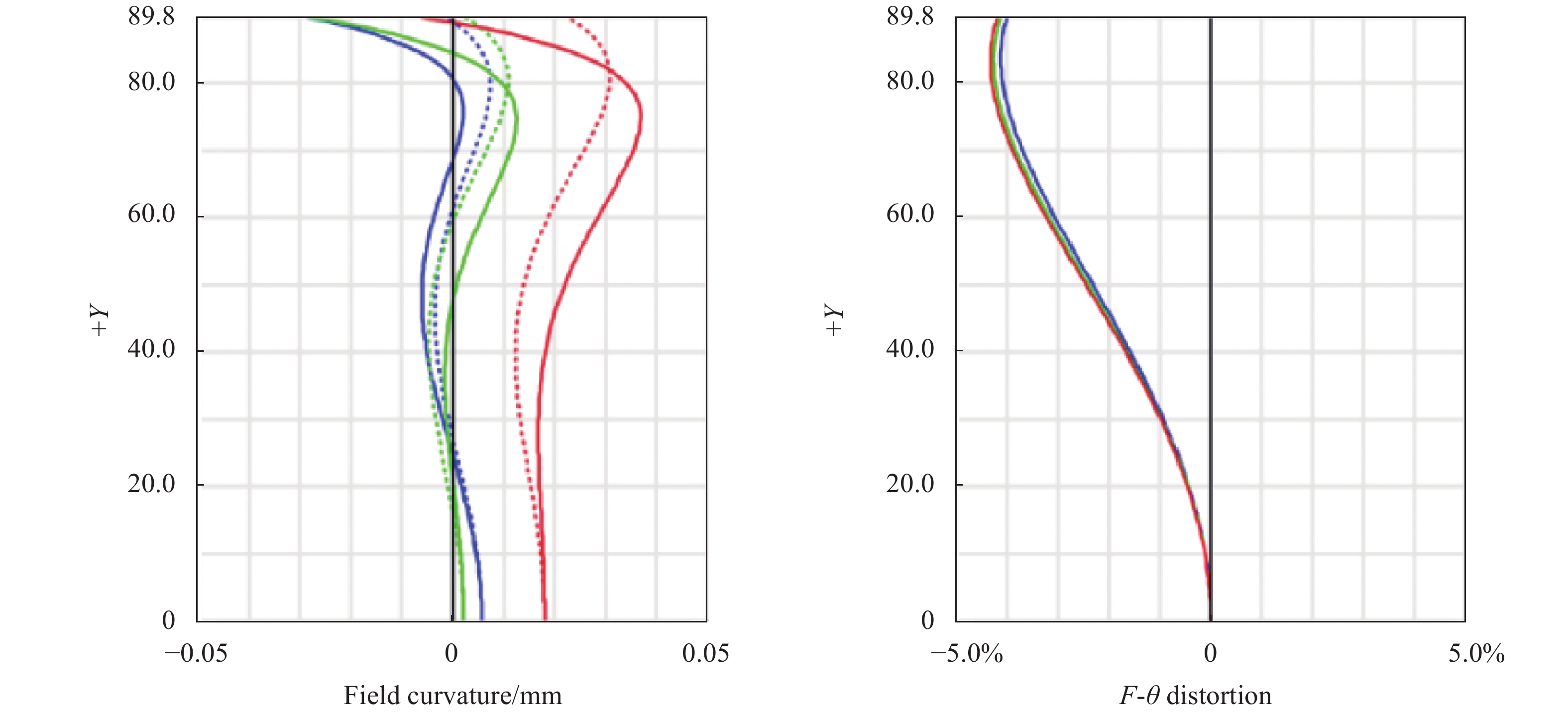
Figure 6 shows the field curvature and distortion curves of the fish-eye system at focal lengths of 5.989 mm. It can be seen that the absolute field curvature of all FOV does not exceed 0.037 mm, and the maximum distortion of all the field of view is 4.34%.
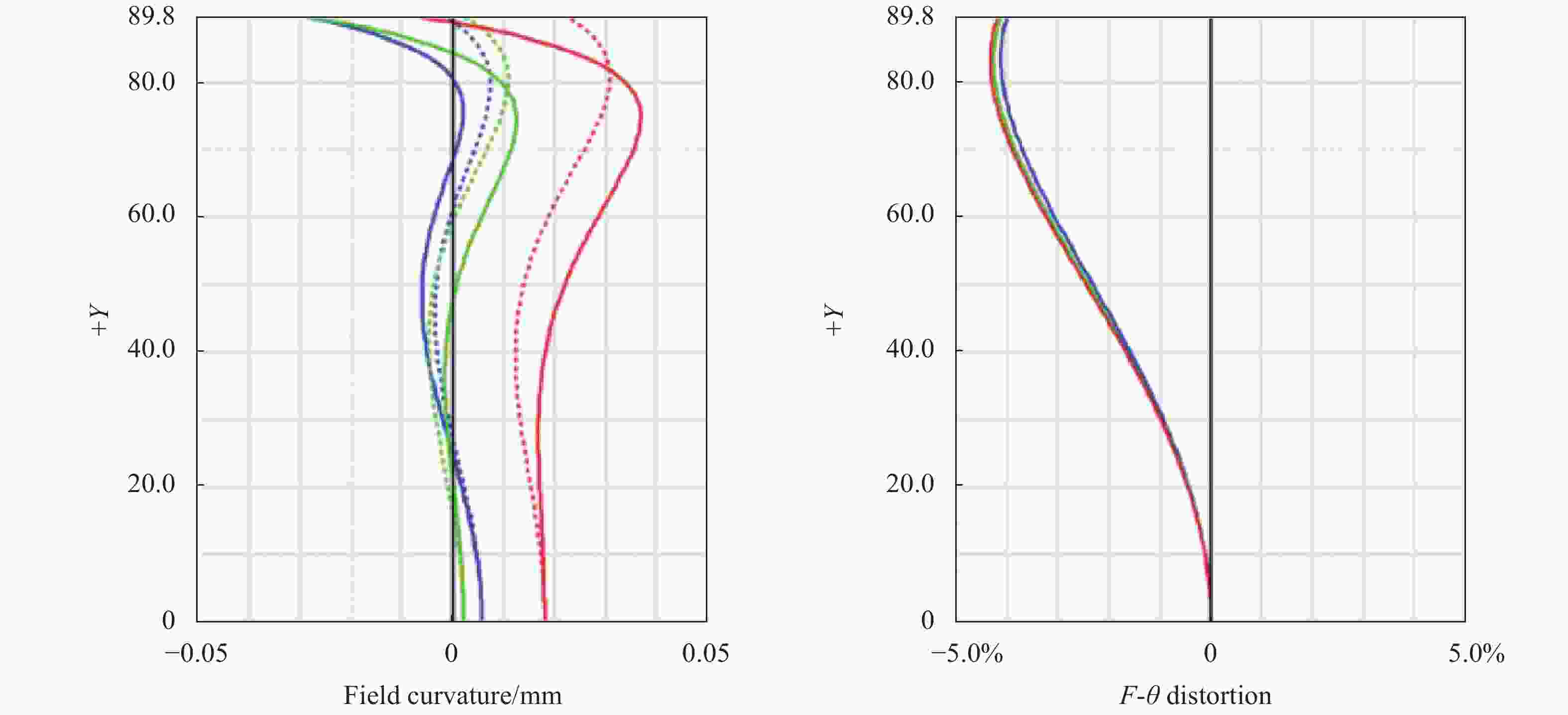
Figure 6. Field curvature (a) and F-θ distortion curves (b) of fish-eye lens system with 5.989 mm focal length and 180° FOV angle
For a panoramic lens, the distortion itself is very large. Such a large distortion can produce special imaging effects in practical application. Large distortion is in high demand in some specialized fields. Such a large distortion can be further corrected[5, 15].
Figure 7 shows the relative illumination curve of the fish-eye lens system at focal lengths of 5.989 mm. Comprehensive analysis shows that the relative illumination of the edge is no less than 0.9, which is mainly due to the decrease of the edge illumination due to the setting of the vignetting coefficient. The uniformity of the image surface illumination is very good. The system guarantees the uniformity of illumination of the image plane and the problem of illumination attenuation caused by a large FOV has been solved.
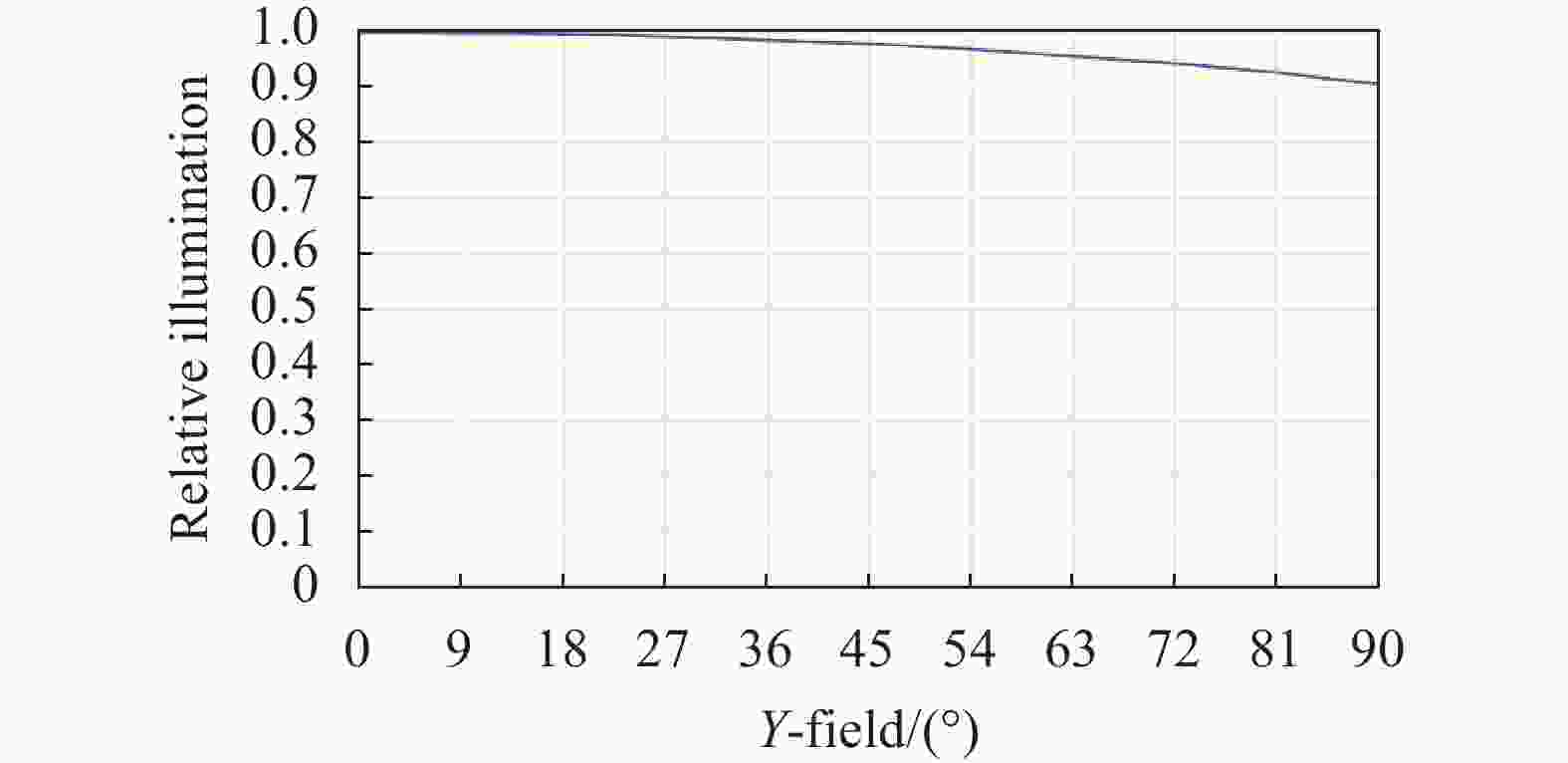
Figure 7. Relative illumination curve
-
The method by developing the derivative wave aberration of plane symmetric optical system is given, that is different from the method by developing the derivative wave aberration of paraxial optical system, and its calculation expression is given. The large aperture imaging for such system is put forward, whose pupil coordinates are in the adjacent optical plane. In order to meet the accuracy requirement of wave aberration calculation, the second-order polynomial relation is used to deal with the transfer between them. The results show that the sixth-order wave aberration can objectively reflect the pupil aberration of large aperture imaging in this kind of fish-eye lens system.
The aberration expression is not a function of the field angle, it reflects the pupil aberration of each field object point, but it cannot be used to calculate the field aberration directly, such as the field curvature aberration. We use the main ray transfer equation to calculate the parameters of the main ray, and then calculate the field curvature aberration on the image surface from the geometric relationship, and then transmit it to the corresponding wave aberration. The disadvantage is that we can't deal with the field curvature aberration of any single optical surface in the optical system. In addition, there are similar limitations in the treatment of axial chromatic aberration and transverse chromatic aberration. Therefore, the calculation methods of field curvature and chromatic aberration to overcome the above limitations need to be further explored.
The sixth-order wave aberration theory should be further explored to study the laws of large aperture imaging for such fish-eye lens optical systems, including the balance between derived aberration and intrinsic aberration, and the relationship between optical system structure and parameters. The design laws of such fish-eye lens optical systems, including the balance between derived aberration and systems should be summarized, and the new fish-eye lens system should be developed.
-
摘要: 鱼眼镜头系统具有平面对称、超大视场、大孔径成像等特点,使得其设计十分复杂。波像差理论是研究光学系统的重要手段,由于鱼眼镜头系统具有平面对称的成像特性,赛德尔初级像差和基于轴对称光学系统发展的高阶像差理论不再适用于鱼眼镜头系统的像差分析和设计。介绍了六阶波像差理论,包括六阶本征波像差、五阶像差、衍生波像差及孔径光线二阶精度对波像差的影响,给出六阶波像差理论设计鱼眼镜头系统的流程图,应用六阶波像差理论设计鱼眼镜头前光组,由其前光组与后光组像差平衡设计了后光组。最后得到一成像质量良好的鱼眼镜头系统,该镜头的焦距为5.989 mm,视场角为180°,相对孔径为1/3.2。设计结果表明,该鱼眼镜头系统的调制传递函数(MTF)数值在空间频率为60 lp/mm时均不低于0.56,具有较好的成像质量。Abstract: The fish-eye lens system has the characteristics of plane symmetry, large field of view and large aperture imaging. That makes fish-eye lens design very complicated. Wave aberration theory is an important means to study optical system. Because the fish-eye lens system has the imaging characteristics of plane symmetry, Seidel primary aberration and higher-order aberration theory based on axisymmetric optical system are no longer suitable for aberration analysis and design of the fish-eye lens systems. The theory of sixth-order wave aberration was introduced, including the sixth-order intrinsic wave aberrations, the fifth-order aberration, transverse aberrations and the influence of the second-order accuracy of the aperture ray on the wave aberration. The flow chart of fish-eye lens system design based on sixth-order wave aberration theory was given. The former optical group of fish eye lens was designed based on sixth-order wave aberration theory, and the latter optical group design was obtained by balancing the aberrations of former group and latter group. Finally, a fish-eye lens system with good imaging quality was obtained. Its focal length is 5.989 mm, its field of view angle (FOV) is 180°, and its relative aperture is 1/3.2. The design results show that the modulation transfer function (MTF) of the fish-eye lens system is no less than 0.56 when the spatial frequency is 60 lp/mm. This fish-eye lens system has better imaging quality.
-
Figure 1. Optical scheme of an aperture ray P0P1P2 passing through a double-element optical system
Figure 2. Coordinate systems of the wave surface and the image plane in the reverse optical path of a double-element optical system
Figure 3. Flow chart of fish-eye lens system design using the sixth-order wave aberration theory
Figure 5. MTF curves of fish-eye lens system with 5.989 mm focal length and 180° FOV angle
Figure 6. Field curvature (a) and F-θ distortion curves (b) of fish-eye lens system with 5.989 mm focal length and 180° FOV angle
Table 1. Design specifications
Parameter Value Focal length/mm ≥5 F number ≤3.5 FOV/(°) 180 Design spectrum Visible light (F, D, C) Maximum lens clear aperture/mm ≤100 Object location At infinity  下载: 导出CSV
Table 2. Optical parameters of fish-eye lens system
Surface
No.Radius of
curvature/mmThickness/
mmGlass Clear diameter/
mmObject Infinity Infinity − − 1 133 20 − 193.2188 2 113.6006 24 H-LAF52 133.5434 3 21.2604 21.3598 − 42.5158 4 212.5634 14.9998 H-LAF6LA 40.4013 5 18.6054 8.6801 − 24.5525 6 −23.3482 7.9816 H-ZK7 24.3792 7 −151.8651 10.7462 H-ZF3 27.5062 8 −61.2174 0.2868 − 30.2412 9 −67.4453 9.5701 H-ZF6 30.3071 10 −47.9643 3.2664 − 32.6737 11 127.1637 15.0004 H-LAF3B 32.2762 12 −83.7291 35.0010 − 30.4971 13 (STO) Infinite 0.1976 − 10.0882 14 448.1495 1.9986 H-ZK14 10.2155 15 −42.4732 0.1993 − 10.7582 16 54.5847 8.6472 H-QK3L 11.0715 17 −17.1825 1.9988 H-ZF6 12.4013 18 −51.6904 0.3922 − 13.1415 19 563.3054 10.0301 H-KF6 13.3806 20 −17.1944 0.1988 − 14.8488 21 −18.5197 5.8883 H-LAFL5 14.7652 22 21.2408 8.3961 H-QK3L 16.9785 23 −26.0496 1.5939 − 19.2195 24 90.2547 11.9746 H-ZF6 20.5244 25 −40.54 10 − 21.3152 Image Infinity − − 18.0099
下载: 导出CSV
-
[1] Hou Guozhu, Lu Lijun. Design of large aperture zoom projection lens [J]. Journal of Applied Optics, 2018, 39(3): 405-411. [2] Wang Yongzhong. Fisheye Lens Optics[M]. Beijing: China Science Publishing and Media, 2006. (in Chinese) [3] Kidger M J. Intermediate Optical Design [M]. US: SPIE Press, 2004. [4] Dai Jianning. The imaging theory and the optimization design of fisheye lens [D]. Changsha: National University of Defense Technology, 1999: 27-30. (in Chinese) [5] Lv Lijun, Wu Xuewei. Design of initial structure of fisheye lens [J]. Acta Optica Sinica, 2017, 37(2): 0208001. (in Chinese) [6] Lv Lijun. Aberration theory of plane-symmetric grating systems [J]. Synchrotron Radiat, 2008, 15: 399-410. doi: 10.1107/S0909049508003658 [7] Lv Lijun, Hu Xiaoyan, Sheng Cuiyuan. Optimization method for ultra-wide-angle and panoramic optical systems [J]. Appl Opt, 2012, 51: 3776-3786. doi: 10.1364/AO.51.003776 [8] Wynne C G. Primary aberrations and conjugate change [J]. Proceedings of the Physical Society: Section B, 1952, 65(6): 429-437. doi: 10.1088/0370-1301/65/6/306 [9] Hopkins H H. The development of image evaluation methods[C]//SPIE Proc, 1974, 46: 2-18. [10] Hou Guozhu, Lv Lijun. Design of ultra wide-angle photographic objective based on ZEMAX [J]. Journal of Applied Optics, 2016, 37(3): 441-445. doi: 10.5768/JAO201637.0305002 [11] Lv Lijun, Cao Yiqing. Sixth-order wave aberration theory of ultra-wide-angle optical systems [J]. Appl Opt, 2017, 56: 8570-8583. doi: 10.1364/AO.56.008570 [12] Jia Han, Lv Lijun, Cao Yiqing. Modulation transfer function of a fish-eye lens based on the sixth-order wave aberration theory [J]. Appl Opt, 2018, 57(2): 314-321. doi: 10.1364/AO.57.000314 [13] Hoffman J M. Induced aberrations in optical systems[D]. US: University of Arizona, 1993. [14] Hou Guozhu, Lv Lijun. Design of zoom fish-eye lens systems [J]. Infrared and Laser Engineering, 2020, 49(7): 20190519. (in Chinese) [15] Lv Lijun, Liu Meng, Shi Ye. Correction method of image distortion of fisheye lens [J]. Infrared and Laser Engineering, 2019, 48(9): 0926002. (in Chinese) doi: 10.3788/IRLA201948.0926002 -

 点击查看大图

计量
- 文章访问数: 394
- HTML全文浏览量: 126
- PDF下载量: 49
- 被引次数: 0


