


-
我国海洋面积辽阔,海洋中蕴含着丰富的资源,对于海洋环境的检测,关系到我国海洋事业发展的可持续性,成为我国综合国力的竞争指标之一。在石油开发和运输过程中,海面石油开采平台和输油管道的机械故障或爆裂等因素,将会导致海面溢油事件频繁发生。石油泄漏事故不仅破坏了大气环境和生态平衡,而且还造成大量海洋生物死亡,给经济造成严重损失;如若油污进入沿海湿地、红树林、海洋生物保护区,将会造成生态环境的破坏,导致生物多样性下降;再者,原油是多种液态氢中的苯及其衍生物,会导致人类反应迟钝,昏迷,甚至造成较高的癌症发病率,严重威胁人体健康。因此在石油泄露后,急需对海面溢油的情况进行建模分析,得出探测器的最佳观测角以及区分海水和油膜的关键指标,这将为今后海水溢油污染的识别和监测积累理论基础,以便制定适当的应对措施清理海面油膜。
传统的机载探测技术主要局限于垂直收集海面油膜等目标场景的光强度信息[1]。近年来,一方面高光谱技术的应用,将探测获取的海面溢油等目标的信息从空间维度扩展到光谱维度[2]。另一方面,多角度探测技术的发展又将目标信息维度扩展到多角度维度[3]。除了强度、光谱和多角度探测方式外,在探测海面目标的反射辐射中,还存在偏振维度信息,利用偏振探测技术监测海洋溢油有三个优点:第一,偏振成像具有良好的除雾特性[3],可以降低海面雾气等环境因素对偏振探测的影响;第二,偏振探测能够减少杂波影响,一定程度地增强海面目标场景的对比度[4];第三,偏振探测能够削弱海面产生的太阳耀光对观测角度的限制[5]。另外,相关研究表明海面油膜的偏振探测受太阳入射角度、观测角度的影响[6]。但是针对这些因素对粗糙海面海水和油膜的偏振双向反射率因子的影响还没有相关文献进行具体仿真分析。
文中将太阳入射角度和观测角度等因素考虑在内,主要研究海洋油膜和海水多角度偏振探测的理论和方法,为今后海水溢油污染的识别和监测积累理论基础,储备技术知识,并提供科学仪器研制经验。
-
华东石油学院等单位的研究人员对各类原油及海水的密度、折射率等参数进行多次精密的测量和标定[7],统计的原油和海水在可见光波段的折射率一般在1.44~1.56以及1.33~1.34范围内。
海面油膜的光学特性受多个因素影响:折射率会影响太阳光照射海面形成的镜面反射;油膜的分子颗粒会影响光的散射特性;海水和油膜的吸收系数差异会影响光谱反射特性;油膜的厚度不同也会导致不同的吸收。另外,海面油膜受太阳光照、海水温度差异、海水洋流流动以及海洋微生物成分的影响,其光学特性会持续性发生动态变化,这进一步加剧了海面油膜监测、识别的难度。为简化起见,文中只讨论折射率差异。
-
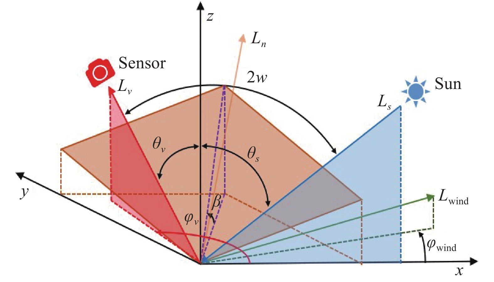
真实的海平面一般粗糙不平,海面油膜介质表面产生的偏振反射分布在整个观测空间。如果要完整表征整个目标表面的多角度反射和偏振特性,需要建立偏振双向反射分布函数(pBRDF)。图1为pBRDF模型示意图。
$${F_r}({\theta _s},{\varphi _s},{\theta _v},{\varphi _v}) = \frac{{\operatorname{d} {L_{rp}}({\theta _s},{\varphi _s},{\theta _v},{\varphi _v})}}{{\operatorname{d} E({\theta _s},{\varphi _s})}}$$ (1) 式中:
${\theta _s}$ 为太阳天顶角;${\varphi _s}$ 为太阳方位角;${\theta _v}$ 为观测天顶角;${\varphi _\nu }$ 为观测方位角;$\operatorname{d} E$ 为入射辐照度;$\operatorname{d} {L_{rp}}$ 为偏振反射辐亮度。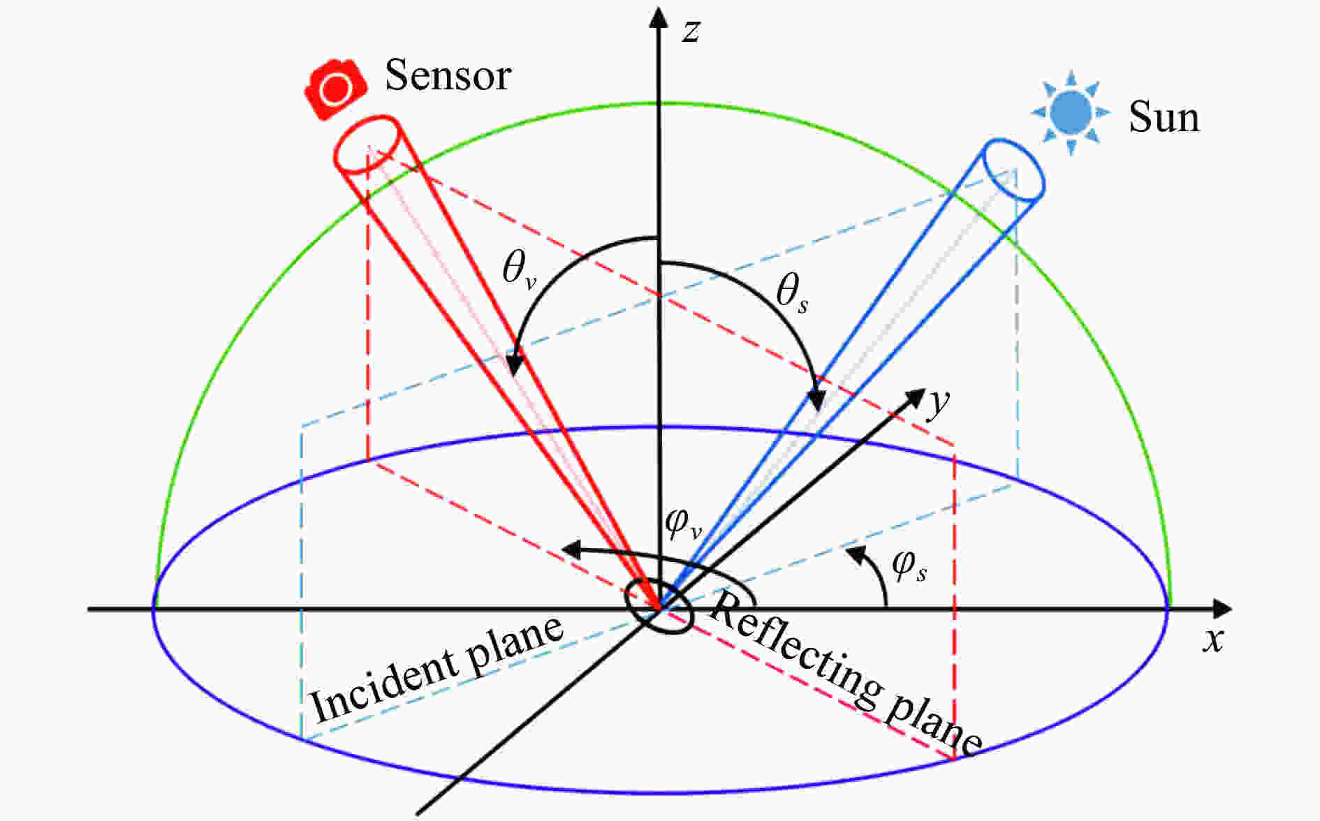
图 1 pBRDF模型示意图
Figure 1. Schematic diagram of pBRDF model
然而在实际的偏振探测中,一般使用偏振双向反射率因子(PBR)来间接地反映目标场景的偏振双向反射分布函数,PBR可以表示为:
$$R({\theta _s},{\varphi _s},{\theta _v},{\varphi _v}) = \frac{{\operatorname{d} {L_{rp}}({\theta _s},{\varphi _s},{\theta _v},{\varphi _v})}}{{\operatorname{d} L({\theta _s},{\varphi _s})}}$$ (2) 式中:R为偏振双向反射率因子;
${\rm{d}}L$ 为入射辐亮度。可以把实际的粗糙海面分解成许多各个方向倾斜、近似地服从高斯分布的微小平面。Kyu Yoshimori等人研究了海面风速与二维粗糙海面微小平面的概率分布函数之间的关系[8]。
$$P({S_{\rm{up}}},{S_{\rm{cross}}}) = \frac{1}{{2\pi {\sigma _{\rm{up}}}{\sigma _{\rm{cross}}}}}\exp \left( - \frac{1}{2}\left(\frac{{S_{\rm{up}}^2}}{{\sigma _{\rm{up}}^2}}{\rm{ + }}\frac{{S_{{\rm{\rm{c}}ross}}^2}}{{\sigma _{\rm{cross}}^2}}\right)\right)$$ (3) 式中:
${S_{\rm{up}}}$ 、${S_{\rm{cross}}}$ 分别为倾斜微小平面逆风和侧风方向的斜率;${\sigma _{\rm{up}}}$ 、${\sigma _{\rm{cross}}}$ 分别为倾斜微小平面逆风和侧风方向斜率的RMS值。Scripps海洋学研究所得出海水和油膜的粗糙度与风速分别满足如下关系[9]。
$$\left\{ \begin{aligned} & \sigma _{\rm{up,water}}^2 = 0.000 + 0.003\;16 \times v \pm 0.004 \\ & \sigma _{\rm{cross,water}}^2 = 0.003 + 0.001\;92 \times v \pm 0.002 \end{aligned} \right.$$ (4) $$\left\{ \begin{aligned} & \sigma _{\rm{up,oil}}^2 = 0.005 + 0.007\;8 \times v \pm 0.002 \\ & \sigma _{\rm{cross,oil}}^2 = 0.003 + 0.008\;4 \times v \pm 0.002 \end{aligned} \right.$$ (5) 倾斜微平面单元坐标如图2所示,以倾斜的微小面元上的入射点和反射点为坐标原点,
$x$ 轴、$z$ 轴分别表示方位角、天顶角基准轴;太阳光入射面与平面$oxz$ 重合;${L_{\rm{wind}}}$ ,${L_n}$ 分别表示海风风向和倾斜微平面单元的法线方向;${L_{\rm{s}}}$ ,${L_\nu }$ 分别表示太阳光线入射角度和探测器观测角度;$w$ 表示太阳照射海面微平面单元的入射角度和反射角度;$\beta $ 表示海面倾斜微面元与平面$oxy$ 的夹角。
图 2 倾斜微平面单元坐标示意图
Figure 2. Coordinate diagram of inclined micro plane element
海面倾斜微平面单元在
$x$ 和$y$ 方向的斜率${S_x}$ ,${S_y}$ 与天顶角以及方位角的关系分别满足下式:$${S_x} = \frac{{ - (\sin {\theta _s} + \sin {\theta _v}\cos {\varphi _v})}}{{\cos {\theta _s} + \cos {\theta _v}}}$$ (6) $${S_y} = \frac{{\sin {\theta _v}\sin {\varphi _v}}}{{\cos {\theta _s} + \cos {\theta _v}}}$$ (7) 海面倾斜的微小面元的倾斜角度
$\beta $ 与方向斜率${S_x}$ ,${S_y}$ 的关系可以表示为:$${\tan ^2}\beta = S_x^2 + S_y^2$$ (8) 粗糙海面微平面单元的概率分布函数关于风速不对称,逆风方向和侧风方向的斜率与小平面体
$x$ 和$y$ 的方向斜率${S_x}$ ,${S_y}$ 满足如下关系:$${S_{\rm{up}}} = {S_x}\cos {\varphi _{\rm{wind}}} + {S_y}\sin {\varphi _{\rm{wind}}}$$ (9) $${S_{\rm{cross}}} = {S_y}\cos {\varphi _{\rm{wind}}} - {S_x}\sin {\varphi _{\rm{wind}}}$$ (10) 海面微平面单元的反射角
$w$ 满足下式:$${\rm{cos}}2w = = \cos {\theta _s}\cos {\theta _v} + \sin {\theta _s}\sin {\theta _v}\cos {\varphi _v}$$ (11) 针对太阳光经过海面介质反射后的偏振分量变化可用菲涅尔反射方程表示:
$$ r_{P}=\frac{n_{2} \cos \theta_{i}-n_{1} \cos \theta_{t}}{n_{2} \cos \theta_{i}+n_{1} \cos \theta_{t}}=\frac{\tan \left(\theta_{i}-\theta_{t}\right)}{\tan \left(\theta_{i}+\theta_{t}\right)} $$ (12) $$ r_{S}=\frac{n_{1} \cos \theta_{i}-n_{2} \cos \theta_{t}}{n_{1} \cos \theta_{i}+n_{2} \cos \theta_{t}}=\frac{\sin \left(\theta_{i}-\theta_{t}\right)}{\sin \left(\theta_{i}+\theta_{t}\right)} $$ (13) 式中:rp为P波反射系数;rs为S波反射系数;n1为空气折射率;n2为海面或油膜介质折射率;
${\theta _i}$ 为入射角;${\theta _t}$ 为折射角。联立公式(2)至公式(13),最终推算出归一化的粗糙海水以及油膜表面的偏振分量反射率。
$$ \left\{ {\begin{aligned} & {R_{P,\rm{water}}}\left( {{\theta _s},{\theta _v},{\phi _v},{\phi _{{\rm{\rm{wind} }}}},{n_{\rm{water}}},v} \right)\\ & \quad = \frac{{r_{P,\rm{water}}^2(w) \cdot {P_{\rm{water}}}\left( {{S_{\rm{up}}},{S_{\rm{cross}}}} \right)}}{{4{{\cos }^4}\beta \cos {\theta _v}}}\\ & {R_{S,\rm{water}}}\left( {{\theta _s},{\theta _v},{\phi _v},{\phi _{{\rm{\rm{wind }}}}},{n_{\rm{water}}},v} \right) \\ & \quad= \frac{{r_{S,\rm{water}}^2(w) \cdot {P_{\rm{water}}}\left( {{S_{\rm{up}}},{S_{\rm{cross}}}} \right)}}{{4{{\cos }^4}\beta \cos {\theta _v}}} \end{aligned}} \right. $$ (14) $$ \left\{ {\begin{aligned} & {{R_{P,\rm{oil}}}\left( {{\theta _s},{\theta _v},{\phi _v},{\phi _{{\rm{\rm{wind} }}}},{n_{\rm{oil}}},v} \right) = \frac{{r_{P,{\rm{ }}\rm{oil}}^2(w) \cdot {P_{\rm{oil}}}\left( {{S_{\rm{up}}},{S_{\rm{cross}}}} \right)}}{{4{{\cos }^4}\beta \cos {\theta _v}}}}\\ & {{R_{S,\rm{oil}}}\left( {{\theta _s},{\theta _v},{\phi _v},{\phi _{{\rm{\rm{wind }}}}},{n_{\rm{oil}}},v} \right) = \frac{{r_{S,\rm{oil}}^2(w) \cdot {P_{\rm{oil}}}\left( {{S_{\rm{up}}},{S_{\rm{cross}}}} \right)}}{{4{{\cos }^4}\beta \cos {\theta _v}}}} \end{aligned}} \right. $$ (15) 式中:Rp,water、Rs,water、Rp,oil、Rs,oil分别为海水和油膜的p光和s光的偏振反射率因子;rp,water、rs,water、rp,oil、rs,oil分别为海水和油膜的p光和s光的菲涅尔反射系数。
可见粗糙海面的偏振双向反射率与太阳入射天顶角等多个物理参量均有关系。因此,在数值仿真时需要分别讨论单一变量对粗糙海面和海面油膜的偏振双向反射率因子的影响。另外,在数值仿真中,文中忽略大气传输链路中的大气散射光对偏振反射分量的影响。
-
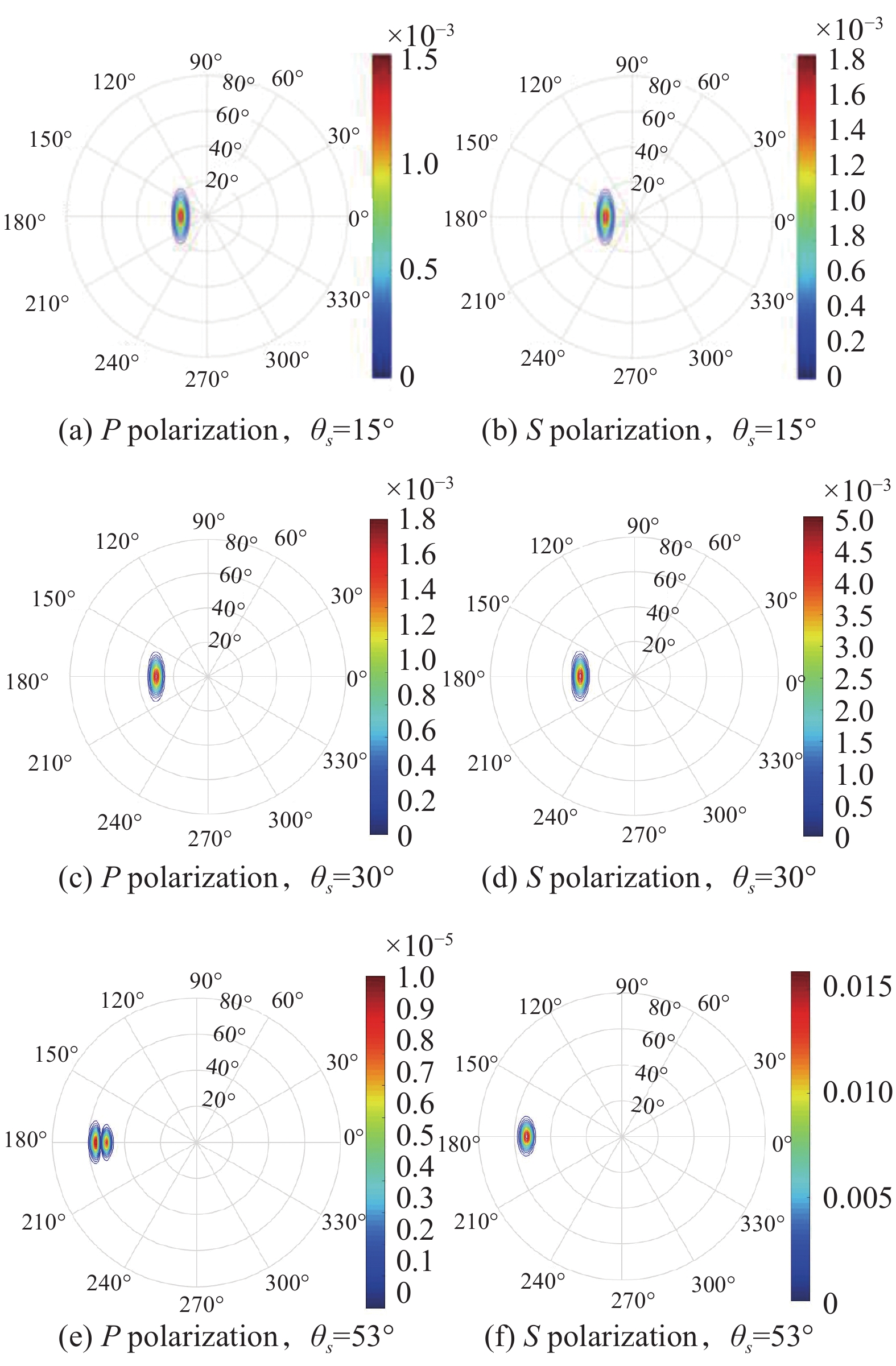
设定初始参数包括海面风速为1 m/s,风向为0º,太阳方位角为0º,海面海水的折射率为1.33。分别仿真太阳天顶角在15º、30º和53º角度下,海面海水在
$2\pi $ 观测空间的偏振反射率分布情况。如图3所示,仿真结果表明,当太阳天顶角为海水的布儒斯特角(约为53º)时,$2\pi $ 空间内P偏振反射率峰值出现极小值1.0×10⁻⁵,在观测空间的分布不完全为零。对于S偏振反射率,随着太阳天顶角度从15º增加到53º,始终保持增长趋势。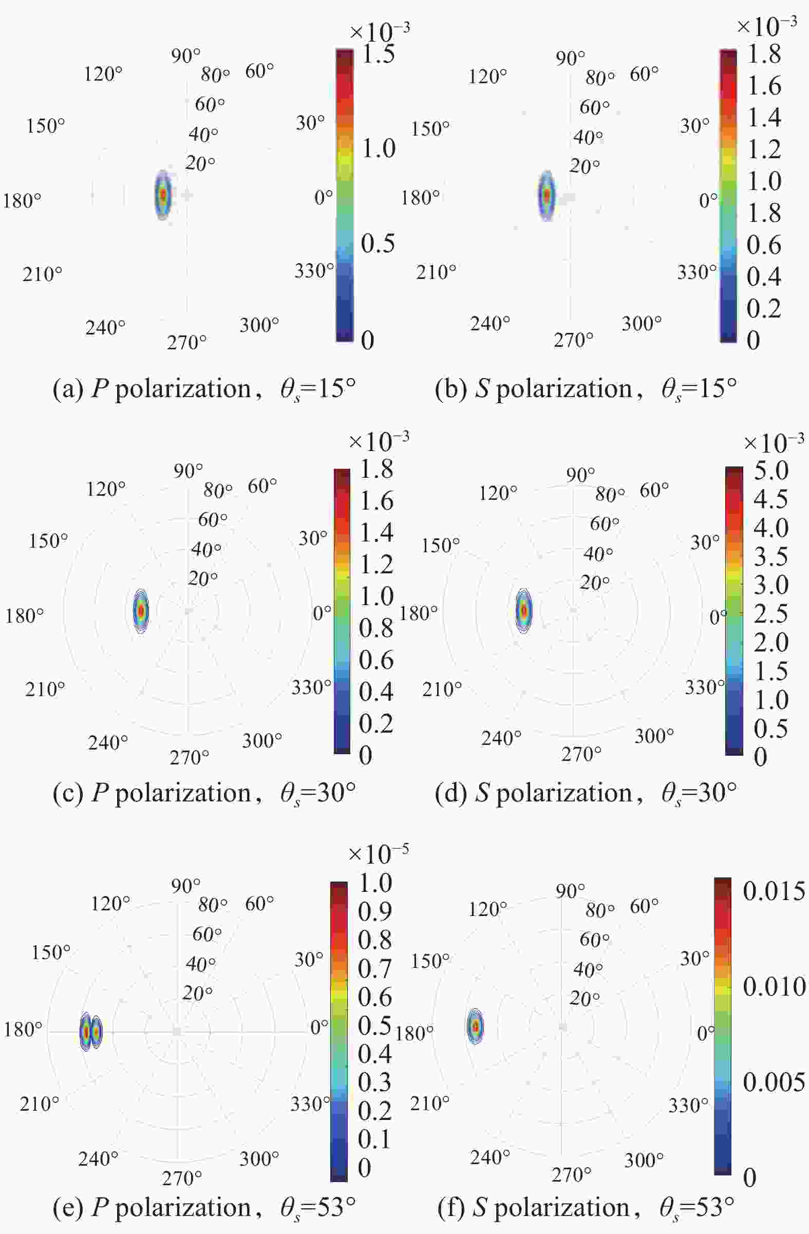
图 3 粗糙海面海水偏振双向反射率分布(不同太阳天顶角)
Figure 3. Distribution of bidirectional reflectance of water polarization in rough sea (different solar zenith angles)
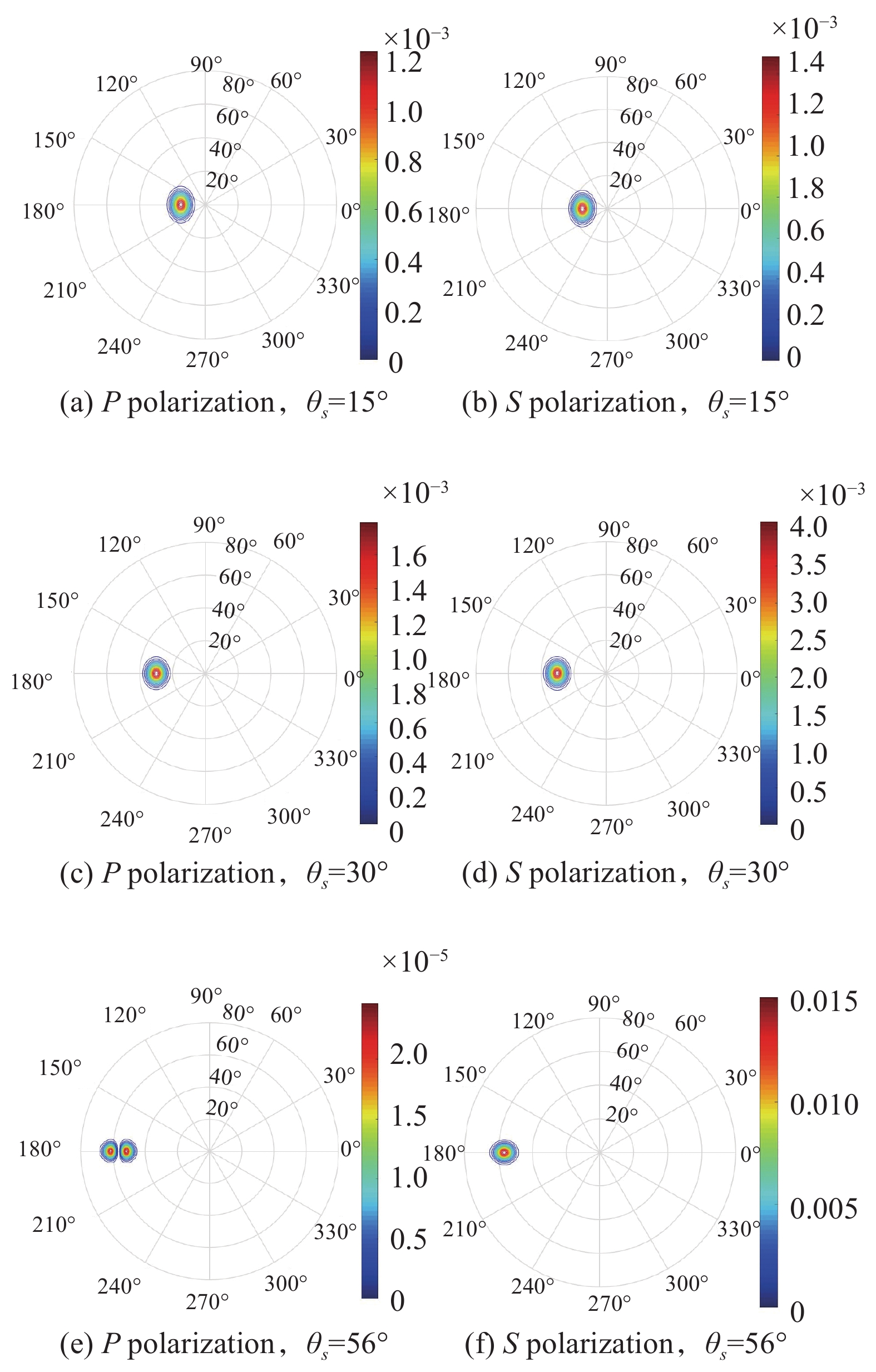
同理,对粗糙海面油膜在不同太阳天顶角入射下的偏振反射率进行数值仿真,仿真过程与其类似。设置与海面海水相同的初始参数,不同的是油膜折射率为1.5。分别仿真太阳天顶角为15º、30º、56º时,海面油膜在
$2\pi $ 观测空间的偏振反射率分布情况。如图4所示,P偏振反射率峰值在56°时出现极小值点2.5×10⁻⁵;而随着太阳天顶角增大,S偏振分量保持上升趋势。对比可以看出两种介质的偏振反射率随太阳入射角度变化的趋势大致相同,但是在极值处的坐标点和偏振反射率数值大小以及空间分布形状上均存在明显差别。
图 4 粗糙海面油膜偏振双向反射率分布(不同太阳天顶角)
Figure 4. Bidirectional reflectance distribution of oil film polarization at rough sea surface (different solar zenith angles)
-
设置初始参数包括海面油膜折射率为1.5,太阳天顶角为30º,风向为0º。分别计算风速为1、5、10、20 m/s时,海面油膜的S偏振双向反射率分布函数。
如图5所示,当风速从1 m/s逐步增大到20 m/s时,偏振反射率峰值大小从4.0×10−3降低到1.2×10−3。仿真结果显示,随着海面风速的增快,偏振反射率在
$2\pi $ 观测空间的有效反射区域逐渐扩大,且偏振反射率峰值显著降低。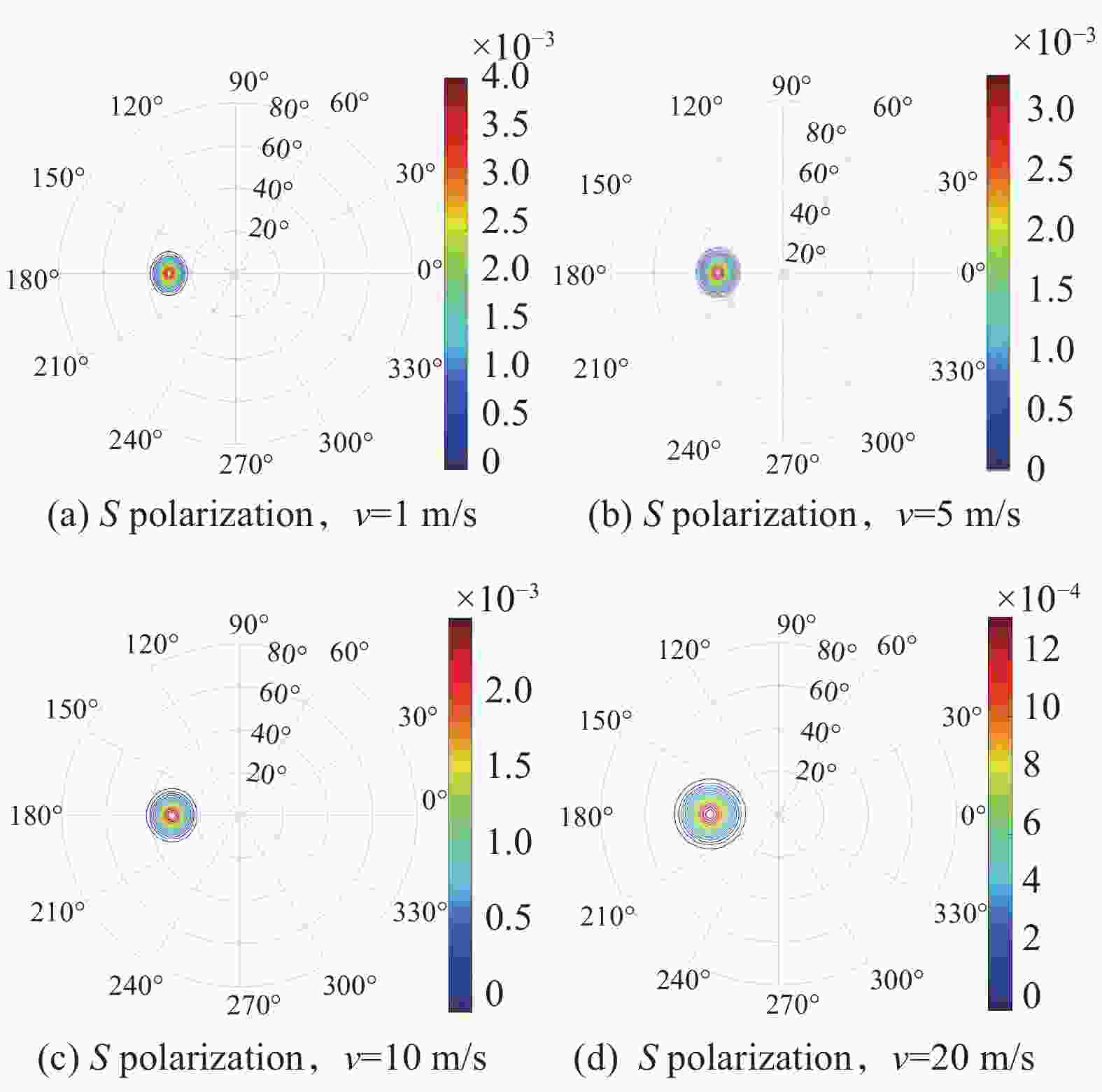
图 5 粗糙海面油膜的S偏振反射率分布(不同风速)
Figure 5. S polarization reflectance distribution of oil film at rough sea surface (different wind speeds)
-
设置初始参量包括海面油膜的折射率为1.50,太阳天顶角为30º,海面风速为1 m/s。分别仿真海面风向为0º、30º、60º和90º时,粗糙海面油膜在
$2\pi $ 观测空间的S偏振反射率分布情况。如图6所示,当海面风向从0º逐渐旋转到90º的过程中,S偏振双向反射率在$2\pi $ 观测空间的分布的旋转方向与海面风向的旋转方向相同,偏振反射率峰值几乎不变。
图 6 粗糙海面油膜的S偏振反射率分布(不同风向)
Figure 6. Distribution of S polarization reflectance of oil film in rough sea surface (different wind direction)
-
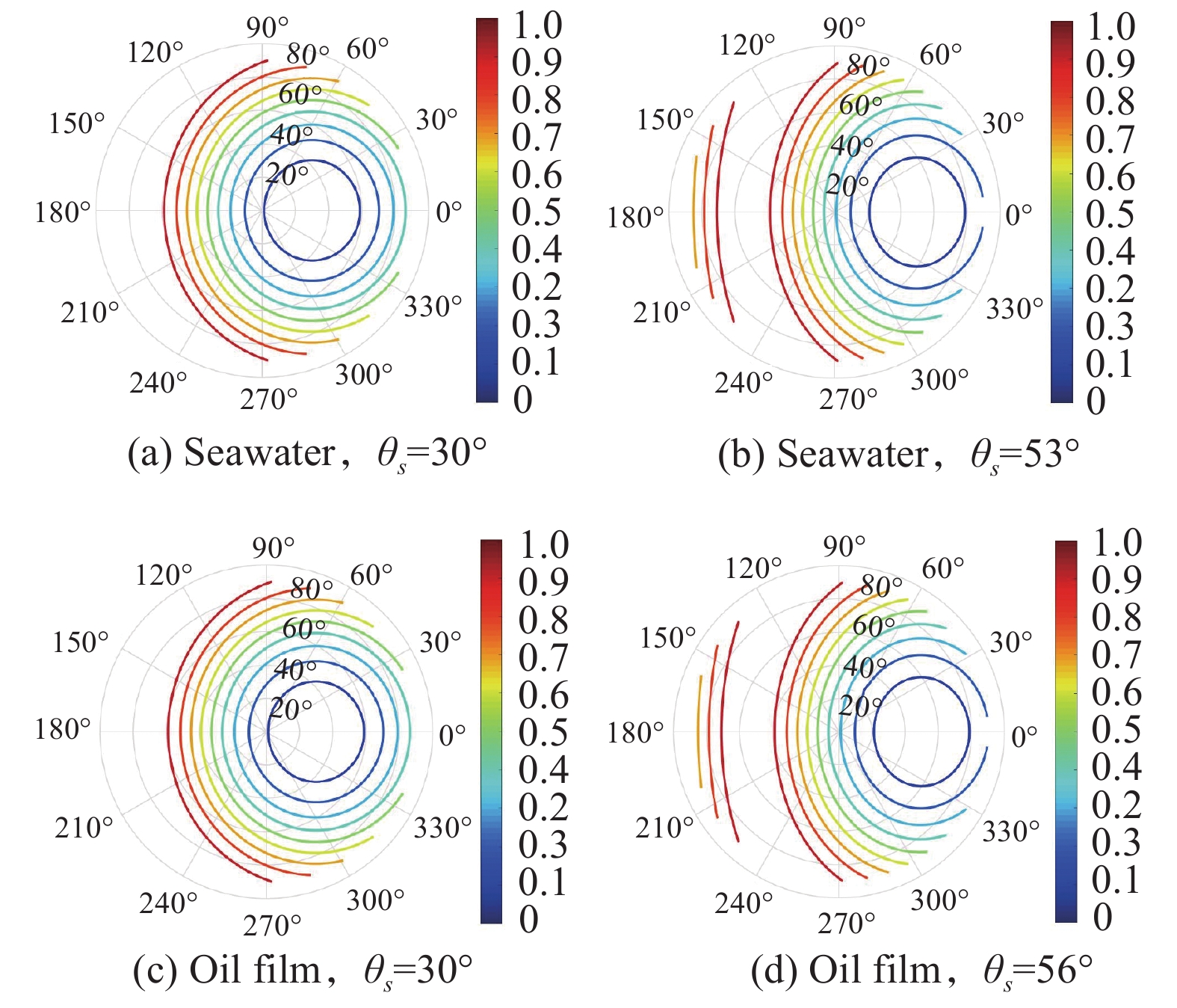
设置初始参量包括海水折射率为1.33,油膜折射率为1.5,太阳方位角为0°,海面风速1 m/s,风向0°等。分别仿真在不同太阳天顶角时,粗糙海面海水和油膜的线偏振度空间分布情况。如图7所示,仿真结果表明,当太阳天顶角以30°入射时,海水和海面油膜的线偏振度以30°观测天顶角、0°观测方位角为圆心,呈圆环状分布,且观测角度越接近圆心,线偏振度越小。当太阳天顶角以布儒斯特角入射时,海水和海面油膜的线偏振度,在偏振反射背向区域(图7(b)和图7(d)的右侧)呈同心圆环状递增分布,在偏振反射正向区域(图7(b)和图7(d)的左侧)随着观测天顶角增大而减小。
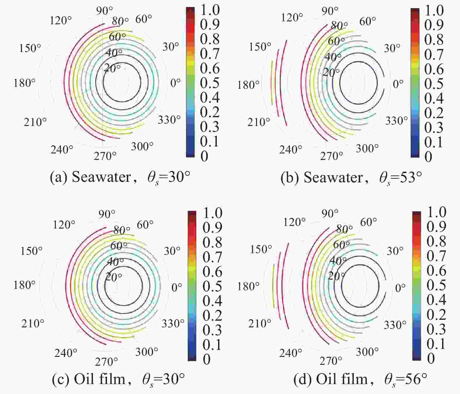
图 7 粗糙海面海水和油膜的线偏振度分布(不同太阳天顶角)
Figure 7. Distribution of linear polarization of seawater and oil film in rough sea (different solar zenith angles)
文中提出的粗糙海面pBRDF模型,主要用于预测海面偏振反射分量的分布、变化情况,便于选择最佳的偏振探测角度。为了提升目标和背景的对比度和信噪比,最好将探测仪器的观测角度贴近布儒斯特角。
-
为了验证海面油膜的偏振探测识别能力,最后进行原理性实验。实验如图8所示,相机以40°角拍摄,通过旋转镜头前偏振片的方式,分时采集四张不同起偏角度图像。图8(b~e)分别是从0°、45°、90°和135°偏振方向采集的图像。

图 8 偏振成像实验场景图以及采集的4幅海面油膜偏振图像
Figure 8. Polarization imaging experiment scene and four polarization images of oil film on the sea surface were collected
海水使用纯净水加海盐配制而成,折射率约为1.33,密度约为1.03 g/cm3;油膜使用大庆原油,折射率约1.46,密度约为0.88 g/cm3。海水油膜的容器采用黑色塑料材料,在暗室内采用卤素灯照射白色漫反射板来模拟阴天天空背景,产生非偏振光。
当光通过海面大气倾斜照射到海水及油膜表面发生反射辐射时会携带目标场景的偏振维度信息,通常采用Stokes参量来表述[10]。
$$S(x,y) = \left[ {\begin{aligned} {{S_0}(x,y)} \\ {{S_1}(x,y)} \\ {{S_2}(x,y)} \\ {{S_3}(x,y)} \end{aligned}} \right] = \left[ {\begin{aligned} I \\ Q \\ U \\ V \end{aligned}} \right] = \left[ {\begin{array}{*{20}{c}} {{I_0}(x,y) + {I_{90}}(x,y)} \\ {{I_0}(x,y) - {I_{90}}(x,y)} \\ {{I_{45}}(x,y) - {I_{135}}(x,y)} \\ {{I_{RHC}}(x,y) - {I_{LHC}}(x,y)} \end{array}} \right]$$ (16) 式中:
${I_0}$ 、${I_{45}}$ 、${I_{90}}$ 、${I_{135}}$ 分别为0°、45°、90º、135º方向线偏振光强度;${I_{LHC}}$ 、${I_{RHC}}$ 分别为左旋、右旋圆偏振光强度。大部分目标Stokes参量中的表征圆偏振分量的$V$ 为零。因此,常规的偏振系统探测线偏振态强度即可。将获取的4幅线偏振强度图像代入公式(16),可计算出Stokes分量。这里使用线偏振度描述目标场景的偏振特性,大小表征了目标场景线偏振度的高低。线偏振度(DoLP)[10]可以用Stokes参量表示:
$$DoLP = \frac{{\sqrt {{Q^2} + {U^2}} }}{I}$$ (17) 此外,偏振角(AoP)也是描述目标场景偏振特性的另一个物理量[11],大小代表着椭圆偏振光的长轴与入射面之间的夹角,用Stokes参量可以表示为:
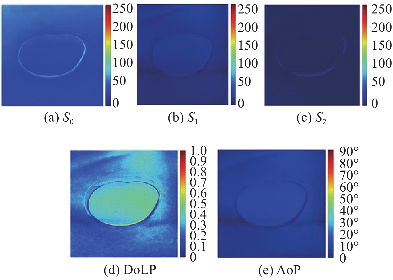
$$AoP = \frac{1}{2}\arctan (\frac{Q}{I})$$ (18) 通过图像配准等处理将获取的4幅水面油膜的偏振图转换为Stokes分量图如图9所示,图9(a)~(c)分别表示
${S_0}$ 、${S_1}$ 和${S_2}$ 分量的灰度图像。参考公式(17)和公式(18),得出水面油膜场景图像的线偏振度图(见图9(d))和偏振角图(见图9(e))。从DoLP图可以看出,油膜的线偏振度在0.5~0.7范围内,而海水的线偏振度在0.2~0.4范围内。AoP图中油膜和海水的角偏振度都在0°~10°范围内。将正常拍摄的油膜场景原图像分别与线偏振度图、偏振角图进行对比评价。分别计算3幅图像的信息熵等5个指标,定量比较3幅图像质量[12]。可见偏振度和偏振角图在成像对比度和海面油膜识别精度方面较有优势。
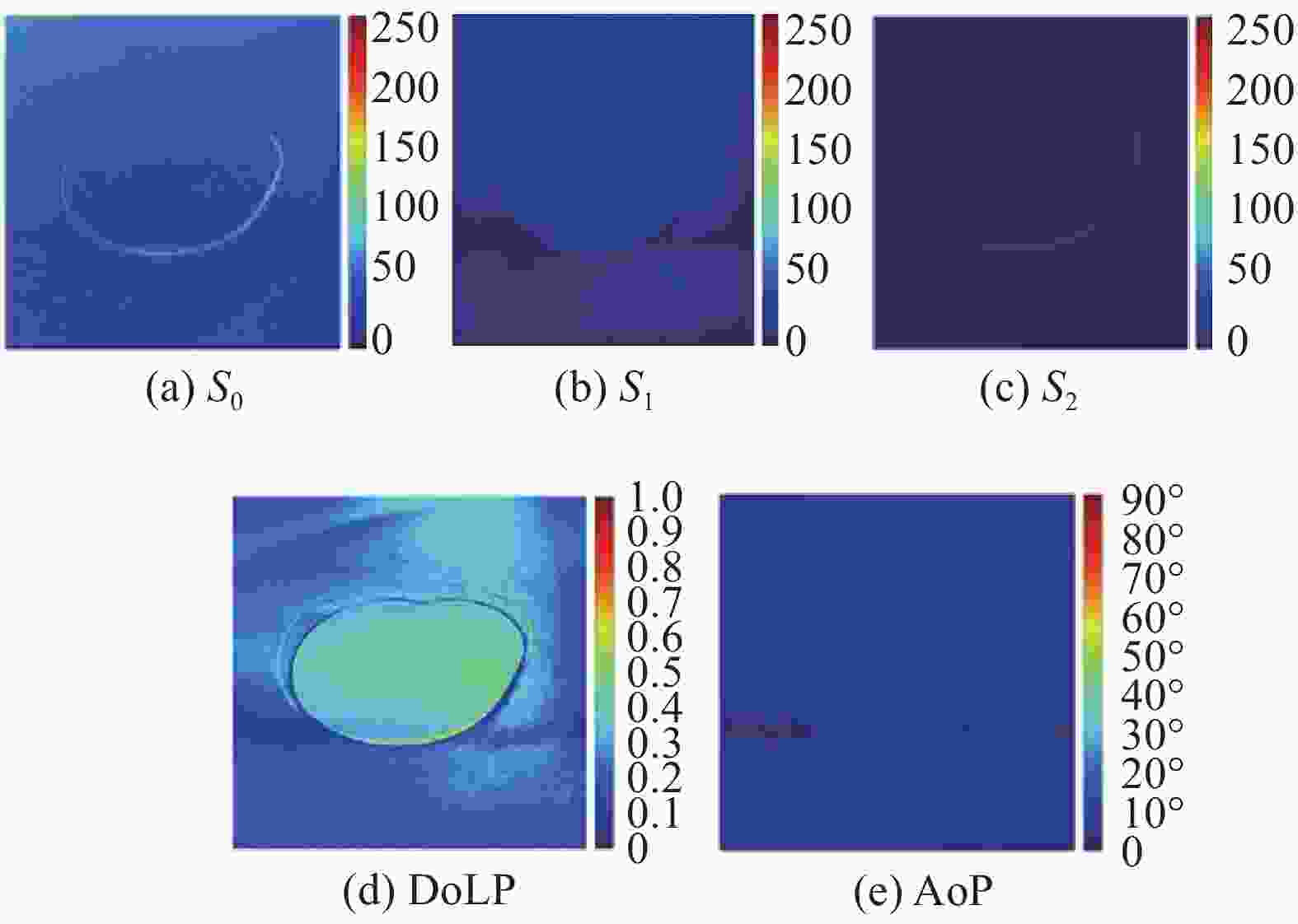
图 9 Stokes分量图以及线偏振度图和偏振角图
Figure 9. Stokes component diagram,the linear polarization degree diagram and polarization angle diagram
表 1 图像质量评价结果
Table 1. Image quality evaluation results
Target Original image Linear polarizaiton diagram Polarization angle diagram Information entropy 5.237 6.579 5.496 Standard deviation 10.146 24.449 11.587 Edge strength 2.341 34.640 16.110 Average gradient 0.212 3.460 1.598 Image definition 0.223 4.418 2.000 -
文中分析了粗糙海面海水和油膜的偏振反射特性,通过建立海面海水和油膜的pBRDF函数,可以得出以下结论:(1)当太阳天顶角到达海水或油膜的布儒斯特角时,
$2\pi $ 空间内P偏振反射率峰值达到最小值,而S偏振反射率随太阳天顶角的增加而增加,两种介质的偏振反射率随太阳入射角度变化的趋势大致相同;(2)随着海面风速的加快,偏振反射率在$2\pi $ 观测空间的有效反射区域逐渐扩大,且偏振反射率峰值显著降低;(3)风向只会造成偏振双向反射率分布函数的空间位置发生旋转,而不影响反射率峰值变化;(4)不同太阳天顶角时,粗糙海面海水和油膜的线偏振度空间分布趋势类似,有些许不同。对于原理性实验结果显示,海水和油膜的线偏振度有明显差别,而偏振角差异不明显;利用偏振探测获取目标场景的偏振度等信息,能够提高海面油膜的识别精度,增强目标场景的边缘强度和清晰度。
Simulation experiment of polarization reflection characteristics of the oil slick
-
摘要: 为了给海面溢油污染识别检测提供理论基础,根据菲涅尔反射公式的偏振反射系数,结合偏振双向反射率因子和粗糙海面的概率密度分布函数,建立了完善的pBRDF模型,仿真在不同太阳入射角度、不同探测器观测角度以及不同海面风速风向等条件下海水和油膜的偏振反射分布函数。结果表明:海水和油膜太阳天顶角为53°和56°时P偏振反射率分别为1.0×10⁻⁵和2.5×10⁻⁵,S偏振反射率随着太阳天顶角的增加而增加;海面风速越大偏振反射率峰值越小;海面风向只改变pBRDF的空间位置;海水和油膜线偏振度空间分布有明显差异。搭建实验平台相机以40°拍摄时,得出海水和油膜的线偏振度分别在0.2~0.4, 0.5~0.7之间,同时表明利用偏振探测获取目标场景的偏振度和偏振角图可提高图像质量。Abstract: To provide a theoretical basis for identification and detection of oil spill pollution on the sea surface, based on the polarization reflection coefficient of Fresnel reflection formula and combined with polarization bidirectional reflectivity factor and probability density distribution function of rough sea surface, a perfect pBRDF model was established. Then the polarization reflection distribution function of sea water and oil film was simulated under different solar incident angles, different detector observation angles and different sea surface wind speed and wind directions. The results show that, firstly, P-polarization reflectance reaches 1.0×10⁻⁵ and 2.5×10⁻⁵ respectively when the solar zenith angle of seawater and oil film is 53° and 56°. S-polarized reflectance increases with the increase of the solar zenith angle. Moreover, the higher sea surface wind speed is, the smaller peak value of polarization reflectance is. Additionally, wind direction only changes spatial position of pBRDF. Finally, the spatial distribution of linear polarization degree between seawater and oil film is obviously different. Experiment platform was set up with the camera working at 40°. The conclusion is obtained that the linear polarization of seawater and oil film is between 0.2−0.4 and 0.5−0.7, respectively. It also shows that using polarization detection to obtain the polarization degree and polarization angle of the target scene can improve the image quality.
-
Key words:
- oil slick /
- pBRDF /
- polarization reflection characteristics
-
图 3 粗糙海面海水偏振双向反射率分布(不同太阳天顶角)
Figure 3. Distribution of bidirectional reflectance of water polarization in rough sea (different solar zenith angles)
图 4 粗糙海面油膜偏振双向反射率分布(不同太阳天顶角)
Figure 4. Bidirectional reflectance distribution of oil film polarization at rough sea surface (different solar zenith angles)
图 5 粗糙海面油膜的S偏振反射率分布(不同风速)
Figure 5. S polarization reflectance distribution of oil film at rough sea surface (different wind speeds)
图 6 粗糙海面油膜的S偏振反射率分布(不同风向)
Figure 6. Distribution of S polarization reflectance of oil film in rough sea surface (different wind direction)
图 7 粗糙海面海水和油膜的线偏振度分布(不同太阳天顶角)
Figure 7. Distribution of linear polarization of seawater and oil film in rough sea (different solar zenith angles)
图 8 偏振成像实验场景图以及采集的4幅海面油膜偏振图像
Figure 8. Polarization imaging experiment scene and four polarization images of oil film on the sea surface were collected
图 9 Stokes分量图以及线偏振度图和偏振角图
Figure 9. Stokes component diagram,the linear polarization degree diagram and polarization angle diagram
表 1 图像质量评价结果
Table 1. Image quality evaluation results
Target Original image Linear polarizaiton diagram Polarization angle diagram Information entropy 5.237 6.579 5.496 Standard deviation 10.146 24.449 11.587 Edge strength 2.341 34.640 16.110 Average gradient 0.212 3.460 1.598 Image definition 0.223 4.418 2.000  下载: 导出CSV
-
[1] Li Yu, Chen Jie, Zhang Yuanzhi. Research progress of synthetic aperture radar sea surface oil spill detection [J]. Acta Electronica Sinica, 2019, 41(3): 248−259. (in Chinese) [2] Li Chengyang, Liu Zhiwen, Liu Kang, et al. Space hyperspectral remote sensing application research progress[J]. Infrared and Laser Engineering, 2019, 48(3): 9-23. (in Chinese) [3] Gao Jun, Bi Ran, Zhao Lujian, et al. Global optimal reconstruction of fog images using polarization information [J]. Optical Precision Engineering, 2017, 25(8): 2212−2220. (in Chinese) doi: 10.3788/OPE.20172508.2212 [4] Li Shujun, Jiang Huilin, Zhu Jingping, et al. Development status and key technologies of polarization imaging detection technology [J]. Chinese Optics, 2013, 6(6): 803−809. (in Chinese) [5] Zhang Weiguo. Polarization detection technology under the background of sea surface solar flare [J]. Chinese Optics, 2018, 11(2): 231−236. (in Chinese) doi: 10.3788/co.20181102.0231 [6] Lv Yunfeng. Polarization characteristics of water bodies[D]. Changchun: Northeast Normal University, 2012. (in Chinese) [7] Zhang Longli, Ma Shinan, Yang Haoran, et al. Relationship between refractive index and combustion heat of crude oil distillate [J]. Laboratory Research and Exploration, 2016, 35(5): 14−17. (in Chinese) doi: 10.3969/j.issn.1006-7167.2016.05.004 [8] Yoshimori K, Itoh K, Ichioka Y. Optical characteristics of a wind-roughened water surface: a two-dimensional theory [J]. Applied Optics, 1995, 34(27): 6236−6247. doi: 10.1364/AO.34.006236 [9] Cox C, Munk W. Measurement of the roughness of the sea surface from photographs of the suns glitter [J]. Journal of the Optical Society of America, 1954, 44(11): 838−850. doi: 10.1364/JOSA.44.000838 [10] Zhang Jiamin, Shi Dongfeng, Huang Jian, et al. Research on full Stokes polarization correlation imaging technology [J]. Infrared and Laser Engineering, 2018, 47(6): 0624001. (in Chinese) [11] Chen Yongtai, Zhang Ran, Lin Wei, et al. Design and construction of real-time all-polarization imaging detector in the sky [J]. Optics Precision Engineering, 2018(4): 816−824. (in Chinese) [12] Zhang Yang. Design of four-camera real-time polarization imaging system[D]. Xi'an: Xi 'an University of Electronic Science and Technology, 2018: 53−54. (in Chinese) -

 点击查看大图

计量
- 文章访问数: 1140
- HTML全文浏览量: 1076
- PDF下载量: 44
- 被引次数: 0


