


-
将吸收光谱技术与CT(Computer Tomography)技术相结合,可以实现对流场的二维分布测量[1-3],但是在实际测量中,发动机尺寸、测量环境等因素,限制了安装测量探头的位置和大小。目前,采用主要分立式探头对发动机流场进行测量。测量探头包含嵌入在发动机的固定底座、光纤聚焦透镜、光束调节装置等,探头尺寸在2~3 cm,因而限制了探头的安装数目和测量的空间分辨能力[4]。美国弗吉尼亚大学Busa等人[5]设计了一种旋转扫描式扇形光生成系统,该系统包含光学探头的“TED-BOX”和基座旋转台,通过TED-BOX底座的旋转实现扇形光的生成,空间分辨率达到2 mm×2 mm,在对NASA超燃直连台测试中,为了实现对测量区域的完全覆盖,测试平台需要重复测量8次实验[6]。北京航空航天大学徐立军等人[7-8]提出了一种由梯形棱镜和柱面棱镜构成的扇形光测量系统,与传统利用旋转台旋转扫描产生扇形光的系统相比具有体积小、稳定型好的优势,为了保证扇形光束的发散角,且可以完全覆盖被测区域,并将其应用到风洞出口处温度和组分浓度的二维分布测量,测量的空间分辨率为0.79 cm2[9]。日本德岛大学的Deguchi等人[10-11]采用平行光束投影的方式,设计了8路的测量环系统用于测量平面火焰炉温度和组分浓度。王珍珍与Deguchi等人[12]合作,利用16路平行光束投影测量了煤粉燃烧器火焰不同时刻温度二维分布。英国曼彻斯特的Wright等人[13-14]设计了一种6个角度,每个角度21条平行光投影的测量装置,对火焰直径约为1.4~1.7 m的航空发动机出口CO2浓度和温度进行测量,测量的空间分辨率为10 cm×10 cm[15]。随后,英国爱丁堡大学McCann小组的Fisher等人[16-17]针对该实验系统开展了数据的快速采集和算法相关研究。中国科学院合肥物质研究院安徽光学精密机械研究所Xia等人[18]通过将测量探头的旋转方式,实现了投影光线间隔为5 mm、2个投影角度的二维测量。航天工程大学的宋俊玲等人[19]设计了移动旋转光学测量系统,可以用于稳态流场的多角度测量。对于发动机瞬态流场分布测量,无法采用移动旋转的方式增加投影光线数目,为了提高测量的空间分辨率,势必发展一种嵌入式、高密度的光学测量探头。
文中提出了一种基于自由曲面透镜和柱透镜阵列的高密度测量环设计方法,采用扇形光束投影并采用双层结构设计,实现了在5 cm×7 cm测量流场区域内,光线间隔为5 mm,88路光线投影,实现了对发动机流场的高密度二维分布测量。
-
利用激光吸收光谱技术对气体参数进行测量时,当激光频率与被测气体分子的共振频率相同时,激光能量被吸收。激光的衰减程度可以表示为:
$$\frac{{{I_t}}}{{{I_0}}} = \exp ( - {\alpha _v}) = \exp \left[ { - PS(T)\phi (v)\chi L} \right]$$ (1) 式中:I0为入射激光强度;It为穿过被测流场后激光强度;α为光谱吸收吸收率信号;P为气体总压;χ为待测气体组分浓度;S(T)为所用谱线ν在温度T时的谱线强度;L为激光束穿过被测流场的长度;ϕ(ν)为线型函数,在整个频域上的积分值为1,公式(1)可以改写为:
$$A = \int_{ - \infty }^\infty {{\alpha _v}{\rm d}v = } P\chi S(T)L$$ (2) 式中:A表示积分吸收面积。
将吸收光谱技术与CT技术相结合,成为激光吸收光谱层析技术(LAT),其基本原理是通过在被测流场截面内布置多条光线,利用每条光线穿过流场不同位置实现携带流场的分布信息,获得的数据为光线沿着光路径的积分结果,再利用重建算法,实现对流场的二维分布测量。其中光线分布设计和光学系统搭建是实验数据获取的关键步骤。
-
在光路设计中,需要考虑发射和接收单元最小尺寸、光线穿过流场最短长度、发射光线最大偏转角度等因素,以最小间隔为5 mm,根据实际被测发动机尺寸,被测区域尺寸为7 cm×5 cm,在矩形区域的四条边上等间隔设计发射端或接收端位置,同时设扇形光转换系统可以将线光转换为扇形光的最大张角为90°,研究发射端位置对测量结果的影响。
设原始模型温度为双高斯分布,范围为500~1300 K,组分浓度为单高斯分布,范围为0.02~0.1,原始模型分布如图1所示。

图 1 原始模型分布
Figure 1. Original models
采用代数迭代算法对原始温度和组分浓度分布进行二维重建,不同光线分布下重建结果如图2所示。其中前4种扇形光线布局的投影光线数目为96条,发射端数目为4个,第5种为平行光投影,光线数目为24条,第6种为仅有1层光线投影时的重建结果。
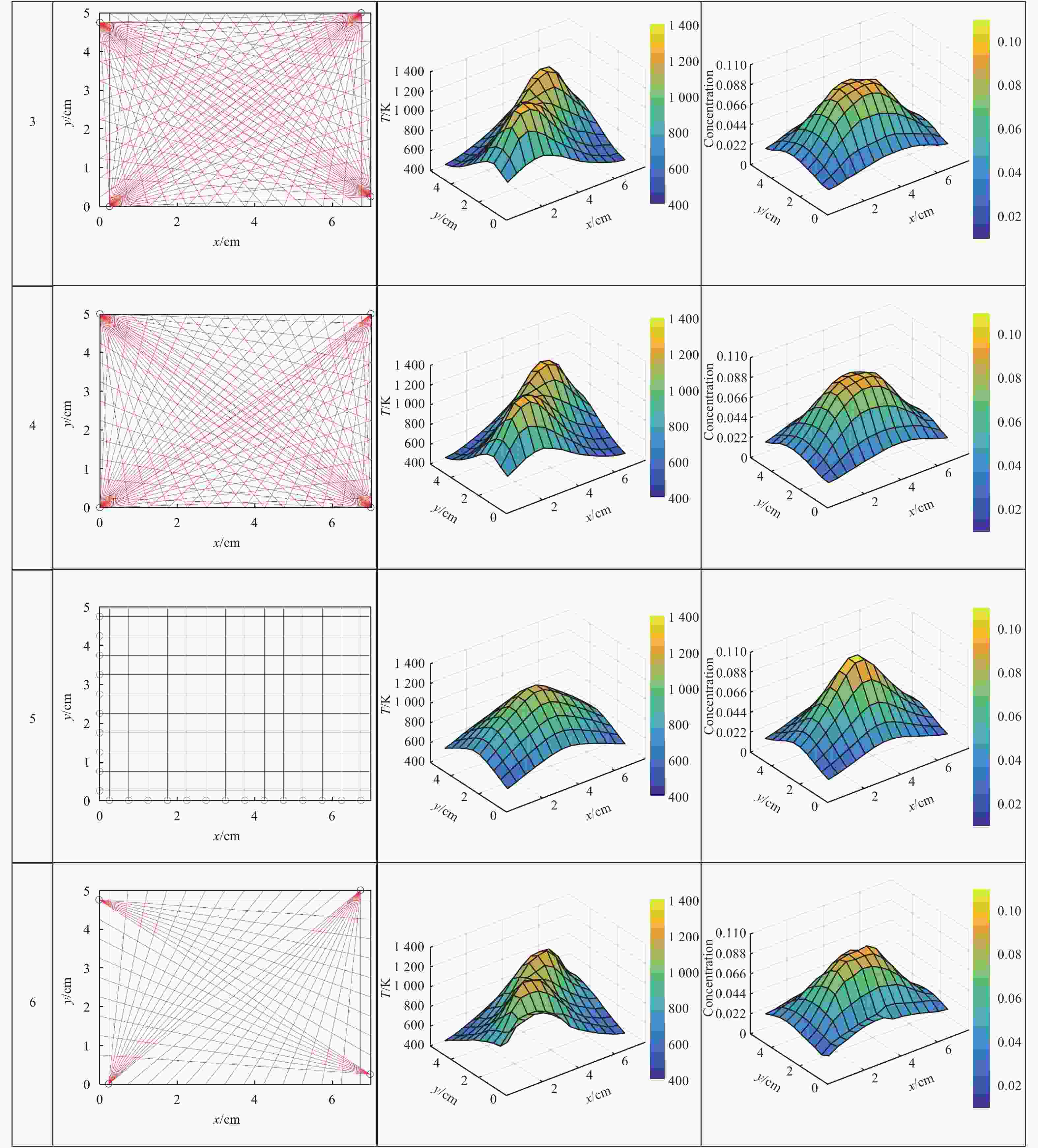
图 2 不同光线分布下的温度和组分浓度重建结果
Figure 2. Temperature and concentration reconstructed results for different line distribution
计算重建结果的归一化平均绝对误差:
$$Er = \frac{{\displaystyle\sum\limits_{m = 1}^M {\displaystyle\sum\limits_{n = 1}^N {\left| {f_{m,n}^{{\rm{rec}}} - f_{m,n}^{{\rm{orig}}}} \right|} } }}{{\displaystyle\sum\limits_{m = 1}^M {\displaystyle\sum\limits_{n = 1}^N {\left| {f_{m,n}^{{\rm{orig}}}} \right|} } }}$$ (3) 式中:fm, n表示被测区域被离散为m × n个网格;f表示网格的温度或者组分浓度。图3为图2对应光线分布的温度和组分浓度的重建误差。从图中可知,发射端的位置越靠近边角区域,重建效果越好,在第4种情况时,发射端位于矩形截面的顶点位置,温度和浓度的重建误差为0.028和0.046,平行光线温度重建误差为0.17。

图 3 6组不同光线分布下的温度和浓度重建误差
Figure 3. Temperature and concentration reconstruction errors for six kinds of line distribution
-
2.1节数值模拟发现端位置的实验中得出发射端位于边角时重建精度最高,然而在实际测量中,由于扇形光束发散角和能量限制无法实现。将一个发射端一分为二,分别放在边角的两边,这样可以使光线最接近于发射端在边角的情况。图4 (a)为发射端位于边角的理想情况,图4 (b)为改进后发射端示意图,近似为发射端在边角的情况。

图 4 发射端的改进示意图
Figure 4. Schematic of transmitter improvement
扇形光的投影需要完备的投影角度,此时需要解决的问题是一个发射端接收两个光线信号的问题。扇形光需要通过偏转镜准直再由聚焦透镜聚焦至光纤端面,而不同的光线的偏转角不同,因此,无法用一个偏转镜实现两个光线的准直。为了解决这一问题,将探头设计为双层结构,层析过程忽略两层间隔,假设两层流场分布相同,一个发射端对应一层的接收探头,这样每个接收端只需接收一条光线,避免了上述问题。图5为双层探头结构示意图。

图 5 双层探头光学结构示意图
Figure 5. Schematic of two layers optical probe
以7 cm×5 cm的流道截面为对象,用上述光学系统设计测量环。采用4个发射端,光线接收端的间隔为5 mm。双层结构的光线布局如图6所示,一层与二层的光线布局呈镜像关系,每层接收端的高度为5 mm,两层之间间隔为4 mm。根据最小光线间隔,长边有14个探头器位置,短边有10个探测器位置,两者都需要匀出一个用于发射端,故面向长边的发射端有13条光线,面向短边的发射端有9条光线,测量环总体可布设88条光线。
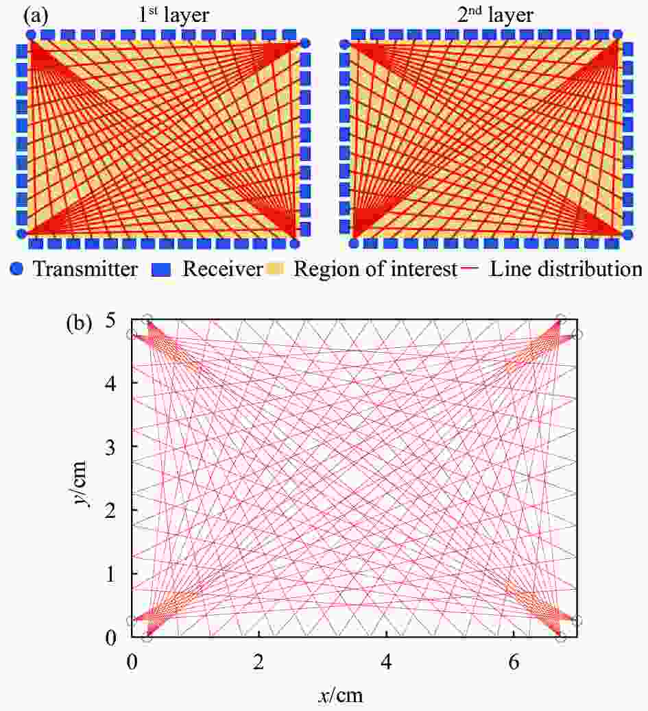
图 6 双层结构光学探测器的光线布局示意图
Figure 6. Line distribution for two layers optical detector
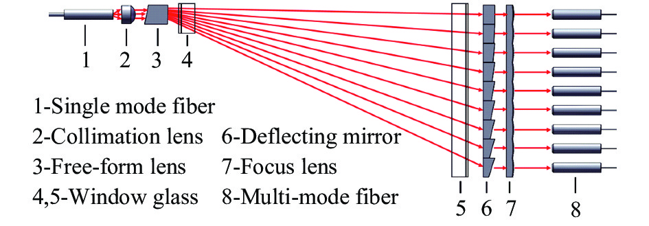
发射端采用面-点的结构形式,利用自由曲面准直设计方法,获得高均匀性矩形线光源。激光从入射光纤(NA=0.14)输出经准直透镜(Thorlabs, 354350-C)准直,由自由曲面透镜转换为扇形光,穿过入第一个窗口玻璃进入流场,穿过第二个窗口玻璃离开流场,由楔形棱镜偏转和聚焦透镜聚焦,进入接收光纤后传送至探测器。收发端结构设计如图7所示。

图 7 扇形光束产生光学系统
Figure 7. Optical system for fan-beam generator
自由曲面特指面型没有具体表达式,由离散点拟合而成的面型。根据扇形光的投射需要设计面型,具体步骤如下:
(1)确定扇形光发射位置与接收位置,设计入射光面与投射像面。入射光的高斯光束强度分布为:
$$A(x) = \int_0^x {P \cdot {{\rm e}^{ - \frac{{2{R^2}}}{{{\omega ^2}}}}} \cdot 2\pi R \cdot {\rm{d}}R} $$ (4) 式中:R为沿着束腰方向往外方向的坐标;ω为高斯光束的束腰;A(x)表示高斯光束在半径为x的圆形以内包含的能量。
投射像面强度分布为:
$$B(t) = EtK$$ (5) 式中:B为高斯光束强度;E为投射像面的光强分布;K为投射目标面的宽度;t为线光源上某一处的位置坐标。
(2)建立入射光面到投射像面的映射关系。令A(x)=B(t),设边界条件为:x趋于无穷大时,t趋近于目标投射面宽度H,可得:
$$t = H\left( {1 - {{\rm e}^{ - \frac{{2{x^2}}}{{{\omega ^2}}}}}} \right)$$ (6) (3)建立自由曲面与入射光面积投射光面之间的映射关系。设入射光矢量为
$\overrightarrow {In} = (0,0,1)$ ,出射光矢量为$\overrightarrow {Out} = (x/h,y/h,{\textit{z}}/h)$ ,其中$h = 1/\sqrt {{x^2} + {y^2} + {{\textit{z}}^2}} $ ,自由曲面的法线矢量为:$$\overrightarrow N = \left(\frac{{\partial f}}{{\partial x}},\frac{{\partial f}}{{\partial y}},\frac{{\partial f}}{{\partial z}}\right)$$ (7) 式中:f为自由曲面方程f (x,y,z),根据折射定律
$\overrightarrow N {\rm{ = }}\overrightarrow {out} - \overrightarrow {in} $ ,建立了自由曲面f与投射像面的映射关系。(4)通过数值方法解算步骤(3)建立的偏微分方程,得出自由曲面f的面型分布。
产生折射的扇形光经偏转镜准直,然后通过聚焦透镜将光束聚焦于接收光纤的端面中心,实现耦合输出。不同位置的光束其角度不同,因此偏转镜的斜面角度也不相同,需要分别计算优化不同位置的偏折镜的斜面角,从而实现最佳的准直效果。聚焦透镜的最小间隔为5 mm,接收端最小间隔为5 mm。测量区域为50 mm×70 mm,其中短边的接收端为9个,长边的接收端为13个,两层结构中共有接收光线88路。线光源实际光斑测量结果照片如图8所示。

图 8 线光源产生光斑照片
Figure 8. Photograph of the actual spots from the linear light
实验中采用功率计对整个光学系统进行传输效率测试,测试结果如表1所示。实验首先对每路接收端光纤入射光强进行测试,当入射光强为12 mW时,分别记录8个发射端对应的接收端的光强,然后将激光接入到发射端,记录同一发射端对应不同接收端的光强,根据测量结果计算整个光学系统的能量利用效率和光强均匀性。表中发射端编号1~4为下层光线测试结果,发射端编号5~8为上层发射端光线测试结果。能量利用效率η计算公式为:
表 1 光学系统功率测试结果
Table 1. Power measurement results of optical system
(a) Long edge test results/mW Transmitter number 1 3 5 7 Input power: P 11.7 13 13 12.8 Output power: qi 1 0.36 0.58 0.37 0.35 2 0.56 0.57 0.67 0.45 3 0.44 0.56 0.6 0.57 4 0.51 0.55 0.54 0.59 5 0.54 0.55 0.57 0.6 6 0.37 0.56 0.63 0.57 7 0.57 0.57 0.61 0.62 8 0.56 0.53 0.64 0.57 9 0.45 0.54 0.48 0.5 10 0.53 0.43 0.62 0.58 11 0.57 0.58 0.61 0.59 12 0.65 0.52 0.63 0.62 13 0.36 0.32 0.41 0.44 Total output power: Q 6.47 6.86 7.38 7.05 Energy efficiency: $\eta $ 55.30% 52.77% 56.77% 55.08% Receiver uniformity: θ 55.38% 55.17% 55.22% 56.45% $$\eta = \frac{Q}{P} = \frac{{\displaystyle\sum\nolimits_{i = 1}^n {{q_i}} }}{P}$$ (8) 式中:P为入射激光总能量,为图7中进入入射光纤前测量的激光能量值;Q为接收端能量和,为图7中在接收光纤处测量结果总和。接收端均匀性θ计算公式为:
$$\theta = \frac{{{q_{\min }}}}{{{q_{\max }}}}$$ (9) 即同一发射端发出的光线最小值与最大值的比。
由表1测量结果可知,整个光学系统的光线利用效率大于50%,光强均匀性为大于55%。由于长边接收端数目较多,所以每个接收端的功率低于短边的功率。
(b) Short edge test results/mW Transmitter number 2 4 6 8 Input power: P 11.8 12 12.9 11.68 Output power: qi 1 0.63 0.69 0.68 0.55 2 0.52 0.62 0.58 0.65 3 0.7 0.7 0.58 0.52 4 0.67 0.71 0.65 0.64 5 0.79 0.8 0.64 0.92 6 0.82 0.8 1.04 0.88 7 0.72 0.82 1.05 0.9 8 0.93 0.83 1.03 0.93 9 0.61 0.46 0.59 0.53 Total output power: Q 6.39 6.43 6.84 6.52 Energy efficiency: $\eta $ 54.15% 53.58% 53.02% 55.82% Receiver uniformity:θ 55.91% 55.42% 55.24% 55.91% -
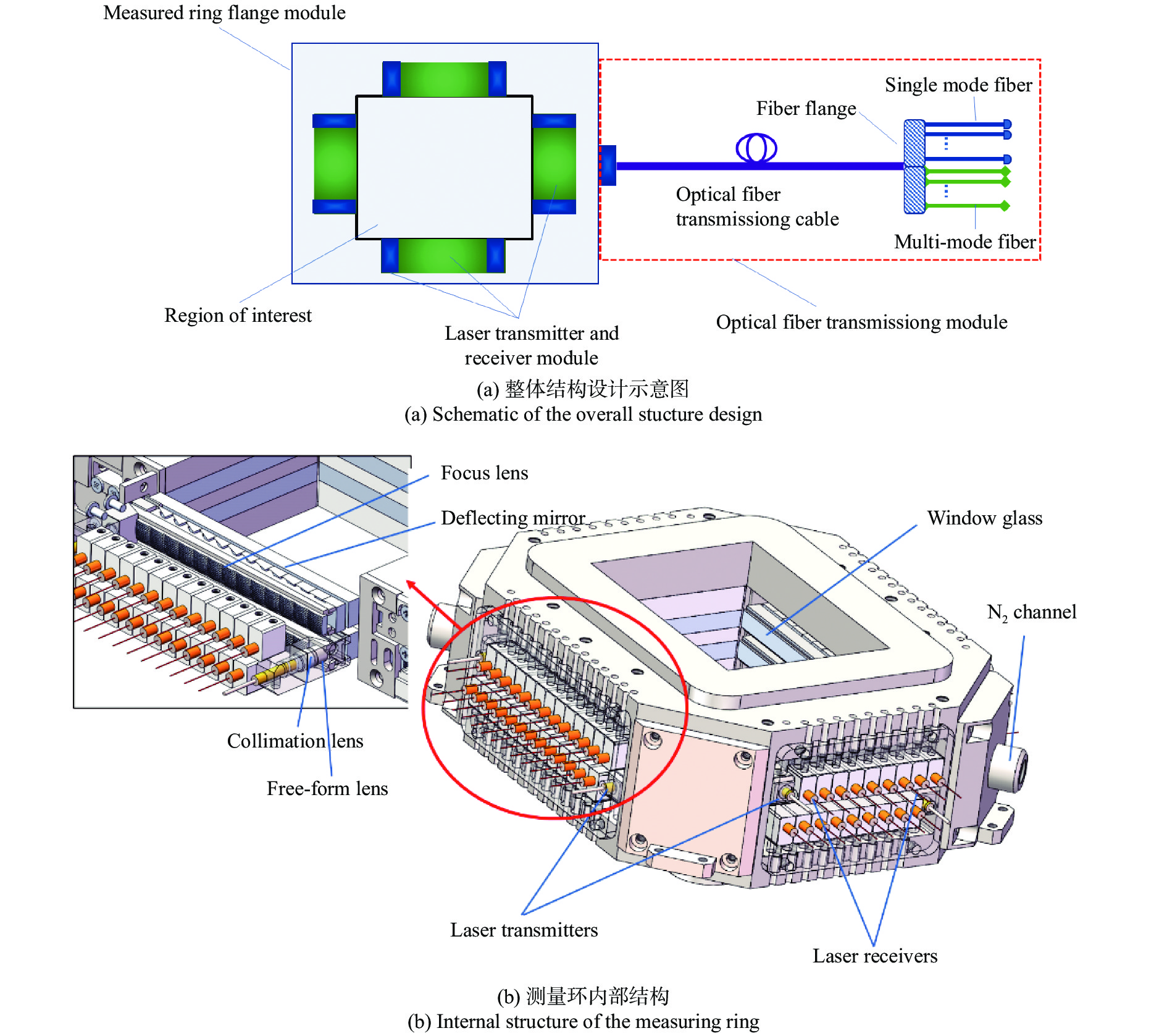
为了实现对超燃冲压发动机燃烧场参数的二维测量,在光学系统设计的基础上,增加了与发动机接口、光信号传输模块的设计。测量环包含激光发射接收模块、光纤传输模块、测量环法兰模块三部分组成,如图9所示。

图 9 测量环系统组成
Figure 9. Measuring ring system composition
激光器发出的激光经单模光纤传输至激光发射单元,激光发射单元将点光源转换为扇形光束,扇形光束穿过被测流场后被激光接收单元接收;激光接收单元将接收到的激光会聚传输到多模光纤内;根据第2节研究结果,激光发射接收模块为二层矩形结构,每层结构有4个激光发射单元,每个激光发射单元位于矩形每条边的一侧,另外一层的激光发射单元位于相反一侧;每个激光接收单元的间隔为5 mm,可以实现最小的空间分辨率为5 mm×5 mm气体参数二维重建测量。
光纤传输模块包括多条多模光纤、多条单模光纤、光纤合束法兰、光纤传输线缆组成;测量环法兰内部的光纤均为带有外包层,所有光纤汇总后封装进入铠缆封装的光纤传输线缆中;光纤合束法兰采用8合1的耦合方式,将8根400 μm芯径的多模光纤耦合进入一根800 μm芯径的多模光纤;光纤合束法兰的尾部为多根800 μm芯径的多模光纤和8根单模光纤,多模光纤采用SMA接口,单模光纤采用FC/APC接口。
测量环法兰模块包括顶端吊环、测量环法兰腔体、氮气通道、测量环密封盖、固定底座;测量环法兰外部具有定位槽,与发动机燃烧室出口处相连接;测量环法兰内部掏空用于安装激光发射接收模块,避免因挤压和振动引起光学原件的变形;测量环密封盖是用于对测量环法兰内部进行密封处理,测量环密封盖与测量环法兰内部之间有0.5 mm的间隙作为缓冲区域;测量环法兰底面、顶面和周边均填充隔热石棉,减少发动机燃烧产生热量对光学器件的影响;测量环法兰内部还留有氮气通道入口和出口,用于减少外部环境气体对测量结果的影响。
-
文中设计了一种基于自由曲面透镜和柱透镜阵列相结合的高密度光学测量环,用于超燃冲压发动机流场内流场气体温度和组分浓度二维分布测量。通过数值仿真的方式研究了发射端位置对重建结果的影响,同时比较了相同光线间隔时平行光束与扇形光束的重建结果。研究结果表明,当发射端位于测量截面边角处,重建误差最小;相同光线间隔时,扇形光束的重建结果优于平行光束重建结果;根据数值仿真结果,设计了扇形光束投影的燃烧场高密度光学测量环,可以实现接收单元最小间隔为5 mm,光线利用效率大于50%,光线总传输效率大于55%。
Design of a high-resolution optical measuring ring for supersonic combustion flow field
-
摘要: 超燃冲压发动机激光吸收光谱测量系统目前主要采用分立式光学探头形式与发动机机体固定,但是受到探头尺寸的限制,无法获得高分辨率的流场信息。文中设计了一种基于自由曲面透镜和透镜阵列相结合的燃烧场高密度光学测量环。该测量环采用两层结构,发射端分别位于每条边最边缘位置,激光准直透镜和自由曲面透镜形成扇形光束,扇形光束穿过被测流场后,经过楔形镜偏转和聚焦透镜聚焦,进入接收光纤后传送至探测器。测量环接收单元最小间隔为5 mm,实现了在5 cm×7 cm空间内88条光线的密集排列。重点讨论光学系统光线分布设计方案,并给出收发端结构设计方案,实验结果表明,光线利用效率大于50%,光线总传输效率大于55%。设计的高密度光学测量环可以直接与发动机机体相衔接,避免环境因素干扰,可以实现对超燃冲压发动机隔离段、燃烧室出口等处温度、组分浓度的二维分布测量。Abstract: The separate optical probes have been widely used in scramjet laser absorption spectroscopy measured system. High resolution flow field cannot be obtained because of the limitation of the probe size. A high-resolution optical measuring ring based on free-curved lens and cylindrical lens was designed for combustion flow field. The beam distribution was determined by numerical simulation. The measuring ring adopted double-layer structure, the transmitters were located at the most edge of each edge. The fan-beam was formed by collimating lens and free-form lens. And then after passing the measuring flow field, the laser beam was defected by the wedge lens and focused by the focusing lens. The measuring ring receiving unit minimum interval was 5 mm, achieved dense array of 88 beams in 5 cm×7 cm space. The beam distribution of the optical system was discussed. The structural design scheme suitable for engine measurement was given. The measurement result shows that the light efficiency is greater than 50%, the total transmission efficiency is greater than 55%. The high-resolution optical measuring ring can be directly connected with the engine body to avoid the interference of environmental factors. The two-dimensional distribution of temperature and concentration in the isolation and outlet of the combustion can be measured.
-
图 2 不同光线分布下的温度和组分浓度重建结果
Figure 2. Temperature and concentration reconstructed results for different line distribution
图 3 6组不同光线分布下的温度和浓度重建误差
Figure 3. Temperature and concentration reconstruction errors for six kinds of line distribution
表 1 光学系统功率测试结果
Table 1. Power measurement results of optical system
(a) Long edge test results/mW Transmitter number 1 3 5 7 Input power: P 11.7 13 13 12.8 Output power: qi 1 0.36 0.58 0.37 0.35 2 0.56 0.57 0.67 0.45 3 0.44 0.56 0.6 0.57 4 0.51 0.55 0.54 0.59 5 0.54 0.55 0.57 0.6 6 0.37 0.56 0.63 0.57 7 0.57 0.57 0.61 0.62 8 0.56 0.53 0.64 0.57 9 0.45 0.54 0.48 0.5 10 0.53 0.43 0.62 0.58 11 0.57 0.58 0.61 0.59 12 0.65 0.52 0.63 0.62 13 0.36 0.32 0.41 0.44 Total output power: Q 6.47 6.86 7.38 7.05 Energy efficiency: $\eta $ 55.30% 52.77% 56.77% 55.08% Receiver uniformity: θ 55.38% 55.17% 55.22% 56.45%  下载: 导出CSV
(b) Short edge test results/mW Transmitter number 2 4 6 8 Input power: P 11.8 12 12.9 11.68 Output power: qi 1 0.63 0.69 0.68 0.55 2 0.52 0.62 0.58 0.65 3 0.7 0.7 0.58 0.52 4 0.67 0.71 0.65 0.64 5 0.79 0.8 0.64 0.92 6 0.82 0.8 1.04 0.88 7 0.72 0.82 1.05 0.9 8 0.93 0.83 1.03 0.93 9 0.61 0.46 0.59 0.53 Total output power: Q 6.39 6.43 6.84 6.52 Energy efficiency: $\eta $ 54.15% 53.58% 53.02% 55.82% Receiver uniformity:θ 55.91% 55.42% 55.24% 55.91%
下载: 导出CSV
-
[1] Wang Z, Fu P, Chao X. Laser absorption sensing systems: Challenges, modeling, and design optimization [J]. Applied Sciences, 2019, 9(13): 2723. doi: 10.3390/app9132723 [2] Hong Yanji, Song Junling, Rao Wei, et al. Progress on tunable diode laser absorption tomography technique for combustion diagnostics [J]. Journal of Experiments in Fluid Mechanics, 2018, 32(1): 43-54. (in Chinese) doi: 10.11729/syltlx20160177 [3] Liu C, Xu L. Laser absorption spectroscopy for combustion diagnosis in reactive flows: A review [J]. Applied Spectroscopy Reviews, 2019, 54(1): 1520-1569. doi: 10.1080/05704928.2018.1448854 [4] Ma L, Li X, Sanders St, et al. 50-kHz-rate 2D imaging of temperature and H2O concentration at the exhaust plane of a J85 engine using hyperspectral tomography [J]. Optics Express, 2013, 21(1): 1152-1162. doi: 10.1364/OE.21.001152 [5] Busa K M, Rice B E, McDaniel J C, et al. Scramjet combustion efficiency measurement via tomographic absorption spectroscopy and particle image velocimetry [J]. AIAA Journal, 2016, 54(8): 2463-2471. doi: 10.2514/1.J054662 [6] Busa K M, Ellison E N, McGovern B J, et al. Measurements on NASA langley durable combustor rig by TDLAT: Preliminary results[C]//51st AIAA Aerospace Sciences Meeting including the New Horizons Forum and Aerospace Exposition 2013, 2013: 1-13. [7] Xu L, Liu C, Jing W, et al. Tunable diode laser absorption spectroscopy-based tomography system for on-line monitoring of two-dimensional distributions of temperature and H2O mole fraction [J]. Review of Scientific Instruments, 2016, 87(1): 013101. doi: 10.1063/1.4939052 [8] Liu C, Xu L, Li F, et al. Resolution-doubled one-dimensional wavelength modulation spectroscopy tomography for flame flatness validation of a flat-flame burner [J]. Applied Physics B, 2015, 120(3): 407-416. doi: 10.1007/s00340-015-6150-9 [9] Zhao W, Xu L, Huang A, et al. A WMS based TDLAS tomographic system for distribution retrievals of both gas concentration and temperature in dynamic flames [J]. IEEE Sensors Journal, 2020, 20(8): 4179-4188. doi: 10.1109/JSEN.2019.2962736 [10] Deguchi Y, Daisuke Y, Akira A. Development of 2D temperature and concentration measurement method using tunable diode laser absorption spectroscopy [J]. Journal of Mechanics Engineering and Automation, 2012, 2(9): 543-549. [11] Choi D W, Jeon M G, Cho G R, et al. Performance improvements in temperature reconstructions of 2-D tunable diode laser absorption spectroscopy (TDLAS) [J]. Journal of Thermal Science, 2016, 25(1): 84-89. doi: 10.1007/s11630-016-0837-z [12] Wang Z, Kamimoto T, Deguchi Y, et al. Two dimensional temperature measurement characteristics in pulverized coal combustion field by computed tomography-tunable diode laser absorption spectroscopy [J]. Applied Thermal Engineering, 2020, 171: 115066. doi: 10.1016/j.applthermaleng.2020.115066 [13] Wright P, Ozanyan K B, Carey S J, et al. Design of high-performance photodiode receivers for optical tomography [J]. IEEE Sensors Journal, 2005, 5(2): 281-288. doi: 10.1109/JSEN.2004.841869 [14] Wright P, McCormick D, Ozanyan K, et al. Progress towards non-intrusive optical measurement of gas turbine exhaust species distributions[C]//2015 IEEE Aerospace Conference, 2015: 1-14. [15] Fisher E M D, Tsekenis S A, Yang Y, et al. A custom, high-channel count data acquisition system for chemical species tomography of aero-jet engine exhaust plumes [J]. IEEE Transactions on Instrumentation and Measurement, 2020, 69(2): 549-558. doi: 10.1109/TIM.2019.2895932 [16] Fisher E, Tsekenis S, Yang Y, et al. An embedded processing design for 192-channel 10-40 MS/s aero-engine optical tomography: Progress and continued DAQ characterization[C]//2018 IEEE International Instrumentation and Measurement Technology Conference (I2MTC), 2018: 1-6. [17] Polydorides N, Tsekenis A, Fisher E, et al. Constrained models for optical absorption tomography [J]. Applied Optics, 2018, 57(7): B1-B9. doi: 10.1364/AO.57.0000B1 [18] Xia H, Kan R, Xu Z, et al. Two-step tomographic reconstructions of temperature and species concentration in a flame based on laser absorption measurements with a rotation platform [J]. Optics and Lasers in Engineering, 2017, 90: 10-18. doi: 10.1016/j.optlaseng.2016.09.005 [19] Song J, Hong Y, Xin M, et al. Tomography system for measurement of gas properties in combustion flow field [J]. Chinese Journal of Aeronautics, 2017, 30(5): 1697-1707. doi: 10.1016/j.cja.2017.08.004 -

 点击查看大图

图(9) / 表(2)
计量
- 文章访问数: 347
- HTML全文浏览量: 105
- PDF下载量: 32
- 被引次数: 0


