


-
随着太赫兹(Terahertz, THz)技术的发展,其应用领域不断拓展,在射电天文、频谱探测、生物学、医学成像、高速通信以及军事雷达等方面有很大的应用潜力。140 GHz、220 GHz以及340 GHz是THz频段内的一个“大气窗口”频率,在雷达、军事通信,以及人体安检等方面有着重要的应用价值[1-4]。基于当前射频探测技术及成本,人体安检领域的THz应用,还是以300 GHz频率以下为主[5]。国外研究机构对太赫兹混频器的研究起步较早,在1978年,Eeicr R. Carlson等基于悬置微带线的117 GHz的二次谐波混频器研究,获得变频损耗(Conversion Loss, Con-Loss)为6.5 dB[6],参考文献[7]阐述了183 GHz的二次谐波混频器,其双边带Con-Loss为6.85 dB,对应混频器噪声温度Tmixer为988 K。而国内则对太赫兹研究起步则较晚,在参考文献[8]中阐述了W波段80~100 GHz二次谐波混频器,谐波混频器的Con-Loss为9.2~12 dB,并且所需要的本振功率仅为6 dBm。参考文献[9]介绍了380 GHz谐波混频器,最佳Con-Loss为9 dB,等效噪声温度Tmixer为2 000 K。但是,这些单通道混频器模块有个共同的特点,即射频(Radio Frequency, RF)输入端、本振(Local Oscillator, LO)输入端和中频(Intermediate Frequency, IF)输出端都在统一个平面,很难在平面进行多通道混频器集成,且不利于系统的性能一致性及质量控制。为降低腔体机械加工难度和成本,保证混频器工作性能,基于当前E面探针过渡结构,文中设计了一种220 GHz四通道混频器集成模块。
-
该混频器集成模块中,IF输出微带线由原来的平行引出,改为垂直引出,金丝绑定线从微带线跳至玻璃绝缘子的同轴针顶端,再优化金属腔体的阻抗匹配,完成IF信号的90°调整,从而有效缩短混频器单通道的横向尺寸,提高通道的横向集成度。为进一步提高系统模型的准确性,基于Silvaco TCAD半导体器件仿真软件对砷化镓(Gallium Arsenide, GaAs)基肖特基势垒二极管(Schottky Barrier Diode, SBD)进行建模计算,依据提取的关键特性参数,结合波导宽带匹配法和紧凑型滤波器,进行混频器模块的高频仿真设计、加工与测试。最后,对混频器模块的IF信号进行低噪声放大与检波,评估该谐波混频器的接收机系统噪声温度Tsys和噪声等效温差(Noise Equivalent Temperature Difference, NETD)。集成混频器模块的四个通道结构一致,在混频器设计时仅对单通道特性进行仿真优化即可。该220 GHz二次谐波混频器腔体结构采用E面对称剖分结构,混频器LO和RF输入端口分别采用标准波导WR8.0和WR4.3,IF输出端子采用玻璃绝缘子和SMA的组合式连接器。信号通过微带LO探针和RF探针实现由矩形波导TE10模式到石英微带电路准TEM模式之间的转变。设计中石英基片厚度为50 µm,宽度为360 µm,相对介电常数为3.78。在微带线中采用紧凑型强谐振Hammer-Head滤波器[10],以充分抑制RF信号和LO信号,同时缩短信号的传输距离;此外,LO输入端口采用减高波导处理,实现LO信号的宽带阻抗匹配。
-
SBD是太赫兹固态器件中最核心的非线性器件。文中采用SBD等效三维器件结构如图1(a)所示。由于反向并联的SBD结构对称,在微波电路和通信系统仿真软件(Advanced Design System, ADS)的Spice模型中只需确认单个SBD的静电学参数即可。SBD的特性参数一般基于微带线高频激励信号去嵌测试方式推导而出,所以测试微带线自身精度,以及其键合形貌都会影响SBD的静电学参数。为进一步提高系统模型的准确性,基于Silvaco TCAD半导体器件仿真软件,构建单个SBD管结结构,如图1(b)所示。基于GaAs基底,设定SBD的功函数为4.87 eV,外延层厚度为0.1 μm,掺杂浓度为2×10¹⁷/cm3;缓冲层厚度为0.7 μm,掺杂浓度为5×10¹⁸/cm3。肖特基接触为圆柱形结构。SBD阴极电极穿过外延层结构,与底部重掺杂的缓冲层接触,形成欧姆接触;而阳极金属圆柱直接与外延层接触,形成肖特基接触。由于GaAs基片主要采用分子束外延法生长,所以外延层与缓冲层为突变结。基于该器件结构,进行静电仿真计算,结果如图2所示,通过计算提取确定SBD的零偏结电容值为0.83 fF,串联电阻为14.7 Ω[11]。在计算肖特基结电容时,可只考虑肖特基结空间电荷区的结电容,金属空气桥结构的寄生效应可通过高频结构仿真软件(High Frequency Structure Simulator, HFSS)对SBD在微带线结构上的三维电磁仿真计算获得的S传输函数来确定。
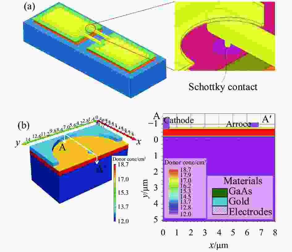
图 1 (a) GaAs SBD在HFSS中的三维模型;(b) GaAs SBD在Silvaco TCAD中的三维模型及外延层掺杂分布情况
Figure 1. (a) 3D-modal of GaAs SBD in HFSS software; (b) 3D-modal of GaAs SBD in Silvaco TCAD and the net doping for the epitaxial layer

图 2 基于Silvaco TCAD计算的肖特基接触C-V特性曲线(a)和接触I-V特性曲线(b)
Figure 2. Schottky contact C-V characteristic curve (a) and I-V characteristic curve (b) calculated based on Silvaco TCAD
-
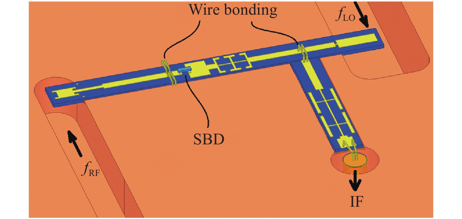
混频器模块仿真设计采用HFSS和ADS结合计算。由HFSS得到混频器无源结构S参数,导入ADS进行电路优化设计。优化过程中主要是针对混频器LO与RF端口的匹配网络结构进行调节,利用波导探针结构实现宽带匹配。此次谐波混频器中的LO滤波器和RF滤波器均采用高抑制Hammer- Head滤波器结构来分别实现LO信号和RF信号的传输。射频信号fRF和的本振信号fLO通过反向并联SBD,混频后总电流只包括本振信号的偶次谐波分量与射频信号的组合项,然后再通过滤波电路选取出差频︱fRF-2fLO︱,形成频率fIF的中频(IF)信号输出。本振滤波器的作用是防止射频信号进入本振端口;中频滤波器的作用是防止本振信号泄漏到中频端口。为保证由二极管对不平衡产生的直流电流接地,混频器的直流接地线采用从射频输入微带线的两旁引出,采用金丝跳线与金属腔侧壁连通。图3给出了220 GHz混频电路基于E面平均剖开腔体的结构。微带线结构固定在LO和RF的E面波导腔中。通过金丝跳线将微带线上的差频信号传输到垂直放置的微带线基板上,然后再通过金丝跳线将滤波后的IF信号传输到玻璃绝缘子的针尖一端并向下传输。
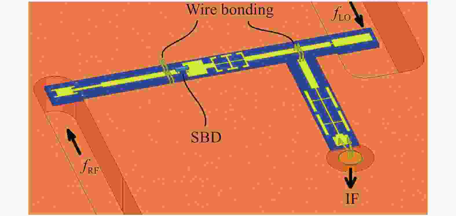
图 3 二次谐波混频器的电路拓扑结构
Figure 3. Circuit topology of the sub-harmonic mixer
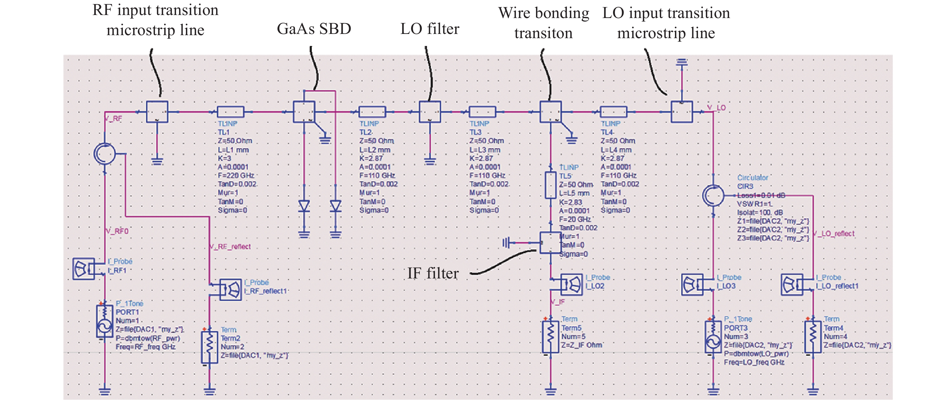
谐波混频电路整体仿真中首先用HFSS对滤波器件进行单独仿真优化,然后对RF和LO端的减高波导和RF、LO波导-微带过渡结构进行结构优化,实现所需频段的性能,结合IF垂直过渡结构,将各部分数据导出S参数包,再将这些参数包代入ADS,通过微带传输线结构,进行匹配优化,达到较优的Con-Loss及本振功率需求。二次谐波混频器的整体仿真模型如图4所示。
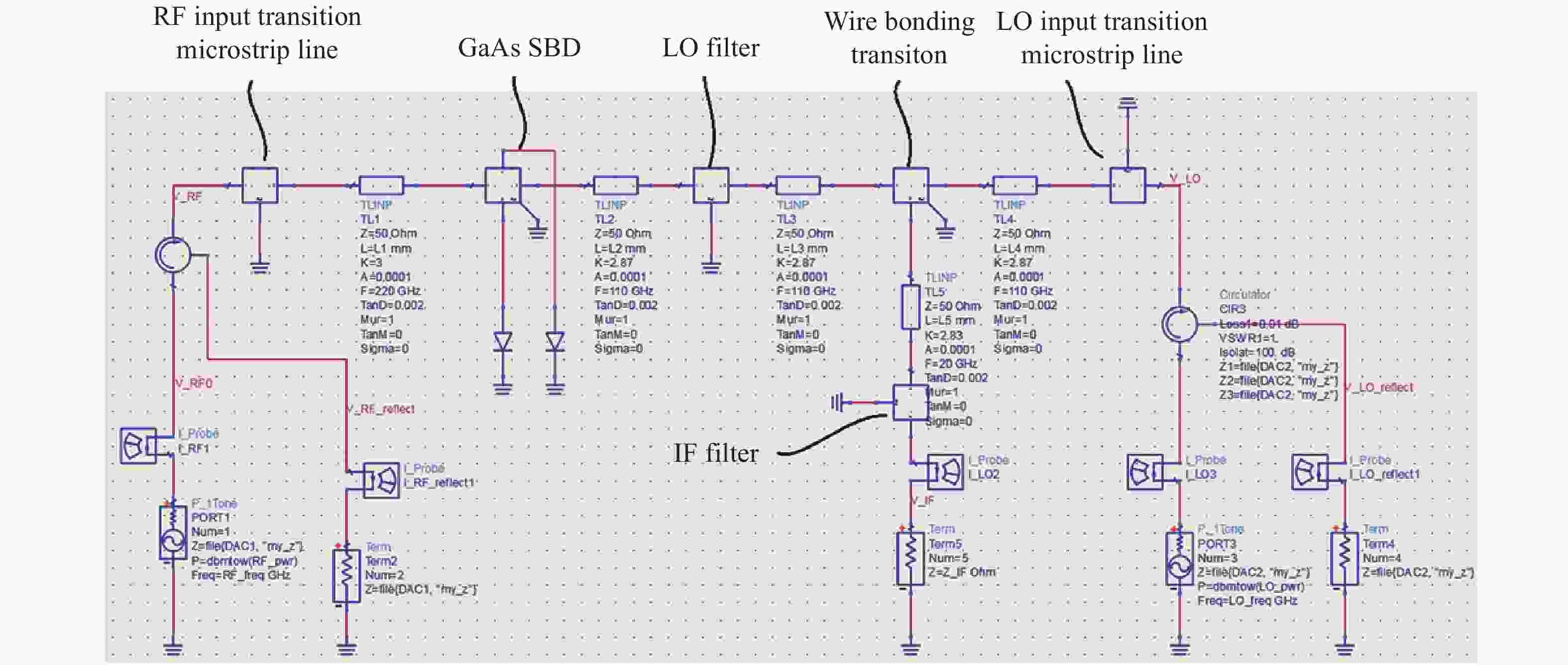
图 4 混频电路的整体仿真模型
Figure 4. Whole simulation model of mixer circuit
-
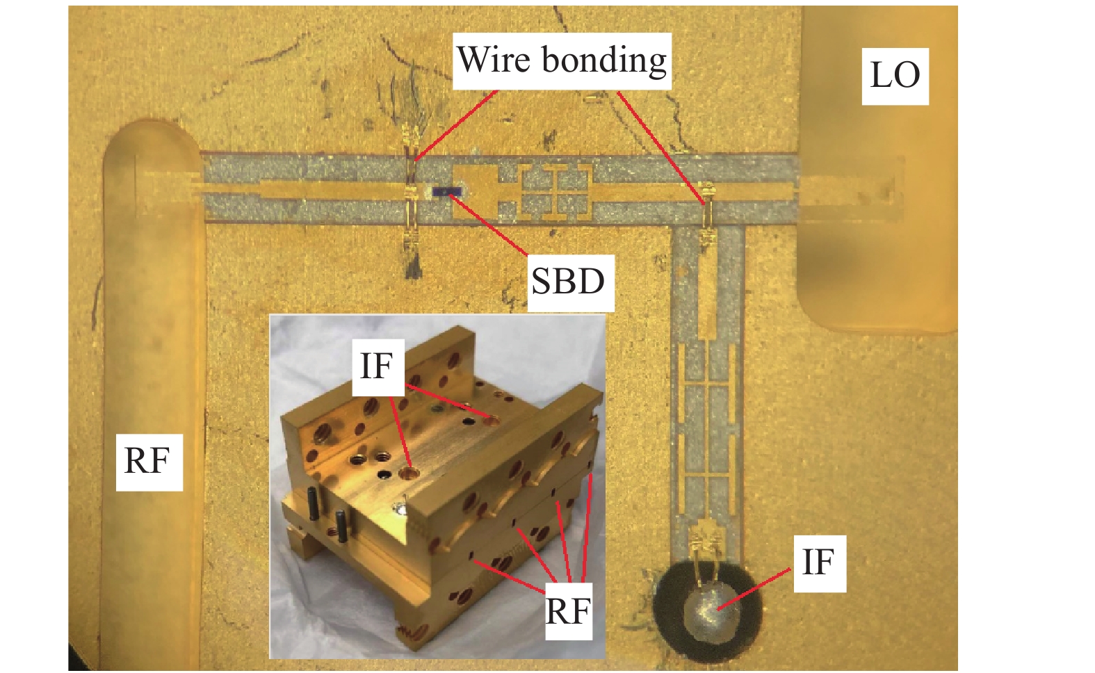
图5为220 GHz二次谐波混频器集成模块的实物图,以及内部石英微带线与SBD的装配情况。由实物照片可见,内部微带线底部采用导电银胶粘贴至沟槽底部且居中;共有三处金丝跳线,由于人工装配,部分金丝跳线存在明显角度和位置偏差。测试表明金丝跳线至玻璃绝缘子针尖部分牢固性一般,用少许导电胶来对该键合部分固化,以提高可靠性。但导电银胶形貌的不可控,会影响模块整体的传输函数。此外,金属腔体的加工精度、导电银胶涂抹均匀性,ADS中采用非SBD模型,以及SBD实际器件结构与模型结构的差异等因素,都会最终影响混频器的变频特性及噪声特性。从四通道模块整体结构可见,四通道的通道间距减小至7 mm,极大的缩短了接收机通道间的间距,其中两个IF输出端从模块的顶端引出,另外两个IF输出端从模块的底部引出(照片中没有显示),且模块可以线性无死区拼接,提高了线阵扫描系统的集成度。

图 5 220 GHz二次谐波混频器集成模块单通道实物图
Figure 5. Single channel image of 220 GHz sub-harmonic mixer integrated module
混频器的变频特性测试时,LO信号频率fLO设定为110 GHz。通过观察LO输入功率与Con-Loss的关系,发现本振功率PLO=7 dBm (5 mW)时,Con-Loss较低且稳定。对射频输入信号200~240 GHz的输入功率进行标定,固定LO输入信号频率fLO和功率PLO后,测试获得射频输入频率与单边带(Single Side Band, SSB)Con-Loss间的关系,测试结果如图6所示,这里给出了模块中三个通道的测试情况。测试结果表明:在本振频率fLO=110 GHz时,fRF在200~240 GHz的SSB Con-Loss为8.6~13 dB;在204~238 GHz的SSB Con-Loss为8.6~11.3 dB,该混频器IF在16~20 GHz时会急剧恶化,这是IF滤波器特性和前后阻抗匹配问题所导致的。此外,对频率点fLO和工作功率PLO进行了调整,fLO=108 GHz,PLO=3 dBm (2 mW)时,fRF在200~236 GHz的SSB Con-Loss为8.4~12 dB;在200~234 GHz的SSB Con-Loss为8.4~11 dB。测试结果与国内其他太赫兹混频器性能比较结果如表1所示,可见文中设计的二次谐波混频器的SSB Con-Loss性能较好,且在LO功率PLO为2 mW即可满足混频器工作,降低了集成系统对本振源的要求。
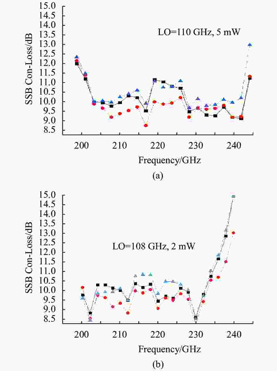
图 6 混频器在(a) fLO=110 GHz,PLO=7 dBm和(b) fLO=108 GHz,PLO=3 dBm条件下的SSB Con-Loss测试结果
Figure 6. Measured results of SSB Con-Loss for mixer under (a) fLO=110 GHz @PLO=7 dBm and (b) fLO=108 GHz @PLO=3 dBm
表 1 太赫兹混频器性能对比
Table 1. Performance comparison of terahertz mixers
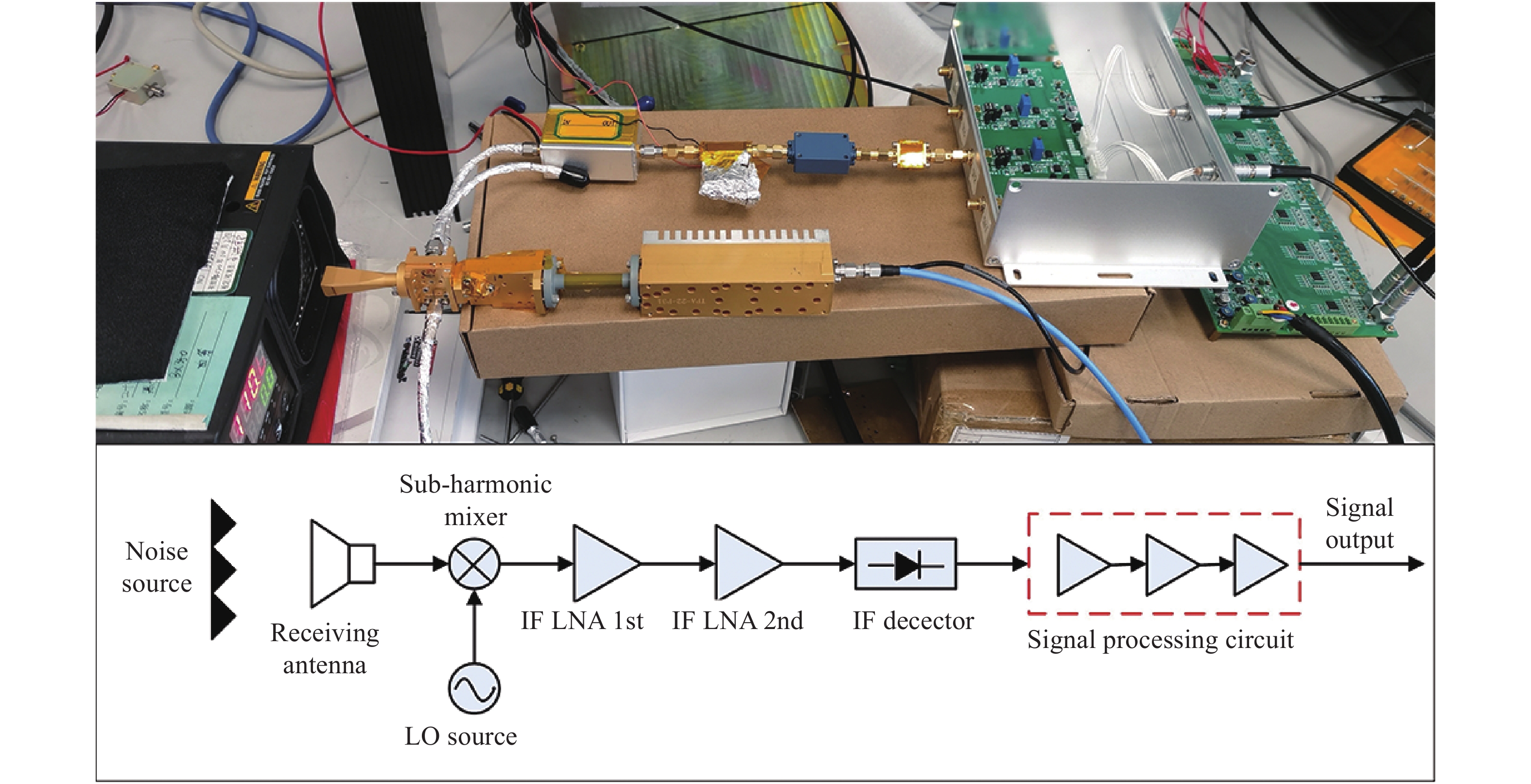
基于该混频器集成模块,搭建220 GHz被动式接收机系统,对该接收机系统的噪声温度Tsys和NETD进行测量。该系统的前端中包括了WR4.3标准波导口太赫兹天线、220 GHz分谐波混频器集成模块、110 GHz三倍频器模块及Ka波段功率放大器模块。由信号源给Ka波段功率放大器模块提供初始基频信号。太赫兹天线被动接收高频信号后,与110 GHz的LO信号在混频器集成模块中发生谐波混频后输出IF信号,由于IF信号功率很低,约−75~−60 dBm左右,所以IF引出后接入到两级低噪声放大器(Low Noise Amplifier, LNA)模块(其中第一级输入频率1~9 GHz,噪声因子1.0 dB,增益17 dB;第二级输入频率1~25 GHz,噪声因子2.5 dB,增益41 dB)进行信号放大,经过1~7 GHz的带通滤波器和无源检波二极管输出直流电压信号,进行视频放大、积分电路以及输出集采分析。具体接收机链路结构以及拓扑结构见图7。

图 7 220 GHz接收机温度灵敏度测试系统
Figure 7. Temperature sensitivity testing system of 220 GHz receiver
220 GHz接收机系统的噪声温度Tsys和NETD测试,采用高低温Y因子测试方法:太赫兹冷噪声源TL为常温噪声源,温度为室温,然后测试系统输出电压VL;高温噪声源TH采用红外热源加热吸波材料,该部分已经过定标,可设置高温温度,然后测试系统输出电压VH。测试过程中,通过置换常温噪声源和高温噪声源形成Y因子法所需的高低温噪声源。经过多次切换测试,最终计算得到接收机系统的噪声温度Tsys:
$$ {T_{{\rm{sys}}}} = \frac{{{T_{{\rm{{H}}}}} - Y{T_{{\rm{{L}}}}}}}{{Y - 1}};\;\;Y = \frac{{{V_{\rm{H}}}}}{{{V_{\rm{L}}}}} $$ (1) $$ {\rm{NETD}} ={T_{{\rm{sys}}}}{\left[ {\frac{{\rm{1}}}{{B\tau }} + {{\left( {\frac{{\Delta {{G}}}}{G}} \right)}^2}} \right]^{1/2}} $$ (2) $$ {\rm{NETD}} = \frac{\delta }{\theta } $$ (3) 为确定接收机噪声温度Tsys最低的工作点,需要对信号频率fLO和功率PLO不断调节。其中信号频率fLO由外加的信号源进行调节设置;功率PLO由110 GHz三倍频器模块的外加偏置电阻调节输出功率。而NETD除了受接收机的噪声温度Tsys影响,还受IF带宽B、积分时间τ以及系统增益变化量(∆G/G)等因素限制,如公式(2)所示,所以在满足数据输出频率的同时增大积分时间可以改善NETD。但是实际接收机系统的Tsys在中频带宽B范围内并不是常数,且混频器和LNA都存在增益温漂,所以实际测试的NETD要比公式(2)计算的理论值大。实际测试时,主要通过公式(3)计算NETD值,其中δ为接收机系统标准差,接收机系统响应度θ为(VH-VL)/(TH-TL)。测试结果发现,当信号频率fLO为108 GHz,PLO=5 dBm(3 mW)时,接收机系统的噪声温度Tsys最低,约为1 450 K。接收机系统的Y因子测试数据如表2所示,当积分时间电路设置为700 μs,获得NETD约1.3 K,该测试系统为太赫兹辐射计的实际应用做好铺垫。
表 2 220 GHz太赫兹接收机系统测试结果
Table 2. Test results of 220 GHz terahertz receiver system
TL/℃ VL/V TH/℃ VH/V δ/V NETD/K θ/mV·K-1 Y Tsys/K 22.8 3.738 55.2 3.808 0.002 8 1.352 2.14 1.018 4 1 450 -
文中为实现太赫兹混频器接收机系统多通道线阵列集成,基于E面探针过渡结构,提出了220 GHz四通道混频器集成模块的设计方案。该集成模块的IF波导过渡结构实现了IF信号的垂直调整,缩短了混频器单通道的横向尺寸,提高通道的横向集成度。此外,基于TCAD对SBD进行三维半导体器件建模计算,提取关键特性参数进行混频器的高频电磁波仿真。测试结果表明:当本振频率为108 GHz,功率为7 dBm,射频输入200~240 GHz,混频器的单边带Con-Loss为8.6~13 dB,在204~238 GHz的单边带Con-Loss为8.6~11.3 dB。当本振频率为108 GHz时,驱动功率仅需3 dBm。此外,基于该混频器集成模块,构建220 GHz超外差接收机系统,测得该系统7 GHz双边带噪声温度为1 450 K,积分时间为700 μs时对应的辐射计温度灵敏度为1.3 K,并为下一步辐射计的应用奠定基础。
220 GHz sub-harmonic mixer integrated module
-
摘要: 在220 GHz二次谐波混频器的设计基础上,提出中频传输波导的垂直转换结构,实现了四通道混频器集成模块方案,缩短了混频器单通道的横向尺寸,为太赫兹接收机系统多通道线阵列集成提供了可行性方案。为优化系统模型的准确性,基于TCAD对肖特基势垒二极管进行三维半导体器件建模计算,依据提取的关键特性参数进行混频器的高频电磁波仿真。通过对该设计方案进行测试,结果表明:当本振频率为110 GHz,功率为7 dBm,射频输入200~240 GHz,混频器的单边带变频损耗为8.6~13 dB,在204~238 GHz的单边带变频损耗为8.6~11.3 dB。当本振频率为108 GHz时,驱动功率仅需3 dBm。此外,基于该混频器模块构建的220 GHz接收机系统,积分时间为700 μs时其温度灵敏度为1.3 K。Abstract: Based on the design of the 220 GHz sub-harmonic mixer, the vertical conversion structure of the IF transmission waveguide was proposed, and the four-channel mixer integration module was realized, the transverse size of the single channel of the mixer was shorten effectively. It provided a feasible scheme for the multi-channel linear array integration of the terahertz receiver system. In order to further optimize the accuracy of the system model, the three-dimensional semiconductor device modeling calculation was carried out for the Schottky-barrier diode based on TCAD, and the high-frequency electromagnetic wave simulation of the mixer was carried out according to the extracted key characteristic parameters. Through the test of the design scheme, the test results show that when the local frequency is 110 GHz, and the power is 7 dBm, the conversion loss of the mixer is 8.6-13 dB as the RF input is 200-240 GHz, and the conversion loss is 8.6-11.3 dB at 204-238 GHz. When the local frequency is 108 GHz, the driving power only needs 3 dBm. In addition, the 220 GHz receiver system based on the mixer module has a temperature sensitivity of 1.3 K as the integration time is 700 μs.
-
Key words:
- Schottky-barrier diodes /
- 220 GHz /
- sub-harmonic mixer /
- linear array integration /
- conversion loss
-
图 1 (a) GaAs SBD在HFSS中的三维模型;(b) GaAs SBD在Silvaco TCAD中的三维模型及外延层掺杂分布情况
Figure 1. (a) 3D-modal of GaAs SBD in HFSS software; (b) 3D-modal of GaAs SBD in Silvaco TCAD and the net doping for the epitaxial layer
图 2 基于Silvaco TCAD计算的肖特基接触C-V特性曲线(a)和接触I-V特性曲线(b)
Figure 2. Schottky contact C-V characteristic curve (a) and I-V characteristic curve (b) calculated based on Silvaco TCAD
图 5 220 GHz二次谐波混频器集成模块单通道实物图
Figure 5. Single channel image of 220 GHz sub-harmonic mixer integrated module
图 6 混频器在(a) fLO=110 GHz,PLO=7 dBm和(b) fLO=108 GHz,PLO=3 dBm条件下的SSB Con-Loss测试结果
Figure 6. Measured results of SSB Con-Loss for mixer under (a) fLO=110 GHz @PLO=7 dBm and (b) fLO=108 GHz @PLO=3 dBm
图 7 220 GHz接收机温度灵敏度测试系统
Figure 7. Temperature sensitivity testing system of 220 GHz receiver
表 2 220 GHz太赫兹接收机系统测试结果
Table 2. Test results of 220 GHz terahertz receiver system
TL/℃ VL/V TH/℃ VH/V δ/V NETD/K θ/mV·K-1 Y Tsys/K 22.8 3.738 55.2 3.808 0.002 8 1.352 2.14 1.018 4 1 450  下载: 导出CSV
-
[1] Essen H, Stanko S, Sommer R, et al. A high performance 220-GHz broadband experimental radar[C]//International Conference on Infrared IEEE, 2008. [2] Krista D, Tero K, Juha M, et al. Mixer-based characterization of millimeter-wave and terahertz single-anode and antiparallel Schottky diodes [J]. IEEE Transactions on Terahertz Science and Technology, 2014, 4(5): 552-559. doi: 10.1109/TTHZ.2014.2330205 [3] Cooper K B, Dengler R J, Lombart N, et al. Penetrating 3-D imaging at 4- and 25-m range using a submillimeter-wave radar [J]. IEEE Transactions on Microwave Theory and Techniques, 2008, 56(12): 2771-2778. doi: 10.1109/TMTT.2008.2007081 [4] Zhang Y, Zhao W, Wang Y F. A 220 GHz subharmonic mixer based on schottky diodes with an accurate terahertz diode model [J]. Microwave & Optical Technology Letters, 2016, 58(10): 2311-2316. [5] Jiang L H, Wang W S, Tong H X, et al. Reaserch progress of terahertz imaging in the field of human security [J]. University of Shanghai for Science and Technology, 2019, 41(1): 46-51. (in Chinese) [6] Carlson E R, Schnider M V. Sub-harmonically pumped millimeter wave mixers [J]. IEEE Transactions on Microwave Theory and Techniques, 1978, 26(10): 706-715. doi: 10.1109/TMTT.1978.1129474 [7] Marvin S, Alderman B. Design of low-cost 183 GHz subharmonic mixer using planer schottky diodes [J]. IEEE Microw Wirel Compon Lett, 2005, 15(12): 865-867. doi: 10.1109/LMWC.2005.859992 [8] Min W C, Sun H, Zhang Q L, et al. A high-performance W-band subharmonic mixer based on anti-parallel diode pair [J]. Chinese Journal of Electron Device, 2016, 39(6): 1283-1286. (in Chinese) [9] Liu Ge, Zhang Bo, Zhang Lisen, et al. 0.42 THz subharmonic mixer based on 3D precisely modeled diode [J]. Journal of Infrared and Millimeter Waves, 2018, 37(3): 338-343. (in Chinese) [10] Zhang B, Liu G, Yang X F, et al. Research on the front-end of 380 GHz radiometer [J]. Journal of Microwaves, 2015, 31(S1): 26-29. (in Chinese) [11] Zhao X Y, Wang J L, Xing D B, et al. Parameters model of terahertz planar Schottky diode [J]. Infrared and Laser Engineering, 2016, 45(12): 1225004. (in Chinese) doi: 10.3788/IRLA20164512.0001 [12] He Y, Huang K, Miao L, et al. Design of 250 GHz terahertz sub-harmonic mixer [J]. Journal of Microwaves, 2015, S1: 69-72. (in Chinese) [13] Hu H F, Ma X M, Jiang S L, et al. Schottky diode based 220 GHz receivers operating at room-temperature for passive security scanning[C]//44 International Conference on Infrared, Millimeter, and Terahertz Waves, 2019. -

 点击查看大图

计量
- 文章访问数: 451
- HTML全文浏览量: 168
- PDF下载量: 27
- 被引次数: 0


