


-
激光干扰是利用高能量(或高功率)的特定波长激光束对光电设备进行照射,主要是造成系统的光电传感器等敏感器件暂时性或永久性损伤,从而引发光电成像系统失效。具体表现为图像上出现激光照射产生的光斑,使得光斑处及周围细节分辨率降低,从而达到遮盖图像上的局部信息目的。针对激光干扰图像的质量评估,目前并没有统一的标准,大多数是从两个方面来进行干扰效果评估的:一方面是基于对光学系统关键器件CCD进行激光干扰实验研究提出的评价方法;另一方面是基于激光光斑对图像影响的大小提出的评价方法。
在基于对光学系统关键器件CCD进行激光干扰实验研究方面主要分成了以下三类[1-4]:第一类是以一些关键性能参数用作评估激光干扰程度的指标。如钱方的基于目标识别功能的失败率,先后提出了相似度评估算法(FPSIM[5])和基于连续多帧图像动态特征变化的无参考激光干扰评估算法(FPD[6]);第二类是引入特定模型来评估激光干扰效果。如基于内部物理半导体机制,建立了有限元仿真模型来解释CCD检测器上激光干扰的机理,并在仿真实验中验证了其可行性[7];第三类是对变换条件的对比研究,以定性确定激光干涉效应的优缺点。如利用532、808、1 064 nm三种脉冲激光对同一CCD干扰实验[8]。
基于激光光斑对图像影响的大小提出的评价方法研究方面[9],2007年,Schleijpen等人得到了干扰光斑饱和区直径与激光功率的关系曲线,给出了一种通过点扩散函数计算像面上干扰光斑饱和区域半径的方法,为干扰光斑仿真奠定了理论基础[10]。2011年,脉冲功率激光技术国家重点实验室的杨希伟等人根据光电成像引导头输出的激光干扰图像的特点,建立了亮斑干扰模型、全饱和干扰模型和致盲干扰模型等多种光斑模型等[11]。2014年,西安电子科技大学刘飞等提出了一种基于图像交叉熵的激光干扰图像质量评估方法,实现了序列图像的激光干扰评估[12]。
在传统算法中,评估效果通常受主观经验较大,难以定量评估,文中对于激光干扰效果评估的思路是将激光干扰程度作为一种待检测的目标,将激光干扰评估问题转化为深度学习中的分类检测问题,并结合传统图像处理算法,提取干扰区域,从而实现通过目标检测算法进行干扰效果评估的目的。选取了深度学习中的YOLOV5算法作为激光干扰评估检测的主体算法,通过标注数据集、训练等步骤,得到了激光干扰效果评估模型,并通过实验验证了该方法的准确性。
-
近年来,目标检测算法研究取得突破性进展。目前较为流行的目标检测算法大致可以分为两类:两阶段目标检测算法和单阶段目标检测算法。典型的两阶段算法有R-CNN、Faster R-CNN等,其目标检测算法一般精度更高,但速度较慢。典型的单阶段算法有SSD、YOLO系列等,其目标检测算法一般比第一类目标检测算法更快,但精度会有所损失。
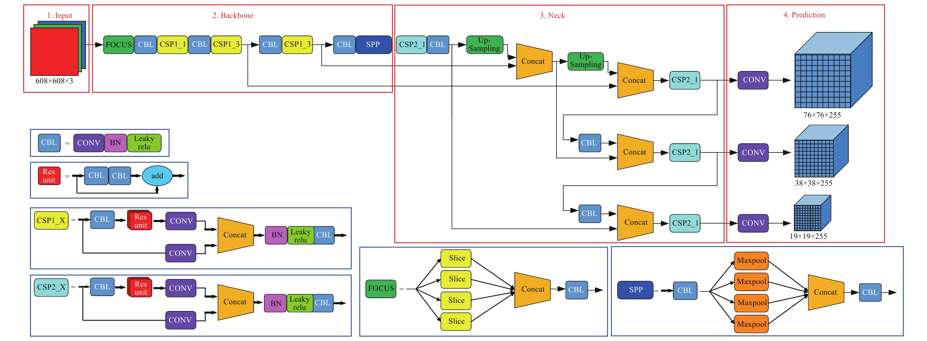
对于激光干扰效果评估的检测,相比于检测精度,检测速度往往具有更高的要求,所以文中选取了单阶段目标检测算法—YOLO[13-14]算法,并对不同程度的激光干扰进行了评估。Glenn于2020年6月提出了YOLOV5,该算法在继承算法系列优势的同时极大的简化了模型,在确保精度的同时提高了检测速度,为实现目标的实时检测奠定了良好的基础[11]。到目前为止,YOLOV5一共有YOLOV5s、YOLOV5m、YOLOV5l、YOLOV5x 四个网络模型。文中选取YOLOV5s的网络结构为代表,如图1所示,进行详细解析并实现应用。

图 1 YOLOV5s的网络结构
Figure 1. Network structure of YOLOV5s
由图1可知,YOLOV5模型主要分为四个部分:分别为In-put、Backbone、Neck和Prediction。
(1) In-put部分
In-put部分主要有Mosaic数据增强、图片尺寸处理、自适应锚框计算功能。
Mosaic数据增强就是随机选取四张图片,进行随机缩放再随机分布,最后进行拼接,极大的补充了检测数据集,特别是随机缩放为数据集增添了许多小目标,使得网络的鲁棒性更好。
图片尺寸处理是为了将原始图片统一缩放到标准尺寸,再送入检测网络中,网络模型统一标准尺寸一般为608×608×3。
自适应锚框计算则是YOLO算法系列中最具创新的部分,使得算法在每次训练时可自适应的计算不同训练集中的最佳锚框值。
(2) Backbone部分
Backbone部分主要由Focus结构和CSP结构组成。Focus结构比较关键的部分在于切片操作。在YOLOV5s中,将原始图像(608×608×3)输入Focus结构,进行切片操作后,首先变成304×304×12的特征图,然后经过一次32个卷积核的卷积操作,最终变成304×304×32的特征图。其中,YOLOV5s的Focus结构最后使用了32个卷积核,其他三种结构,使用的数量有所增加。
而在YOLOV5中融入了两种CSP结构,CSP1_X结构应用于Backbone主干网络,另一种CSP2_X结构则应用于Neck中。以此来提高CNN的学习能力,使得算法能轻量化的同时保持了较高的准确性。
(3) Neck部分
在目标检测领域,为了更好的提取融合特征,通常在Backbone和输出层,会插入一些层,这个部分称为Neck。Neck采用了FPN+PAN的结构,其中FPN是自上而下进行,通过上采样的方法对信息进行传递融合,从而得到预测的特征图。PAN是自底向上进行而得到的特征金字塔。
(4) Prediction部分
Prediction部分主要包括Bounding box损失函数和非极大值抑制(NMS)。
在YOLOV5中选用的损失函数为GIOU_Loss,其目的是为了解决了边界框不重合时问题。而使用加权NMS操作的目的是为了在预测结果处理时,从众多目标框的筛选出最优目标框,其原理是通过NMS推出最佳的预测框。每一个预测框都有一个得分,选取得分最高的预测框作为最终的检测结果,计算其余的预测框和最高得分的预测框的IOU,当结果大于阈值,则把对应的候选框剔除,再从剩余的候选框中选得分最大的作为另一个目标的检测结果,重复这个过程,直至剔除所有的预测框。
-
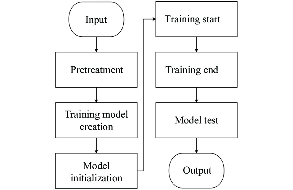
文中算法的流程有8个步骤,如图2所示。

图 2 激光干扰效果评估算法流程图
Figure 2. Flow chart of evaluation algorithm for laser jamming effect
(1)输入:将待检测激光干扰数据集输入到YOLOV5训练模型中;
(2)预处理:对输入图片进行图像筛选、图像增强及降噪处理;
(3)训练模型创建:创建激光干扰效果评估模型,检查训练和测试图片尺寸是否符合要求及设置好优化器参数后,加载预训练模型和权重。为达到提高训练精度的目的,可以通过设置cosine调度器,定义学习率衰减值,同时可以把混合精度训练加载入训练中;
(4)模型初始化:该部分主要包括训练集和测试集的载入、模型参数设置、类别统计、检查anchors是否存在及指数移动平均(EMA)等内容。在深度学习中,常常会使用指数移动平均(EMA)对模型的参数做平均,从而提高测试指标并增加模型鲁棒;
(5)训练开始:该部分主要包括获取参数(开始时间,batch size数量,epochs数量,图片数量)、加载图片权重(可选),定义进度条,设置偏差Burn-in,选择多尺度、前/反向传播、损失函数、优化器等参数,打印进度条,保存训练参数至tensorboard,计算mAP,保存训练结果及模型(best.pt和last.pt)等过程。同时经过对算法改良,不仅能够完成对目标进行标框分类,还实现了对检测出的区域面积占输入图像面积的百分比显示,达到了激光干扰效果评估更加直观化的效果;
(6)训练结束:返回的数值结果主要包括Box、Objectness(目标检测loss均值,值越小目标检测越准)、Classification(分类loss均值,值越小分类越准)、Precision(准确率,值越接近1分类越准)和Recall(召回率,值越接近1分类越准)、mAP@0.5和 mAP@0.5:0.95(AP是用Precision和Recall作为两轴作图后围成的面积,m表示平均,@后面的数表示判定IOU为正负样本的阈值,@0.5:0.95表示阈值取0.5:0.05:0.95后取均值);
(7)模型测试:将待测定图片输入到训练好的模型中进行检验测试,实现对图像受激光干扰区域进行特征标注,智能化、自动化完成激光干扰效果评估;
(8)输出:返回测试判定好的激光干扰效果评估图像。可直观反映激光干扰等级、干扰区域面积及识别精度等信息。
-
实验中激光干扰对象是内置式720 p HD摄像头,最大帧数30 fps,图像大小1 280×720,激光采用诺为N26激光笔,功率4 mW,波长650 nm。受干扰图像一般呈点状发散,干扰程度越大,发散的越厉害,对图像特征遮挡越严重,受轻微干扰的图像只有部分特征轻微失真,根据人眼直观感受及受干扰区域,将干扰程度分为四个等级,如图3所示。
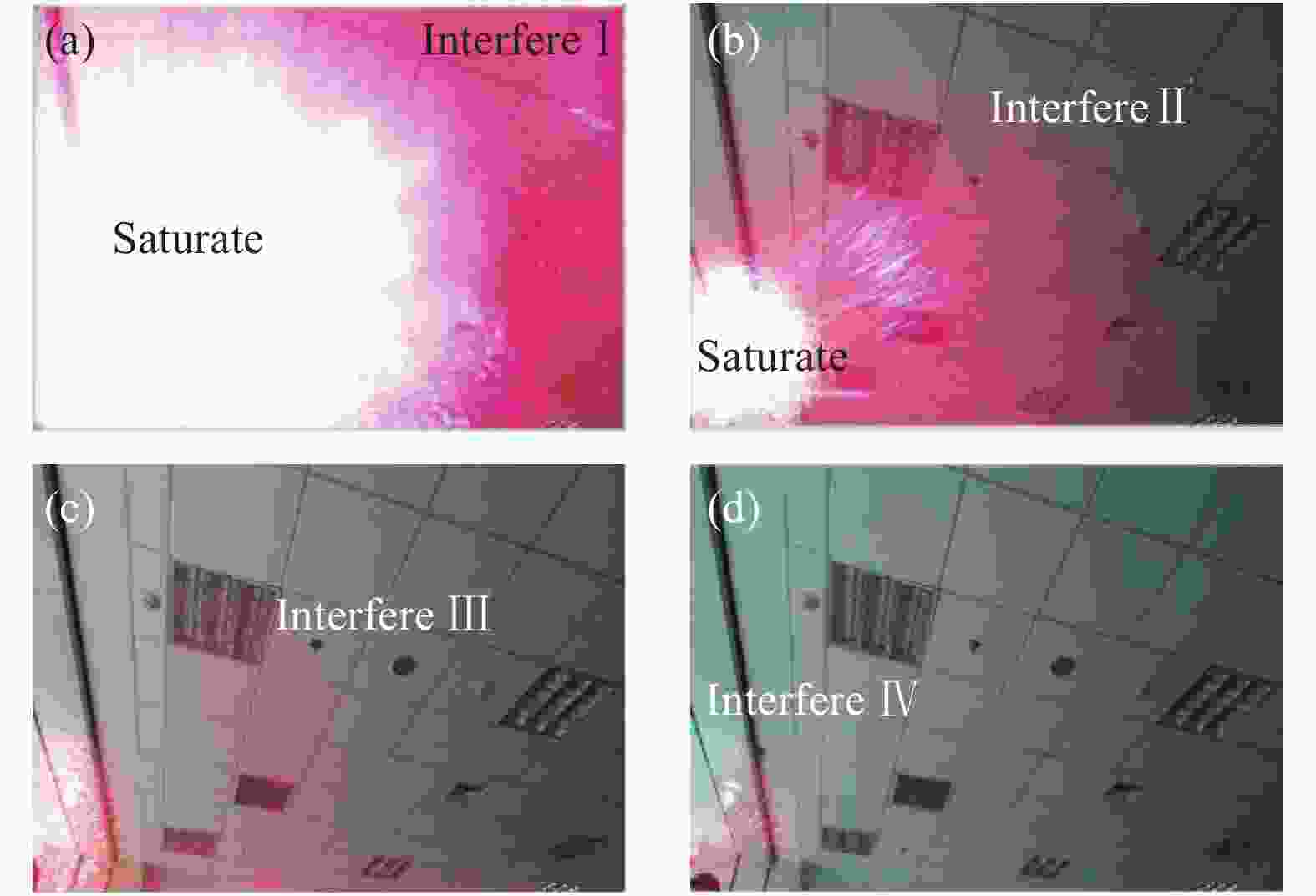
图 3 激光干扰效果不同等级划分图
Figure 3. Diagram of different grades of laser jamming effect
(1) Interfere I表示激光干扰等级为I级,即干扰区域产生严重失真,该区域内信息完全无法识别,干扰区域面积占总图像面积50%以上,如图3(a)所示。
$${\rm{Interfere\; I}} = \left\{ \begin{aligned} & \frac{{{S_{Ai}}}}{{{S_{Bi}}}} > 0.5 \\& \frac{{{H_{Ai}}}}{{{H_{Bi}}}} > 0.9 \end{aligned} \right.$$ (1) 式中:SAi表示干扰区域面积;SBi表示整幅图像面积;HAi表示受干扰时图像的信息熵;HBi表示未受干扰时图像的信息熵。
(2) Interfere II表示激光干扰等级为II级,即干扰区域产生较重失真,该区域内大部分信息由于受到干扰造成识别困难,且干扰区域面积不超过总图像面积50%,如图3(b)所示。
$${\rm{Interfere \; II}} = \left\{ \begin{aligned} & 0.3 < \frac{{{S_{Ai}}}}{{{S_{Bi}}}} < 0.5 \\& 0.5 < \frac{{{H_{Ai}}}}{{{H_{Bi}}}} < 0.9 \end{aligned} \right.$$ (2) (3) Interfere III表示激光干扰等级为III级,即干扰区域产生轻微失真,该区域内只有一小部分信息由于受到干扰造成识别困难,且干扰区域面积原则上不超过总图像面积30%,如图3(c)所示。
$${\rm{Interfere \; III }}= \left\{ \begin{split} & \frac{{{S_{Ai}}}}{{{S_{Bi}}}} < 0.3 \\& 0.2 < \frac{{{H_{Ai}}}}{{{H_{Bi}}}} < 0.5 \end{split} \right.$$ (3) (4) Interfere IV表示激光干扰等级为IV级,即干扰区域产生失真,该区域内出现因激光照射产生的杂散光而形成的微弱光斑,虽然对信息获取影响不大,但可作为激光干扰前的预警征兆,具有重要价值意义,如图3(d)所示。
$${\rm{Interfere \;IV}} = \left\{ \begin{aligned} & \frac{{{S_{Ai}}}}{{{S_{Bi}}}} < 0.1 \\ & \frac{{{H_{Ai}}}}{{{H_{Bi}}}} < 0.2 \end{aligned} \right.$$ (4) (5) Saturate表示激光干扰饱和区域,即干扰区域内像素饱和,形成明显光斑掩盖了区域内的所有信息,饱和区域是激光干扰达到最好效果的区域,效果如图3(a)、 (b)所示。
$$Saturate = \frac{{{H_{Ai}}}}{{{H_{Bi}}}} = 1$$ (5) 考虑不同的激光干扰方向,分别从30°、60°、90°在1.5~3 m处射入摄像头,并选取了3 020张受到来自不同角度和距离激光干扰后的图像作为总的数据集,数据集部分原图如图4所示。使用LabelImg对受激光干扰图像进行标注,分别对应四个等级。标注后的文件名以xml作为后缀,数据集采用VOC转YOLO格式,用于训练模型。

图 4 数据集部分原图
Figure 4. Part of the original image of the data set
生成训练集、验证集和测试集文件,比例是6∶2∶2。划分详情如表1所示。
表 1 激光干扰检测数据集划分
Table 1. Data set division of laser interference detection
Parameter Quantity (pieces) Total data set 3 020 Training set 1 812 Validation set 604 Test set 604 -
具体实验参数配置如表2所示。
表 2 实验参数配置
Table 2. Experimental parameter configuration
Parameter Configuration Operating system Linux Language Python 3.6 CUDA 10.2 -
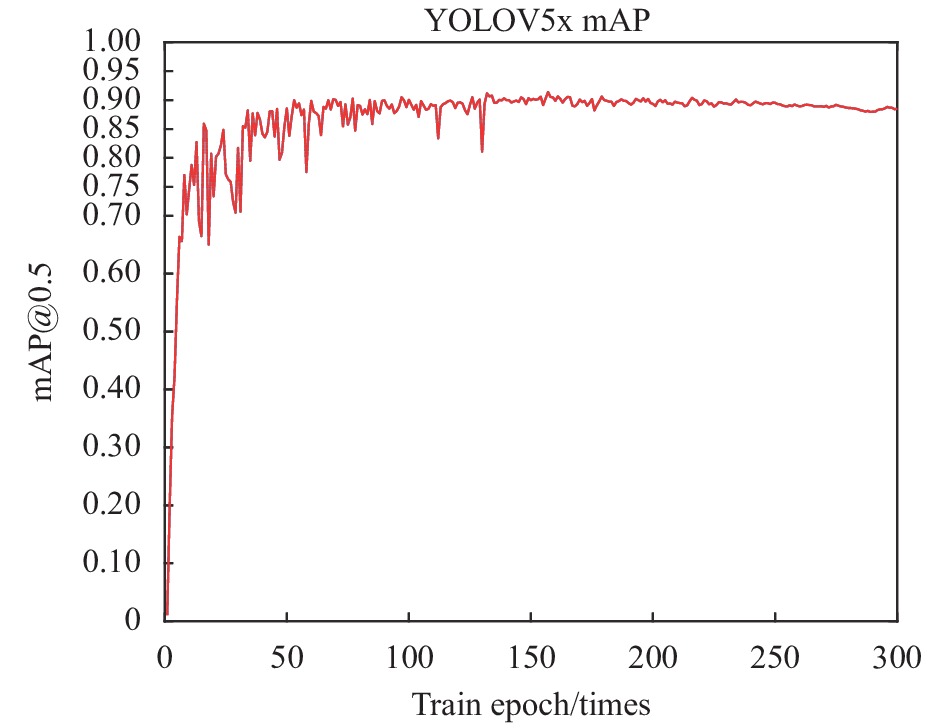
对标注好的2 416幅训练集和验证集图像进行训练,使其分别在YOLOV5x、YOLOV5l、YOLOV5m、YOLOV5s网络模型下训练300次。训练的得到的激光干扰效果评估模型参数结果如图5~图8所示。对比分析YOLOV5四种模型下的训练结果图,可更加直观的反映出不同网络模型训练出权重的差异。

图 5 YOLOV5x训练结果
Figure 5. YOLOV5x training results

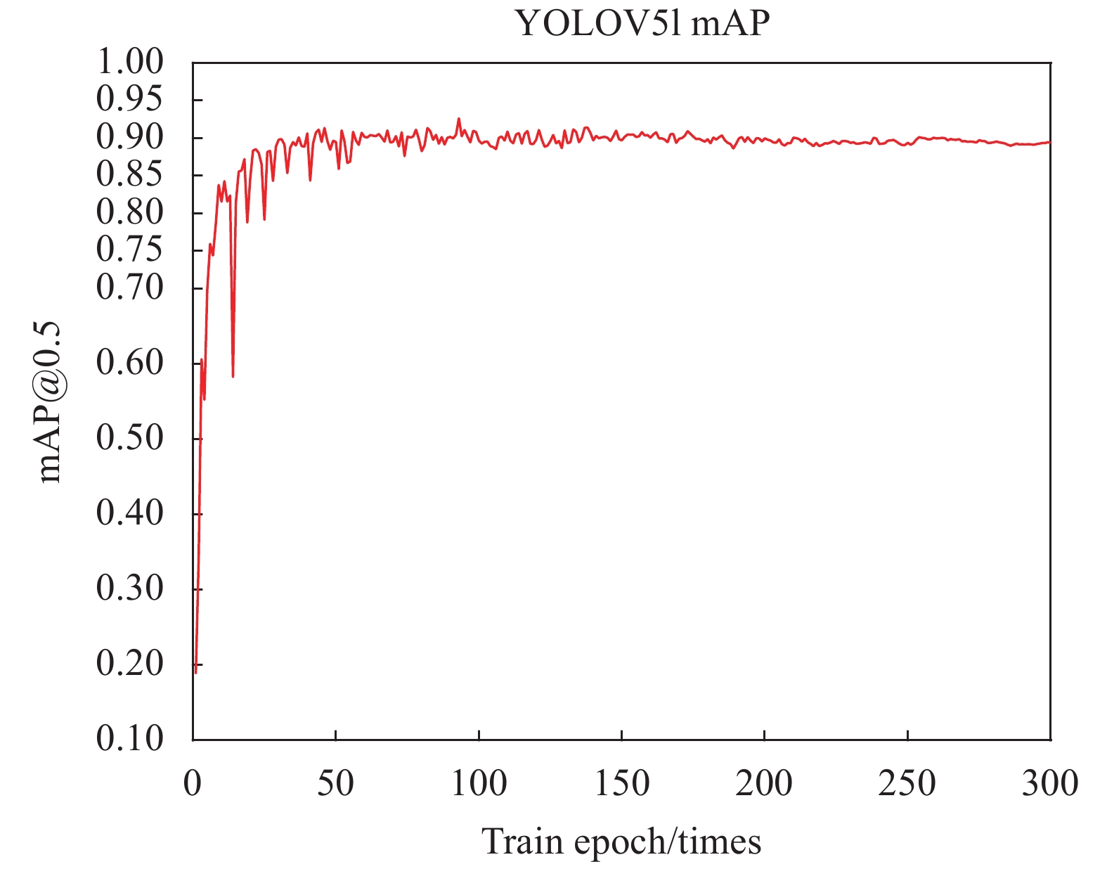
图 6 YOLOV5l训练结果
Figure 6. YOLOV5l training results

图 7 YOLOV5m训练结果
Figure 7. YOLOV5m training results

图 8 YOLOV5s训练结果
Figure 8. YOLOV5s training results
从不同模型训练下得到的激光干扰效果评估模型结果中可以观察到,在训练次数不断增加的过程中,YOLOV5s、YOLOV5m、YOLOV5l、YOLOV5x的准确率(mAP@0.5)都有较大的提升,且最后都能维持在90%左右。在训练过程中,YOLOV5m的mAP值变化最为剧烈,说明在训练次数较小时,由该网络训练的模型准确度不稳定;而YOLOV5x的mAP值变化最为平缓,说明在训练过程中,由该网络训练的模型准确度最为稳定。YOLOV5l与YOLOV5s则相对平缓。
-
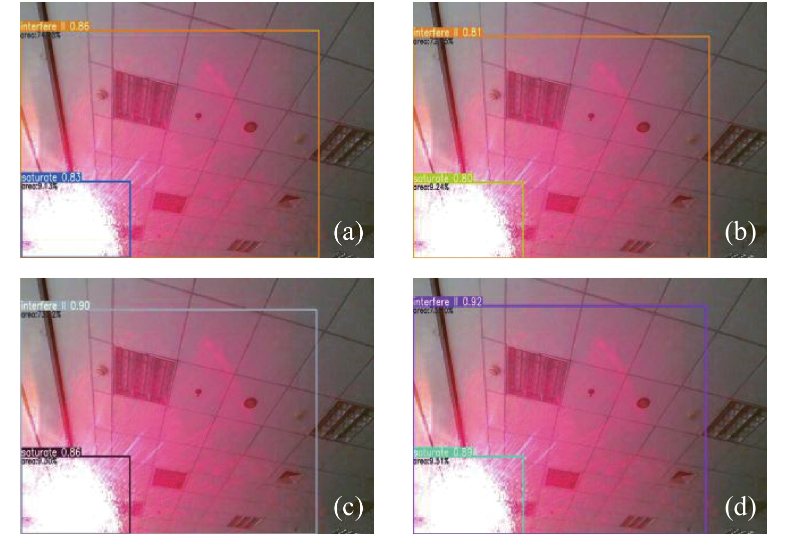
图像测试结果如图9所示。在604幅测试图像中随机选取一张受激光干扰图像对四种网络结构下训练出的激光干扰效果评估模型进行测试,结果如表3所示。

图 9 YOLOV5激光干扰测试效果图
Figure 9. YOLOV5 laser interference test renderings
表 3 激光干扰图像测试结果
Table 3. Laser jamming image test results
Network structure YOLOV5s YOLOV5m YOLOV5l YOLOV5x Time/s 1.119 1.208 1.282 1.367 Test results Fig.9 (a) Fig.9 (b) Fig.9 (c) Fig.9 (d) Recognition accuracy 0.86 0.81 0.90 0.92 从图9中可以观察出,无论选用何种网络模型进行训练,得到的模型都能对激光干扰效果进行有效评估。且识别精度均稳定在0.80以上。但不同网络模型训练下的测试结果仍存在差异,在识别所用的时间上,YOLOV5s所用时间最少,YOLOV5m、YOLOV5l、YOLOV5x所用时间逐渐增加;在识别精度上,YOLOV5x识别精度最高,可达到0.92,YOLOV5l、YOLOV5s识别精度较好,均达到0.85以上,YOLOV5m识别精度最低,仅能达到0.80以上。
对604幅测试图像进行测试,将文中的方法与目前常用的YOLOV3和YOLOV4目标检测方法进行了比较。得到数据结果如表4所示。
表 4 三种算法对激光干扰图像评估实验结果
Table 4. Experimental results of laser interference images with evaluate three algorithms
Algorithm Recognition accuracy Time/s YOLOV3 0.76 3.68 YOLOV4 0.80 2.37 YOLOV5 0.85 1.19 由表4可以看出,利用YOLOV5进行激光干扰效果评估所能达到的精度更高,所需检测时间更少。
综上所述,选用YOLOV5进行激光干扰效果评估,不仅能达到较高的识别精度,还能保证较快的识别速度,为激光干扰的实时检测提供了依据。但经不同网络模型训练得到的结果,所能达到的效果不同,YOLOV5x得到的模型训练精度最高,但模型最大,识别速度最慢;相较之下,YOLOV5s得到的模型训练精度和识别速度都较好,且模型最小。
-
文中深入探讨介绍了深度学习和YOLOV5网络模型结构的相关理论知识,并通过算法实现了在激光干扰效果评估上的应用,使此类激光干扰效果评估方法的评价结果更加符合人的主观感受,达到了预期目的。目前,对激光干扰效果的评估方法研究还处在起步阶段,制作的激光干扰数据集覆盖的激光和镜头类型还不够。目前只能针对激光干扰整体进行评价,在细节处理上存在不足之处,需要进行激光干扰图像上细节的划分,从而更好的完成激光干扰效果评估。另外,文中的数据集是角度不变的2 016张图像,类型完备且规模较大,但在实际应用中受干扰图像数量可能较少,无法进行大规模的有监督训练,因此,下一步将继续研究在小样本条件下如何进行激光干扰效果评估。
Evaluation method of laser jamming effect based on deep learning
-
摘要: 针对激光干扰效果评估受主观经验较大、难以定量评估的问题,提出了一种基于深度学习的激光干扰效果评估方法。首先,对YOLOV5算法进行了整体介绍,其次制作了来自不同角度、不同距离的3 020张激光干扰图像;然后,对标注的数据集进行训练,得到了激光干扰效果评估模型;最后,分别在YOLOV5x、YOLOV5l、YOLOV5m、YOLOV5s网络模型下训练300次,实验验证了模型的正确性。实验结果表明:利用训练好的模型实现了对激光干扰图像的效果评估,该模型不仅可以自动标注激光干扰区域和进行干扰效果等级评估,同时还融入了传统策略,可以通过计算标注区域面积占整幅图像面积的大小作为辅助决策,实现自动标注激光干扰区域面积所占百分比,识别准确度在80%以上,对激光干扰效果评估具有重要意义。Abstract: Aiming at the problem that the evaluation of laser jamming effect is influenced by subjective experience and difficult to evaluate quantitatively, a laser jamming effect evaluation method based on deep learning was proposed. Firstly, the overall introduction of the YOLOV5 algorithm was given. Secondly, 3 020 laser jamming image from different angles and distances were produced. Then, the labeled data sets were trained to obtain the laser jamming effect evaluation model. Finally, the model was trained 300 times under the network models of YOLOV5x, YOLOV5l, YOLOV5m and YOLOV5s respectively. The experimental results show that the trained model can be used to evaluate the effect of laser interference image. The model could not only automatically label the laser interference area and evaluate the interference effect level, but also integrate the traditional strategy. It could calculate the area of the labeled area in the whole image as an auxiliary decision. The percentage of laser jamming area was automatically marked. The recognition accuracy was more than 80%, which is of great significance to the evaluation of laser jamming effect.
-
Key words:
- laser jamming /
- effect evaluation /
- YOLOV5 algorithm /
- deep learning
-
图 2 激光干扰效果评估算法流程图
Figure 2. Flow chart of evaluation algorithm for laser jamming effect
表 1 激光干扰检测数据集划分
Table 1. Data set division of laser interference detection
Parameter Quantity (pieces) Total data set 3 020 Training set 1 812 Validation set 604 Test set 604  下载: 导出CSV
表 2 实验参数配置
Table 2. Experimental parameter configuration
Parameter Configuration Operating system Linux Language Python 3.6 CUDA 10.2
下载: 导出CSV
表 3 激光干扰图像测试结果
Table 3. Laser jamming image test results
Network structure YOLOV5s YOLOV5m YOLOV5l YOLOV5x Time/s 1.119 1.208 1.282 1.367 Test results Fig.9 (a) Fig.9 (b) Fig.9 (c) Fig.9 (d) Recognition accuracy 0.86 0.81 0.90 0.92
下载: 导出CSV
表 4 三种算法对激光干扰图像评估实验结果
Table 4. Experimental results of laser interference images with evaluate three algorithms
Algorithm Recognition accuracy Time/s YOLOV3 0.76 3.68 YOLOV4 0.80 2.37 YOLOV5 0.85 1.19
下载: 导出CSV
-
[1] He Xuan, Zhou Bing, Liu Hexiong, et al. Research status of laser suppression interference assessment [J]. Laser & Infrared, 2019, 49(7): 787-793. (in Chinese) doi: 10.3969/j.issn.1001-5078.2019.07.001 [2] Li Haiyan, Zhu Min, Lv Junwei, et al. Experiment research and theory analysis for off-axis laser disturbing CCD detection system [J]. Infrared and Laser Engineering, 2011, 40(5): 840-843. (in Chinese) doi: 10.3969/j.issn.1007-2276.2011.05.013 [3] Tang Wei, Wang Rui, Wang Tingfeng, et al. Laser jamming experiment of varifocal colour CCD imaging system [J]. Infrared and Laser Engineering, 2017, 46(4): 0406007. (in Chinese) doi: 10.3788/IRLA201746.0406007 [4] Sun Yunqiang, Cheng Xiang'ai, Wang Fei. Method of quality evaluation aimed at laser-disturbing image [J]. Infrared and Laser Engineering, 2007, 30(5): 659-662. (in Chinese) doi: 10.3969/j.issn.1007-2276.2007.05.020 [5] Qian Fang, Sun Tao, Guo Jin, et al. Laser interference effect evaluation algorithm based on feature point distribution characteristics [J]. Chinese Journal of Lasers, 2014, 41(5): 0509001. (in Chinese) [6] Qian Fang, Sun Tao, Guo Jin, et al. Evaluation of multiframe dynamic interference effects combined with laser power and spot position [J]. Chinese Journal of Lasers, 2014, 41(11): 1102001. (in Chinese) doi: 10.3788/CJL201441.1102001 [7] GAO Run, Niu Chunhui, Li Xiaoying, et al. Simulation and experimental study of 632 nm laser on CCD interference [J]. Laser & Infrared, 2016, 46(5): 552-557. (in Chinese) doi: 10.3969/j.issn.1001-5078.2016.05.008 [8] Zhang Chao, Zhang Wei, Wang Bin, et al. Experimental study on the interference of different wavelength lasers on CCD [J]. Laser Technology, 2014, 38(6): 826-829. (in Chinese) doi: 10.7510/jgjs.issn.1001-3806.2014.06.022 [9] 任立均. 光电成像系统激光干扰效果分析与评估技术研究[D]. 华中科技大学, 2019. Ren Lijun. Research on laser interference effect analysis and evaluation technology of photoelectric imaging system[D]. Wuhan: Huazhong University of Science & Technology, 2019. (in Chinese) [10] Schleijpen R, Heuvel J, Mieremet A L, et al. Laser dazzling of focal plane array cameras[C]//Proceedings of SPIE, 2007, 6543: 42. [11] Yang Xiwei, Tong Zhongcheng, Wang Yafu, et al. Modeling and simulation of laser jamming for electro-optical imaging guided seeker [J]. Infrared and Laser Engineering, 2011, 40(7): 1243-1248. (in Chinese) doi: 10.3969/j.issn.1007-2276.2011.07.011 [12] Liu Fei, Shao Xiaopeng, Han Pingli, et al. Quality assessment of the laser disturbing image utilizing cross entropy [J]. Journal of Xidian University, 2014, 41(5): 129-134. (in Chinese) [13] Redmon J, Divvala S, Girshick R, et al. You only look once: Unified, real-time object detection[C]//Proceedings of the IEEE Conference on Computer Vision and Pattern Recognition, 2016: 779-788. [14] Wang Yuning, Pang Zhiheng, Yuan Deming. Vehicle detection based on YOLO in real time [J]. Journal of Wuhan University of Technology, 2016, 38(10): 41-46. (in Chinese) doi: 10.3963/j.issn.1671-4431.2016.10.008 -

 点击查看大图
计量
- 文章访问数: 341
- HTML全文浏览量: 97
- PDF下载量: 55
- 被引次数: 0


