


 下载:
下载:


-
激光烧蚀微推力器(μLPT)是指通过透镜组将激光聚焦于工质上,形成局部高温高压区,进而喷射羽流形成冲量的推力器[1]。由于推力器自携激光器和工质,具有比冲高、结构紧凑、工作稳定可靠等优点,近年来在空间微推进领域受到广泛关注[2]。
激光与工质相互作用产生冲量的物理过程十分复杂[3],主要包括工质对激光能量的吸收、高温高压羽流演化、等离子体的生成[4]、激光与等离子体的相互作用等过程。影响激光烧蚀推进单脉冲冲量性能的主要因素包括激光的脉宽
$\tau $ 、波长$\lambda $ 、能量$E$ ,工质的比冲${I_{sp}}$ 、冲量耦合系数${C_m}$ ,以及激光光路特性等因素。围绕μLPT的工程化问题,国内外在工质层面、靶结构及其供给系统层面开展了广泛的研究[5]。常见的工质有金属工质、聚合物工质、含能工质等类型。一般情况下,金属类工质具有较高的比冲和较低的冲量耦合系数,聚合物工质具有较高的冲量耦合系数和较低的比冲[6]。国内外学者还对大量常见材料进行了推力性能测试,发现一般情况下原子量越小,比冲越大。含能工质因为在烧蚀过程中可以释放自身蕴含的化学能[7],可以有效提升推力和冲量耦合系数。
靶结构是指激光烧蚀推进工作过程中,激光的聚焦区域及其周围支持性结构。除了工质本身,靶结构设计还包含基底材质、约束结构、涂覆工艺等问题,对于推力性能有重要影响[8]。供给系统主要是指推力器中使激光聚焦点在靶上位移,从而使推力器连续工作的机电装置。供给系统的需要根据激光光路、工质物态、靶结构形态等条件进行针对性的设计。对于液态工质,常用的供给系统为压力式供给:采用压力容器灌装液态工质,通过微型阀门出口的流量,像“挤牙膏”一样把工质连续少量地供给到光路的聚焦点上。压力式供给可避免机械运动给推力器带来的不必要角动量,结构上也较为简单实用。难点在于液体靶材的黏度调控:黏度太大则靶材很容易堵塞管路,黏度太小则羽流喷射时液体飞溅十分严重,不仅损失比冲,还极易使激光光学系统受到污染[9],如图1所示。

图 1 压力供给式液态推进剂的μLPT
Figure 1. Liquid propellant μLPT fed by pressure
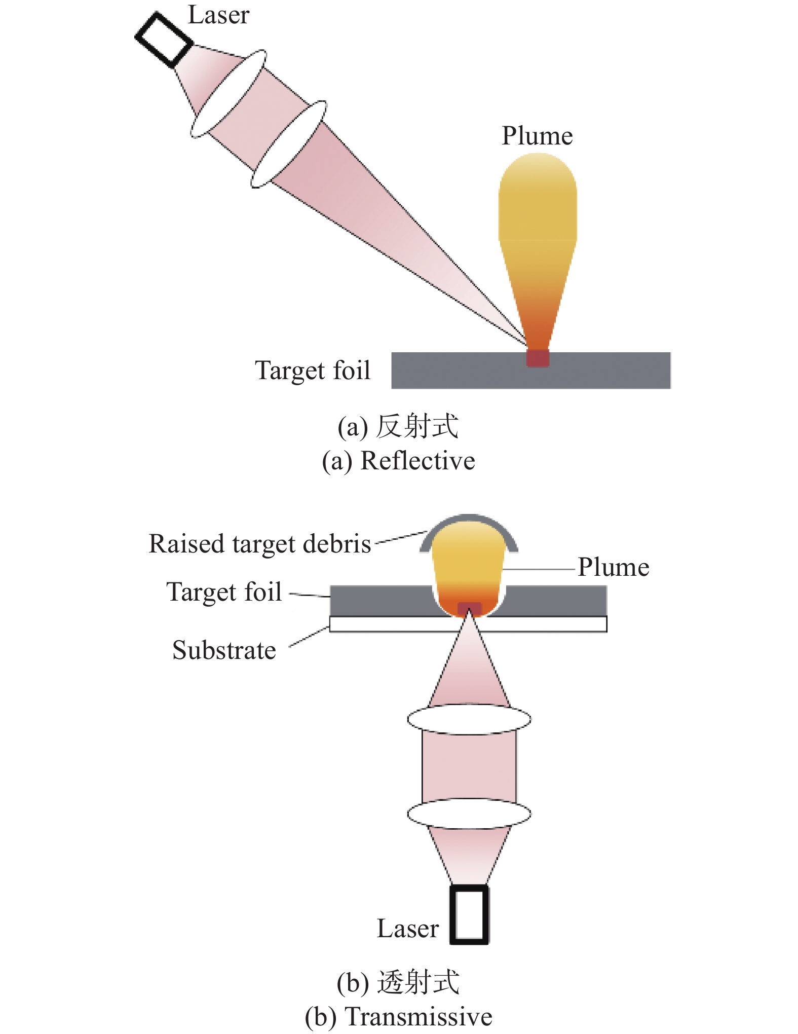
对于固态工质,靶结构主要分为块体、薄膜型和约束型。块体靶是一整块工质,激光直接聚焦在靶表面上形成沿靶表面法线向外的冲量,与激光入射方向相反,因此这种激光入射方式也称为反射式激光烧蚀。反射式激光烧蚀结构比较简单,但由于光学系统在羽流喷射范围内,即使错开一定角度也容易受到羽流的污染导致激光聚焦性能下降,比较适合金属等羽流清洁、碎片较少的工质。如图2(a)所示。薄膜型靶的工质均匀涂覆在透明基底上形成薄膜,激光从透明基底的一侧透射,在工质薄膜上聚焦,在基底的另一侧形成冲量,这种激光入射方式也称为透射式激光烧蚀[10]。如图2(b)所示。透射式激光烧蚀羽流与光学系统在靶面两侧,可有效减弱羽流对光学系统的污染,在含能工质激光烧蚀微推力器中应用较为广泛[11-12]。约束型靶的工质装载在预先制作的靶坑阵列中,工质在烧蚀喷射时,羽流由于受到靶坑壁的约束作用,在出口处的速度得到提升,工质比冲和效率也相应增大。约束型靶的靶坑阵列制作复杂,且对激光聚焦精度、靶坑装药量、靶坑结构都有较为严格的要求,目前在推力器工程化上还存在较大难度。

图 2 反射式与透射式激光烧蚀推进
Figure 2. Reflective and transmissive laser ablation propulsion
对于薄膜型靶[13],供给系统主要取决于基底的材质,对于柔性基底(如聚氯乙烯),传统上一般采用卷带式供给。如图3所示,待烧蚀的工质卷带缠绕在辊筒上。辊筒的转动带动卷带上的工质连续通过聚焦点,使推力器连续工作。2002年,Phipps成功研制出了第一台毫秒脉宽卷带式μLPT原理样机[14],其半导体激光器功率约5 W,2006年,Phipps团队又对原理样机进行了改进[15],激光功率增长到80 W,工质为聚氯乙烯(PVC)和聚叠氮缩水甘油醚(GAP)。这两型μLPT在40 ℃下的平均寿命超过10 000 h。可以基本满足微小卫星推力器低功耗、长寿命推进需求。

图 3 卷带式μLPT示意图
Figure 3. Schematic diagram of tape type μLPT
卷带式μLPT存在的关键问题是基底是柔性的,在羽流喷射的过程中会吸收冲量,转化为推力器不稳定的振动,此外,柔性基底强度不足,在高能脉冲激光作用容易破裂。为了解决这些问题,Phipps又提出采用刚性基底的碟片式μLPT方案。如图4所示,工质涂覆在透明硬质碟片上,制成靶盘,靶盘固定在转轴上,转轴则固定在水平电机上。激光光路保持固定,通过转轴转动和电机平动可实现烧蚀点在靶面上的二维运动。Phipps设计的纳秒脉宽碟片式μLPT烧蚀金的推力约为0.63 μN,比冲约为3660 s,烧蚀铝的推力约为0.94 μN,比冲约为1120 s[16]。

图 4 碟片式μLPT示意图
Figure 4. Schematic diagram of disk type μLPT
碟片式μLPT的靶盘为刚性平面结构,无法折叠储纳,靶结构的比表面积较低,使推力器总冲受限。因此,如何提高碟片靶面上烧蚀点数量,提升靶面的利用率和总冲,是碟片式μLPT工程化设计亟待解决的问题。
-
靶盘式激光烧蚀微推力器的主要结构包括工质供给模块、激光器功能模块和控制模块三部分。激光器功能模块通过电光转化生成激光,激光聚焦在靶盘上形成烧蚀点和冲量;如图5所示,工质供给模块通过轴向和切向步进电机的运动实现激光聚焦点在靶盘上的运动,使推力产生连续独立的冲量;控制模块对内实现激光出光与靶盘转动的配合,监测推力器工作状态,对外通过接口实现能量、信息的交互。

图 5 碟片式μLPT实物图
Figure 5. Physical drawing of disk type μLPT
推力器的单脉冲冲量
${I_s}$ 主要受激光脉冲能量${E_l}$ 和冲量耦合系数${C_m}$ 影响。$$ {I_s} = {E_l} \cdot {C_m} $$ (1) 对于一个工质成分均一、靶材涂覆均匀、聚焦光路固化的微推力器,单脉冲冲量基本稳定不变。总冲
${I_t}$ 是单脉冲冲量与烧蚀点数量之积,则:$$ {I_t} = {I_s} \cdot N $$ (2) 靶盘上每一个烧蚀点可看成是圆形的,靶盘利用率为:
$$ \eta = \frac{{N \cdot {\rm{\pi }}r_a^2}}{{{S_t}}} $$ (3) 式中:
${r_a}$ 为烧蚀点半径;${S_t}$ 为靶面总面积,对于圆环形靶面有:$$ {S_t} = {\rm{\pi }}\left( {r_o^2 - r_i^2} \right) $$ (4) 式中:
${r_i}$ 为靶盘内半径;${r_o}$ 为靶盘外半径。可见,如何合理设计靶盘上烧蚀点分布,使靶盘上容纳更多的烧蚀点,成为提高靶盘利用率和推力器总冲的关键。针对这一问题,文中提出了串珠法和套圈法两种分析方法,并设计了三种具体烧蚀点分布方式,以下具体说明。
-
(1)根据靶面形状建立坐标系;
(2)确定烧蚀点运动的路径方程,可以是连续的,也可以是分段的;
(3)在路径方程上,第n个烧蚀点与第n+1,n-1个烧蚀点圆心之间的距离为ra,根据该约束条件和路径方程通过解析或迭代的方法得到第n个点的位置坐标。
(4)计算烧蚀点总数及靶面利用率。
这种方法关键在于先确定烧蚀点的运动路径,再在路径上确定每一个烧蚀点的位置坐标,就像先固定串线的骨架,把每个珠子串起来一样。下面通过圆圈路径和螺旋路径分别说明串珠法的具体实施过程。
-
如图6所示,建立以靶盘中心为圆心的极坐标系,在烧蚀点一圈内沿圆路径运动,轴向静止,仅切向转动。相邻两圈的半径之差为2ra。
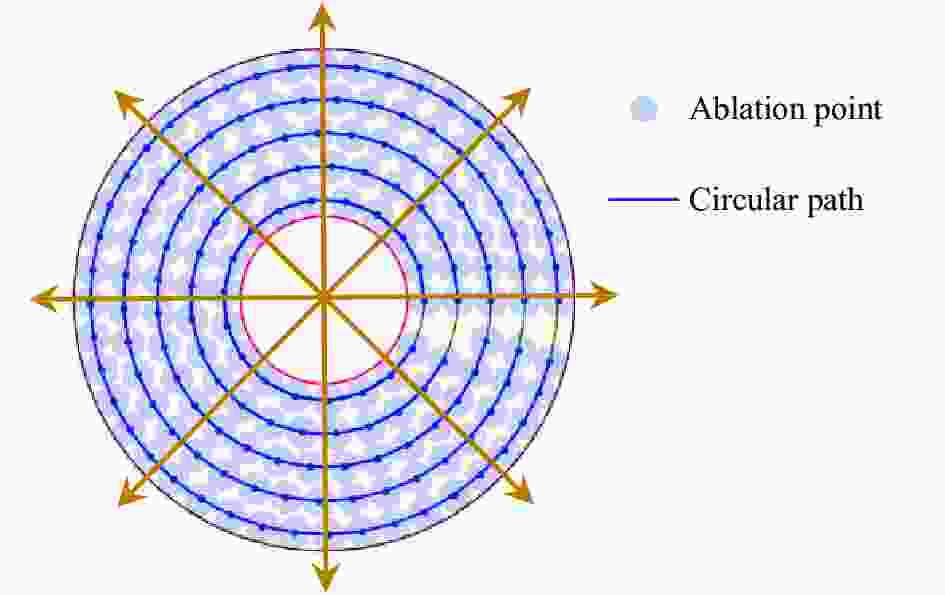
图 6 圆圈路径的烧蚀点分布
Figure 6. Distribution of ablation point of circular path
从外向里数,靶盘上能容纳的所有的圆圈半径分别为:
$$ {r_o} - {r_a},{r_o} - 3{r_a}, \ldots ,{r_o} - \left( {2n - 1} \right){r_a}, \ldots ,{r_o} - \left( {2m - 1} \right){r_a} $$ (5) $$ m = \left\lfloor {\frac{{{r_o} - {r_i}}}{{2{r_a}}}} \right\rfloor $$ (6) 第n圈上,相邻两个烧蚀点圆心之间的距离为2ra,对应的弧度为:
$$ {k_{na}} = \arcsin \left( {\frac{{2{r_a}}}{{{r_o} - \left( {2n - 1} \right){r_a}}}} \right) $$ (7) 则第n圈上能容纳的烧蚀点数量为:
$$ {N_n} = \left\lfloor {\frac{{2{\rm{\pi }}}}{{{k_{na}}}}} \right\rfloor $$ (8) 整个靶盘烧蚀点总数Nd及推力器的总冲It分别为:
$$ {N_d} = \sum\limits_{n = 1}^m {{N_n}} $$ (9) $$ {I_t} = {N_d} \cdot {I_s} $$ (10) 式中:Is为单烧蚀点形成的冲量。
需要指出的是,从里向外数的情况,即所有的路径圆圈半径分别为:
$$ {r_i} + {r_a},{r_i} + 3{r_a}, \cdots ,{r_i} + \left( {2n - 1} \right){r_a}, \cdots ,{r_i} + \left( {2m - 1} \right){r_a} $$ (11) $$ m = \left\lfloor {\frac{{{r_o} - {r_i}}}{{2{r_a}}}} \right\rfloor $$ (12) 总圈数与从外向里数一致,每一圈的半径相等或更小,因此从外向里数更加合理。
-
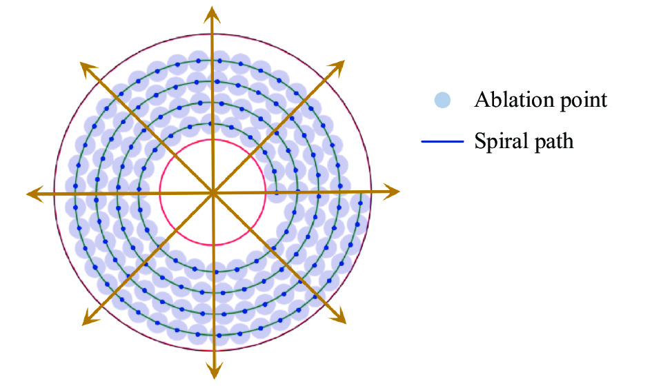
采用圆圈路径时,轴向运动仅在烧蚀点跨圈运动时发生,在实际应用中对轴向电机瞬时加减速要求较高,且可能导致推力器本身角动量不稳定。可以考虑采用螺旋路径改善这一问题。如图7所示,轴向和径向电机逐点动作,当切向运动一圈后,轴向恰好也运动到了下一圈次。则烧蚀点运动的路径符合螺旋线方程,记烧蚀点圆心的位置矢量P在极坐标系下的位置坐标为(R, θ), R 为轴向位置坐标, θ 为切向位置坐标。则R与θ满足:
$$ R = {r_i} + \left( {\frac{\theta }{{\rm{\pi }}} + 1} \right){r_a} $$ (13) 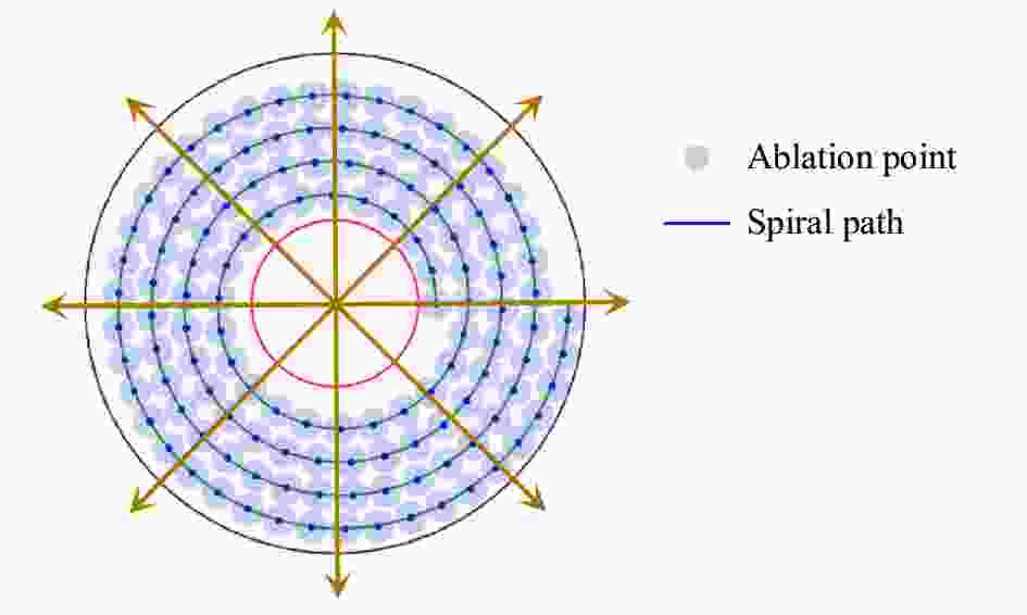
图 7 螺旋路径的烧蚀点分布
Figure 7. Distribution of ablation point of spiral path
螺旋线上的相邻两烧蚀点Pn,Pn+1之间的距离等于2倍烧蚀点半径,即
$$ \sqrt{R_n^2 + R_{n + 1}^2 - 2{R_n}{R_{n + 1}}\cos \left( {{\theta _n} - {\theta _{n + 1}}} \right) }= 2{r_a}$$ (14) 起始烧蚀点P1和终止烧蚀点PM分别满足:
$$\left\{ \begin{aligned} &R_1=0\\ &R_M \leqslant r_o-r_a\\ &R_{M+1} > r_o-r_a \end{aligned} \right.$$ (15) 基于公式(14)的迭代关系和公式(15)的边界条件,可迭代计算找到终止烧蚀点PM,以及所有烧蚀点的位置坐标。
-
串珠法基于平面几何方法,直接计算得到烧蚀点运动路径和所有烧蚀点位置坐标,对后续的工程机电控制设计比较友好。设当前路径的曲率半径为R,则当前路径上一个面积为
${\rm{\pi }}r_a^2$ 的圆形烧蚀点实际占据的面积为$$ {s_r} = \arcsin \left( {\frac{{2{r_a}}}{R}} \right) \cdot \left[ {{{\left( {R + {r_a}} \right)}^2} - {{\left( {R - {r_a}} \right)}^2}} \right] $$ (16) ${s_r}$ 随R增大而减小,如图8所示,当R趋向于无穷大时,${s_r}$ 有最小值$4r_a^2$ ,因此,串珠法分布的烧蚀靶平面利用率η的上限为:$$ {\eta _m} = \frac{{{\rm{\pi }}r_a^2}}{{4r_a^2}} \approx 78.54{\text{% }} $$ 
图 8 串珠法单点占据的面积
Figure 8. Area occupied by single point with string beads method
此外,对于圆圈路径,靶面的内外半径之差不是2ra的整数倍时,会出现“空圈”,靶面一圈内烧蚀点之间弧度差不能被2π整除时,会存在“空点”。对于螺旋路径,在靶面内外边缘,都会存在狭长的空白区域,导致靶面的利用率进一步降低。为了优化靶平面利用率,该节介绍一种基于平面圆的密排原理的烧蚀点分布分析方法,可以在平面上实现靶平面的最大化利用。
-
圆的平面密排[17]又称六角密排,即当平面上圆以图9所示的方式聚集时,平面上圆的排布达到最密。

图 9 平面上圆的六角密排
Figure 9. Hexagonal close pack of circles in plane
此时,连接相邻六个圆的圆心相邻构成六边形,可以看成每个圆在平面上实际占据了一个外接正六边形的面积。无限多的密排圆对无限大的面积利用率
${\eta _h}$ 为:$$ {\eta _h} = \frac{{{\rm{\pi }}{r^2}}}{{6/\sqrt 3 {r^2}}} \approx 90.64 \text{% } $$ (17) 而有限数量的密排圆对于有边界平面的面积利用率与边界处形状有关,对于凸多边形或者圆形边界,其面积利用率η一般比ηh小。下面以靶面的实际形状为边界,说明套圈法的具体实施过程。
(1)建立计算域Ω。在直角坐标系上建立边长为ro+2ri的矩形计算域Ω,Ω可完全覆盖靶面。
(2)在Ω上密排圆。在坐标原点处以ra为半径建立中心圆,中心圆所在行为中心行,在中心行上自中心圆向x轴正方向密排圆,可容纳的圆数量Nr为:
$$ {N_r} = \left\lfloor {\frac{{{r_o} + {r_a}}}{{2{r_a}}}} \right\rfloor $$ (18) 中心行上可容纳的圆总数为2Nr+1。在Ω上自中心行向y轴正方向密排行,可容纳的行数量Nc为:
$$ {N_c} = \left\lfloor {\frac{{{r_o} + {r_a}}}{{\sqrt 3 {r_a}}}} \right\rfloor $$ (19) Ω上可容纳的行总数为2Nc+1。Ω所有密排圆的分布如图10所示。

图 10 六角密排的烧蚀点分布
Figure 10. Distribution of ablation point of hexagonal close pack
(3)对Ω上的所有密排圆建立二维行列索引,并确定圆心坐标。中心行记为第0行,中心圆所在列记为第0列,中心圆索引为[0,0]。则第i行、第j列圆的索引为[i,j]。其圆心在直角坐标系上的坐标为(cxi,cyj),i为偶数时,有:
$$ \left\{ {\begin{array}{*{20}{l}} {c{x_i} = 2j \cdot {r_a}}\\ {c{x_j} = \sqrt 3 i \cdot {r_a}} \end{array}} \right. $$ (20) i为奇数时,有:
$$ \left\{ {\begin{array}{*{20}{l}} {c{x_i} = \left( {2j + 1} \right) \cdot {r_a}}\\ {c{x_j} = \sqrt 3 i \cdot {r_a}} \end{array}} \right. $$ (21) (4)建立可行域δ, δ为圆环内边界与外边界之间的区域。
(5)逐一判断密排圆是否在δ内,判别式为:
$$ \left\{ {\begin{array}{*{20}{l}} {cx_i^2 + cy_j^2 < = {{\left( {{r_o} - {r_a}} \right)}^2}}\\ {cx_i^2 + cy_j^2 > = {{\left( {{r_i} + {r_a}} \right)}^2}} \end{array}} \right. $$ (22) 所有δ内的密排圆即可视为可行的烧蚀点分布。
从上述套圈过程中可以看出,可行域的“圈”套出的六角密排的阵列,其内部已达到紧密排列,仅在可行域边界存在一些“毛刺”,可有效提高靶面利用率。
-
套圈法得到的烧蚀点分布,其靶面利用率理论上最高可达90.64%,优于串珠法的78.54%。此节通过计算,具体说明在实际条件下,套圈法对靶面利用率的优化情况。
-
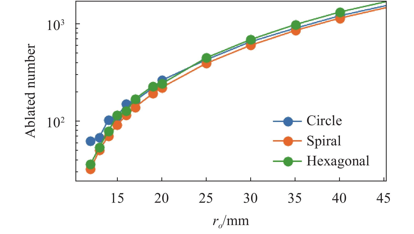
设烧蚀点半径ra=1 mm,靶面内半径ri=8 mm,计算圆圈路径、螺旋路径和六角密排三种分布方式的烧蚀点数量n和靶面利用率η随靶面外半径ro的变化,结果分别如图11、图12所示。

图 11 烧蚀点数量随ro的变化
Figure 11. Variation of number of ablation points with ro

图 12 靶面利用率η随ro的变化
Figure 12. Variation of target surface utilization rate η with ro
随着ro的增大,三种分布方式的烧蚀点数量快速增大。ro<14 mm时,圆圈路径烧蚀点数量最大,六角密排次之,螺旋路径最小;ro>25 mm时,六角密排烧蚀点数量最大,圆圈路径次之,螺旋路径最小。
对于圆圈路径,当ro−ri可被2ra整除时,η与上限接近,随着ro增大略微增大。当ro−ri不可被2ra整除时,由于靶盘上存在无法被利用的空圈,η显著低于整除的情况,但总的来看依然随ro增大而增大。
对于螺旋路径,随着ro的增大,η单调增大趋向于其上限,并且与圆圈路径的η越来越接近。
对于六角密排,ro很小时,其η比圆圈路径小,仅略高于螺旋路径。这是由于当靶面边界曲率半径很小时,边界附近存在大量因形状不匹配而无法容纳六角密排圆的靶面,致使靶面利用率降低。而随着ro的增大,六角密排的η快速增大,当ro>25 mm时,η已超越串珠法的上限,ro继续增大时,η逐渐趋向于套圈法的上限。
-
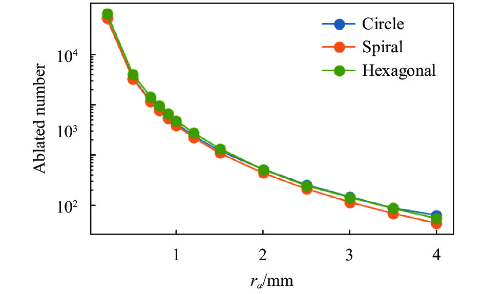
设靶面外半径ro=40 mm,靶面内半径ri=8 mm,计算圆圈路径、螺旋路径和六角密排三种分布方式的烧蚀点数量n和靶面利用率η随烧蚀点半径ra的变化,结果分别如图13、图14所示。

图 13 烧蚀点数量随ra的变化
Figure 13. Variation of number of ablation points with ra
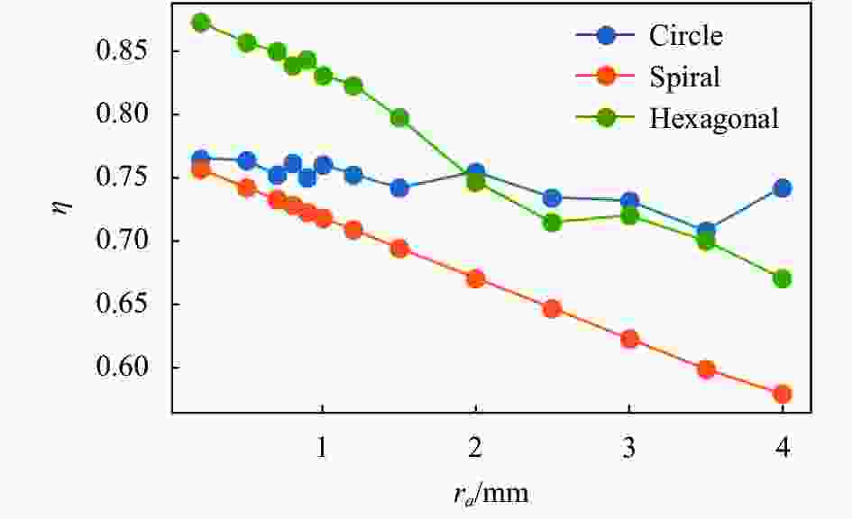
图 14 靶面利用率η随ra的变化
Figure 14. Variation of target surface utilization rate η with ra
随着ra的增大,三种分布方式的烧蚀点数量快速减小。ra<2 mm时,六角密排烧蚀点数量最大,圆圈路径次之,螺旋路径最小;ra>3.5 mm时,圆圈路径烧蚀点数量最大,六角密排次之,螺旋路径最小。
对于圆圈路径,η随着ra的变化不显著,基本维持在75%左右。对于六角密排和螺旋路径,随着ra的增大,η总体呈下降趋势,螺旋路径的线性度更好。当ra<2 mm时,六角密排相对另外两种分布η优势明显。
-
通过4.1和4.2两节的计算结果可知,三种不同烧蚀点分布的特点如下:
对于圆圈分布,其靶面利用率主要取决于靶面尺寸与烧蚀点尺寸的匹配程度:靶面圆环内外径差恰等于烧蚀点直径的整数倍时,靶面利用率接近最优。而当该条件不满足时靶面利用率会显著下降。这说明,应用圆圈路径设计靶面烧蚀点分布时,应尽可能保证靶面尺寸与烧蚀点尺寸的相匹配,控制空圈的面积。对于螺旋路径,其靶面利用率主要取决于靶面尺寸与烧蚀点尺寸的悬殊程度:靶面尺寸远大于烧蚀点尺寸时,靶面利用率接近圆圈路径;靶面尺寸远接近烧蚀点尺寸时,靶面利用率远小于其他两种分布方式,且整个变化过程单调、平滑。这说明,对于靶面较大聚焦性能较强的推力器,可以考虑应用螺旋路径来设计靶面烧蚀点分布,虽牺牲了少量的效率,但可使系统运行更加稳定可靠。
对于六角密排,其靶面利用率主要取决于靶面边界形状与六角密排格局的契合程度,表现在圆环靶面上即为:当靶面尺寸较小时,外径曲率半径也较小,边界形状与六角密排格局“格格不入”,边界处自然存在大量无法利用的“异形”区域,导致靶面利用率较低。而当靶面尺寸较大时,边界较为平直规则,可容纳较多的密排圆,这时六角密排的靶面利用率优势才能体现出来。总的来看,靶面越大,烧蚀点越小,六角密排的应用价值越大。
-
文中围绕碟片式激光烧蚀微推力器靶面利用率的优化问题,提出了串珠法和套圈法两种分析方法,并基于串珠法设计了圆圈路径、螺旋路径两种烧蚀点分布方式,基于套圈法设计了六角密排的烧蚀点分布方式。通过计算分析得出了不同分布方式的主要特点和应用场合,为碟片式靶面的充分利用提供了理论指导和设计参考,对推力器的工程化设计有一定借鉴意义。文中提出的方法主要针对碟片式激光烧蚀推力器,但对其他形状的薄膜靶,乃至烧蚀点平面分布的块体靶、约束式靶结构也有一定的参考价值。
从计算结果可以看出,对于固定形状和面积的靶面,适当减小烧蚀点面积对于提升烧蚀点数量和总冲效果明显。能否通过减小激光脉冲能量,牺牲一定的单脉冲性能,而增加烧蚀点数量来增大推力器的总冲,是后续研究方向。另一方面,六角密排分布虽然在理论上效率更高,烧蚀点分布坐标也已知,可以基于电机的切向和轴向运动工程实现,但在具体路径设计上还需要考虑运动的平滑性与精确性等问题,需要在未来进一步研究。
Optimization of target plate utilization of disk-type laser ablation microthrusters
-
摘要: 碟片式激光烧蚀推力器的总冲与靶盘上烧蚀点数量线性相关,提高靶盘利用率有利于在有限的靶面上得到更多的烧蚀点。为了优化靶盘利用率,文中首先对激光烧蚀微推力器进行了结构设计和分析,对靶盘上的烧蚀点分布问题进行了理论建模,提出了串珠法和套圈法两种分析方法,分别设计了圆圈路径、螺旋路径和六角密排三种实际烧蚀点分布方式。通过计算,分析比较了三种分布方式下,靶盘尺寸和烧蚀点尺寸对靶盘利用率的影响规律。结果表明,六角密排的靶盘利用率理论最高可达90.64%,圆圈路径和螺旋路径的靶盘利用率理论最高可达78.54%;靶盘利用率受到靶盘尺寸和烧蚀点尺寸的影响,靶盘尺寸较小时,圆圈路径的靶盘利用率相对较大,靶盘尺寸较大时,六角密排的靶盘利用率较大;三种分布方式各有特点,在应用上各有侧重。该研究为充分利用碟片式激光烧蚀推力器的靶盘提供了理论指导和设计参考,对推力器的工程化设计有一定借鉴意义。Abstract: The total impulse of a disc-type laser ablation thruster is linearly related to the number of ablation points on the target disk, and improving the utilization rate of the target disk is beneficial to obtain more ablation points on the limited target disk surface. In this paper, to optimize the utilization rate of the target disk, the structure of the laser ablation microthrusters was designed and analyzed. The distribution of the ablation point on the target disk was theoretically modelled, two analytical principles, namely, the bead principle and the collar principle, were proposed, and three actual ablation point distribution methods, namely, the circle path, the spiral path and the hexagonal pack, were designed. Through calculation, the influence law on the utilization rate of the target disk by the size of the target disk and the size of the ablation point under the three distribution methods was analyzed and compared. The results show that the target disk utilization rate of the hexagonal pack can reach up to 90.64%, and the target disk utilization rate theory of the circle path and spiral path can reach up to 78.54%. The target disk utilization rate is affected by the size of the target disk and the size of the ablation point. When the size of the target disk is small, the target disk utilization rate of the circle path is relatively large. When the size of the target is large, the target disk utilization rate of the hexagonal pack is relatively large. Each of the three distribution methods has its own characteristics and has its own emphasis on application. The research provides theoretical guidance and a design reference for the full utilization of the target disk of the disc-type laser ablation thruster, and has some reference significance to the engineering design of the thruster.
-
Key words:
- microthrusters of laser propulsion /
- hexagonal pack /
- utilization rate /
- path
-
[1] 杜邦登, 邢宝玉, 叶继飞, 等. 纳秒激光烧蚀金属推进性能的实验研究[J].红外与激光工程, 2020, 49(S2):147-154. doi: 10.3788/IRLA20200086 Du B D, Xing B Y, Ye J f, et al. Experiment investigation of propulsion performance of metals ablated by nanosecond laser [J]. Infrared and Laser Engineering, 2020, 49(S2): 20200086. (in Chinese) doi: 10.3788/IRLA20200086 [2] 金星, 吴文堂, 周伟静, 等. 用于脉冲微推力器的枢轴式微冲量测量系统设计方法[J]. 红外与激光工程, 2019(A01):103-109. doi: 10.3788/IRLA201948.S1170005 Jin X, Wu W T, Zhou W J, et al. Design method of micro-impulse measuring system based on pivots for pulsed micro-thruster [J]. Infrared and Laser Engineering, 2019, 48(S1): S1170005. (in Chinese) doi: 10.3788/IRLA201948.S1170005 [3] 陈敏孙, 江厚满. 切向空气气流对激光烧蚀碳纤维复合材料过程的影响[J]. 光学精密工程, 2011, 19(2):482-486. doi: 10.3788/OPE.20111902.0482 Chen M X, Jiang H M. Influence of tangential airflows on process of laser ablating carbon-fiber composites [J]. Optics and Precision Engineering, 2011, 19(2): 482-486. (in Chinese) doi: 10.3788/OPE.20111902.0482 [4] Yu Z, Wu J, Zhang D, et al. Investigation on plume expansion and ionization in a laser ablation plasma thruster [J]. Acta Astronautica, 2018, 151: 432-444. doi: 10.1016/j.actaastro.2018.06.045 [5] 祝超, 金星, 陈庚, 等. 纳秒激光对含能聚合物固体薄膜的烧蚀特性研究[J]. 推进技术, 2017, 38(008):1907-1913. Zhu C, Jin X, Chen G, et al. Experimental Research for effects of nanosecond laser on gap film ablation characteristics [J]. Journal of Propulsion Technology, 2017, 38(8): 1907-1913. (in Chinese) [6] Phipps C R, Harrison R F, Turner T P, et al. Impulse coupling to targets in vacuum by Krf, Hf, and CO2 single pulse lasers [J]. Journal of Applied Physics, 1988, 64(3): 1083-1096. doi: 10.1063/1.341867 [7] 李阳龙, 王伟平. 激光与聚合物的相互作用及其应用[J]. 光电技术应用, 2010, 25(2): 8-13. doi: 10.3969/j.issn.1673-1255.2010.02.003 Li Y L, Wang W P. Laser Interaction with Polymers and Its Applications [J]. Electro-Optic Technology Application, 2010, 25(2): 8-13. (in Chinese) doi: 10.3969/j.issn.1673-1255.2010.02.003 [8] Zhang Y, Lu X, Zheng Z Y, et al. Transmitted laser propulsion in confined geometry using liquid propellant [J]. Applied Physics A, 2008, 91(2): 357-360. doi: 10.1007/s00339-008-4416-3 [9] Li X Q, Hong Y J, He G Q. Reviews of the propulsive characteristics study on liquid propellants for laser propulsion [J]. Journal of Propulsion Technology, 2010, 31(1): 105-110. [10] Urech L, Lippert T, Phipps C R, et al. Polymer ablation: From fundamentals of polymer design to laser plasma thruster [J]. Applied Surface Science, 2007, 253(15): 6409-6415. [11] 王晓勇. 基于GAP含能靶带的激光烧蚀微推进技术研究[D]. 南京理工大学, 2015. Wang X Y. Research on laser ablation micro propulsion technology based on gap energetic target band[D]. Nanjing: Nanjing University of Technology, 2015. (in Chinese) [12] 马琛, 马壮, 高丽红, 等. 激光对鳞片石墨改性酚醛树脂涂层的损伤机理[J]. 中国光学, 2017(2). doi: 10.3788/co.20171002.0249 Ma C, Ma Z, Gao L H, et al. Laer damage mechanism of flake graphite modified phenolic resin coating [J]. Chinese Optics, 2017, 10(2): 249-255. (in Chinese) doi: 10.3788/co.20171002.0249 [13] 郑长彬, 邵俊峰, 李雪雷, 等. 飞秒脉冲激光对硅基多层膜损伤特性[J]. 中国光学, 2019, 12(02):371-381. doi: 10.3788/co.20191202.0371 Zheng C B, Shao J F, Li X L, et al. Femtosecond pulsed laser induced damage characteristics on Si-based multi-layer film [J]. Chinese Optics, 2019, 12(2): 371-381. (in Chinese) doi: 10.3788/co.20191202.0371 [14] Phipps C R, Luke J R, Mcduff G G, et al. Laser-ablation-powered mini-thruster[C]//Proceedings of SPIE, 2002, 4760: 833-842. [15] Phipps C R, Helgeson W, Johnson R. Performance test results for the laser-powered microthruster[C]//Beamed Energy Propulsion: Fourth International Symposium, 2006: 224-234. [16] 叶继飞, 洪延姬, 李南雷, 等. 激光烧蚀微推力器及其性能测试[C]//中国航天第三专业信息网第三十八届技术交流会暨第二届空天动力联合会议.中国, 大连. 2017. Ye J F, Hong Y J, Li N L, et al. Laser ablation micro thruster and its performance test[C]//The 38th Technical Exchange Conference and the Second Aerospace Power Joint Conference of China Aerospace Third Professional Information Network, 2017. [17] 曹则贤.晶体几何系列之二 平面上圆密排定理的证明[J].物理, 2019(3):193-195. doi: 10.7693/wl20190309 Cao Z X. Crystal geometry series Ⅱ proof of the circular dense arrangement theorem on plane [J]. Physics, 2019, 48(3): 193-195. (in Chinese) doi: 10.7693/wl20190309 -

 点击查看大图

图(14)
计量
- 文章访问数: 134
- HTML全文浏览量: 56
- PDF下载量: 26
- 被引次数: 0


