


 下载:
下载:


-
大口径高精度光学平面反射镜被广泛应用于大型地面望远镜[1-2]、空间光学系统[3]、光刻系统[4-5]、激光聚变系统[6]等。对于大口径光学元件的面形检测,通常需要一块儿与被检元件尺寸相同甚至更大尺寸的高精度标准镜,尤其对大口径平面镜及凸面镜。然而这些大口径标准镜面的加工过程随其口径的增大而变得十分复杂,加工难度大,加工周期长,制造成本高。
子孔径拼接检测技术作为一种通用的以小检大的光学检测手段,由C.J.Kim于1982年提出[7],该技术的原型是利用一系列小口径光学平面阵列代替大口径参考平面,从而实现对大型光学系统的检测。国内外的众多学者都对上述方法进行了研究,例如美国QED公司成功研制出SSI拼接仪[8],能够实现对于200 mm以内平面、球面的拼接检测,而后针对偏离量较大的非球面,基于VON(variable optical null)技术开发了相应的非球面拼接仪ASI[9-10]。亚利桑那光学中心苏鹏博士提出了一种基于最大似然估计方法的拼接检测模型,并利用上述方法实现了对于1.6 m圆域光学平面镜的绝对检测[11];笔者借鉴苏鹏博士的算法基础,将绝对检测算法扩展到了任意定义域,并以此完成了椭圆形镜面的拼接绝对检测[12];中国科学院上海光学精密机械研究所王向朝研究员完成了平面子孔径拼接中的累积误差效果的分析[13];中国科学院长春光学精密机械与物理研究所王孝坤研究员研究了大口径凸非球面镜面的面形拼接重构方法 [14-15]。浙江大学杨甬英教授、中国科学院光电技术研究所侯溪研究员分别对环形子孔径拼接方法进行了研究[16-18];山东大学杨忠明副教授提出了一种大数值孔径圆域球面镜拼接检测算法,实现了高数值孔径圆域球面反射镜的面形重构[19-20]。
在子孔径拼接算法中,若对各子孔径重叠区域进行取平均值运算,通常会在子孔径残差结果中出现较明显的拼接痕迹,若待测面形精度高,则子孔径拼接结果中也会有轻微的拼接痕迹出现,基于这一现象,笔者提出了一种基于重叠区域加权的全局优化拼接算法,同时基于该算法对一口径为120 mm的平面镜进行了拼接检测,并将上述拼接算法与传统全局优化拼接算法所得拼接结果进行了对比分析,验证了算法的有效性与拼接精度。
-
子孔径拼接算法流程图如图1所示。
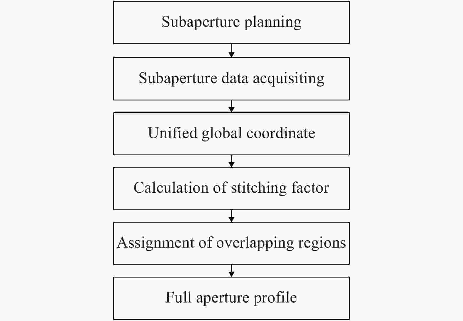
图 1 子孔径拼接流程图
Figure 1. Flow chart of subaperture stitching
在对待测平面镜进行拼接检测前,首先需要根据待检测元件参数完成其待测子孔径规划。子孔径规划时需要考虑待测元件尺寸与检测子孔径尺寸,要求检测中各待测子孔径可以实现对检测平面镜的全口径覆盖,同时各相邻子孔径间存在一定比例的重叠区域,通常重叠区域比例不低于待测镜面全口径尺寸的25%[21]。
在完成对待测平面镜的子孔径规划后,即可对各规划子孔径进行干涉检测数据采集。假设在子孔径规划时,共规划检测子孔径数目为
$ N $ 。此时,以$ N $ 号子孔径所在检测坐标系为基准坐标系,则对于第$ i $ 个子孔径,其检测结果在该基准坐标系内可以表示为:$$ {{{\textit{z}}}}_i'({{x}},{{y}}) = {{\textit{z}}_i}({{x}},{{y}}) + \sum\limits_{k = 1}^L {{F_{ik}}{f_k}({{x}},{{y}})} $$ (1) 式中:
${z_i}({{x}},{{y}})$ 为第$ i $ 个子孔径对应的干涉检测结果;$ {F_{ik}} $ 为第$ i $ 个子孔径中各检测调整误差项所对应的调整系数;${f_k}({{x}},{{y}})$ 为子孔径检测调整误差项。对于光学平面镜拼接检测,共有三项调整项,分别如公式(2)所示:$$ \left\{ {\begin{array}{*{20}{c}} {{F_{i1}} = x} \\ {{F_{i2}} = y} \\ {{F_{i3}} = 1} \end{array}} \right. $$ (2) 在球面镜与非球面拼接时,可以直接对上述调整误差项进行对应扩展。利用全局优化最小二乘拟合方法,各子孔径相对于基准子孔径的调整系数可以通过公式(3)获得:
$$ \begin{split} \min =& \sum\limits_{i = 1...{{N}}} {\sum\limits_{j = 1...N}^{j \cap i} {{{(({{\textit{z}}_i}({{x}},{{y}}) + \sum\limits_{k = 1}^L {{F_{ik}}{f_k}({{x}},{{y}})} ) - ({{\textit{z}}_j}({{x}},{{y}}) +}}}}\\ &{{{{\sum\limits_{k = 1}^L {{F_{jk}}{f_k}({{x}},{{y}})} )^2}}} }\\[-15pt] \end{split} $$ (3) 其中公式(3)可以写为矩阵的形式:
$$ P = Q \cdot R $$ (4) 矩阵
$ P,Q,R $ 的行与列分别对应为$(({{N}} - 1) \cdot {{L}}) \times 1$ ,$(({{N}} - 1) \cdot {{L}}) \times (({{N}} - 1) \cdot {{L}})$ ,$(({{N}} - 1) \cdot {{L}}) \times 1$ ,则公式(4)中的矩阵$ P,Q,R $ 可以具体写为如下形式:$$ {P_{ij}}[{{k}}] = \sum\limits_{i \cap j} {{f_{ik}}({{x}},{{y}})({{{Z}}_i}({{x}},{{y}}) - {{{Z}}_j}({{x}},{{y}}))} $$ (5) $$ P\left\{ {i,1} \right\} = \sum\limits_{j = 1}^N {{p_{ij}}} $$ (6) $$ {{{Q}}_{ij}}({{m}},{{n}}) = \left\{ {\begin{array}{*{20}{l}} {\displaystyle\sum\limits_{i \cap j} {{f_{im}}({{x}},{{y}}){f_{jm}}({{x}},{{y}})\;\;\;\;\;\;i \ne j} } \\ { - \displaystyle\sum\limits_{k = 1,…,N}^{k \ne i} {\sum\limits_{i \cap k} {{f_{im}}{{({{x}},{{y}})}_{jm}}f({{x}},{{y}})\;\;\;\;\;\;i = j } } } \end{array}} \right. $$ (7) $$ Q\left\{ {i,j} \right\} = {Q_{ij}} $$ (8) $$ {R_i}[{{k}}] = {F_{ik}} $$ (9) $$ R\left\{ {i,1} \right\} = {R_i} $$ (10) 由公式(4)~(10)即可求解得出各子孔径相对基准子孔径坐标系的拼接调整项系数,利用上述调整系统,将各子孔径检测数据校正到全局基准坐标系中,即可获得待测平面镜的全口径拼接结果。在传统拼接算法中,对于各相邻子孔径间重叠区域的相位值,采用取各个重叠子孔径的平均值[21],即:
$$ w({x_j},{y_j}) = \frac{1}{m}\sum\limits_{i = 1}^m {{w_i}({x_j},{y_j})} $$ (11) 式中:点
$ ({x_j},{y_j}) $ 为m个子孔径重叠区域内的坐标点,在高精度镜面拼接检测时,这种取值方式通常会在全口径拼接结果中或残差结果中留下“拼痕”。为了在拼接结果或残差结果中消除拼痕,笔者提出了拼接因子用于重叠区域取值,对处于子孔径重叠区域的相位数据采取加权平滑算法。为了更简洁地描述上述方法,以两个子孔径为例解释算法,如图2所示。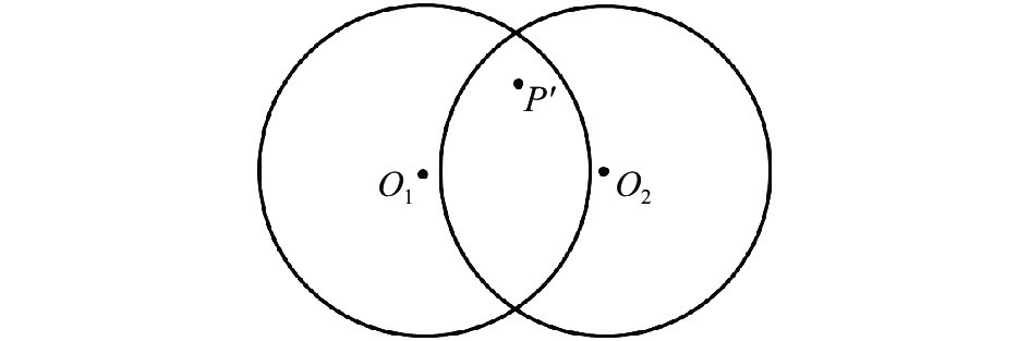
图 2 加权平滑拼接算法示意图
Figure 2. Schematic diagram of weighted smoothing stitching algorithm
图2中,点
$ {O_1} $ 及$ {O_2} $ 分别为两个相邻检测子孔径的圆心,点$P^{'}$ 为子孔径重叠区域内任意一点。假设在干涉检测中,靠近圆心点处的检测数据可信度更高,则基于拉格朗日插值思想,重叠区域内任意一检测点$P^{'}$ ,其相位值可以写为公式(12)的形式:$$ {\textit{z}} = {{\textit{z}}_1} \cdot \frac{{\left\| {{X_{P^{'}}} - {X_{O2}}} \right\|}}{{\left\| {{X_{O1}} - {X_{O2}}} \right\|}} + {{\textit{z}}_2} \cdot \frac{{\left\| {{X_{P^{'}}} - {X_{O1}}} \right\|}}{{\left\| {{X_{O2}} - {X_{O1}}} \right\|}} $$ (12) 式中:
$ \left\| { \cdot \cdot \cdot } \right\| $ 为二阶范数;$ {{\textit{z}}_1} $ 与$ {{\textit{z}}_2} $ 为相邻子孔径1与子孔径2在点P'处的干涉检测结果;${X_{P^{'}}}$ ,$ {X_{O1}} $ 与$ {X_{O2}} $ 分别为点$P'$ ,$ {O_1} $ 与$ {O_2} $ 所对应的向量表示,即$$ \left\{ {\begin{array}{*{20}{c}} {{X_{P^{'}}} = ({x_{P^{'}}},{y_{P^{'}}})} \\ {{X_{O1}} = ({x_{O1}},{y_{O1}})} \\ {{X_{O2}} = ({x_{O2}},{y_{O2}})} \end{array}} \right. $$ (13) 其中,
$({x_{P^{'}}},{y_{P^{'}}})$ ,$ ({x_{O1}},{y_{O1}}) $ 与$ ({x_{O2}},{y_{O2}}) $ 分别为点$P'$ ,$ {O_1} $ 与$ {O_2} $ 在基准坐标系内的坐标表示。此时,考虑一般情况,假设点
$P'$ 为N个子孔径重叠区域内一点,则其相位值为:$$ {\textit{z}} = sum(w\_k \cdot {\textit{z}}\_k) $$ (14) 式中:
$ {\textit{z}}\_k $ 为点$P'$ 在第k个子孔径中对应的干涉检测相位值;$ w\_k $ 为相应的权重因子,$$ w\_k = \frac{{\left\| {{X_{P^{'}}} - {X_{O1}}} \right\|...\left\| {{X_{P^{'}}} - {X_{O(k - 1)}}} \right\|\left\| {{X_{P^{'}}} - {X_{O(k + 1)}}} \right\|\left\| {{X_{P^{'}}} - {X_{ON}}} \right\|}}{{\left\| {{X_{Ok}} - {X_{O1}}} \right\|...\left\| {{X_{Ok}} - {X_{O(k - 1)}}} \right\|\left\| {{X_{Ok}} - {X_{O(k + 1)}}} \right\|\left\| {{X_{Ok}} - {X_{ON}}} \right\|}} $$ (15) $$ {\textit{z}} = sum(w\_k \cdot {\textit{z}}\_k)/sum(w\_k) $$ (16) -
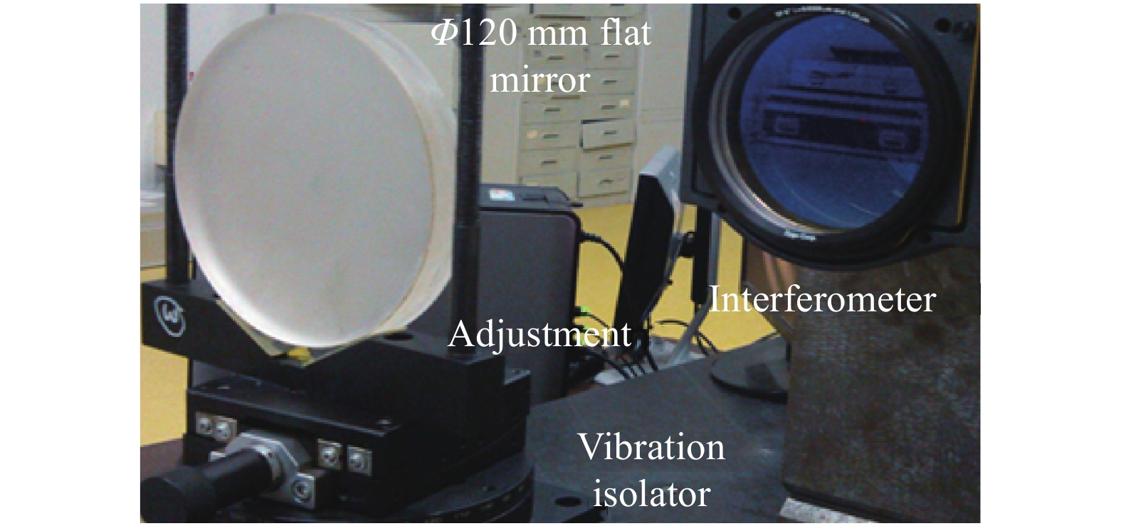
为了验证文中所述基于加权算法的平面镜子孔径拼接检测方法的可行性与拼接精度,笔者利用口径为150 mm干涉仪对120 mm平面镜进行了拼接检测,检测中,各子孔径是通过检测Mask获得的。具体检测光路如图3所示。
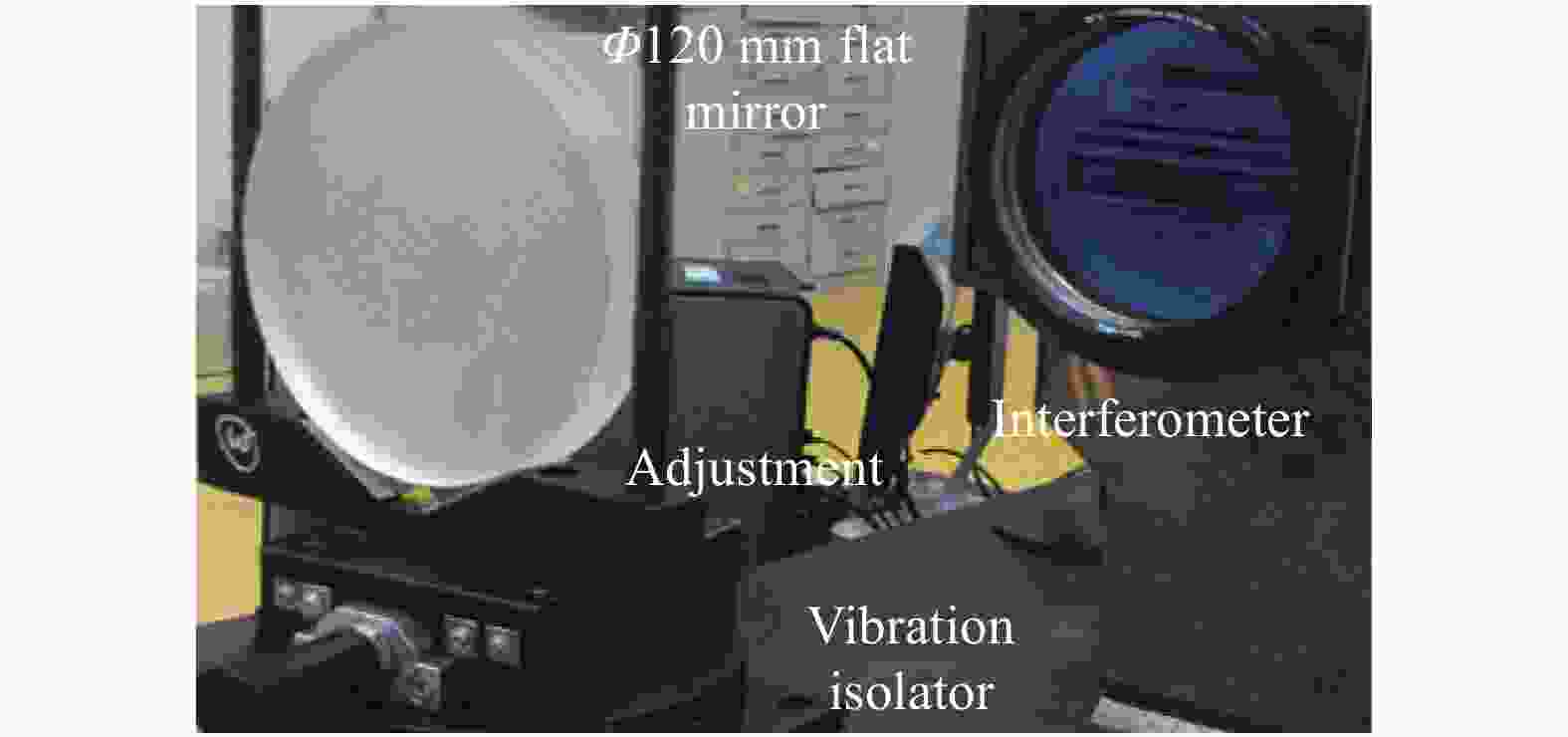
图 3 实验设备
Figure 3. Experimental setup
实验中,笔者所在课题组共完成了四个规划子孔径的干涉检测(上,下,左,右),各子孔径检测结果如图4所示。
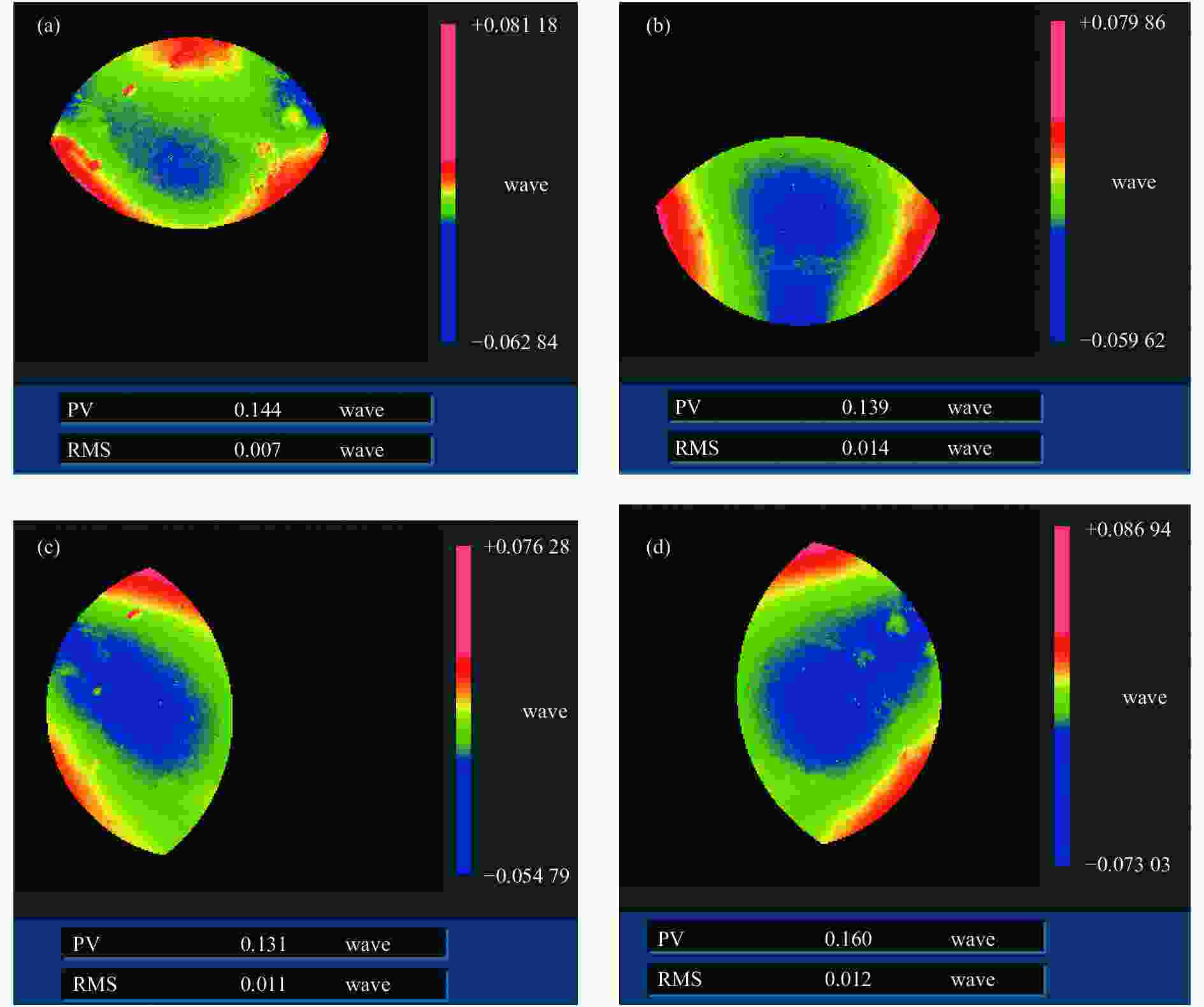
图 4 子孔径检测结果
Figure 4. Result of testing subapertures
为了更好地验证文中所述方法的拼接性能,同时对比其与传统拼接算法的拼接精度,分别基于文中所述算法与传统拼接算法[22]对各子孔径检测数据进行拼接,两组拼接结果分别如图5及图6所示。

图 5 加权算法拼接结果
Figure 5. Stitching result from weighting algorithm
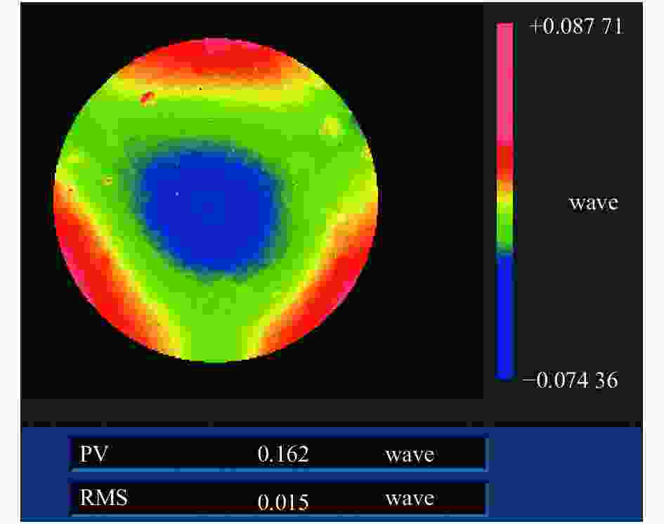
图 6 平均值算法拼接结果
Figure 6. Stitching result from average algorithm
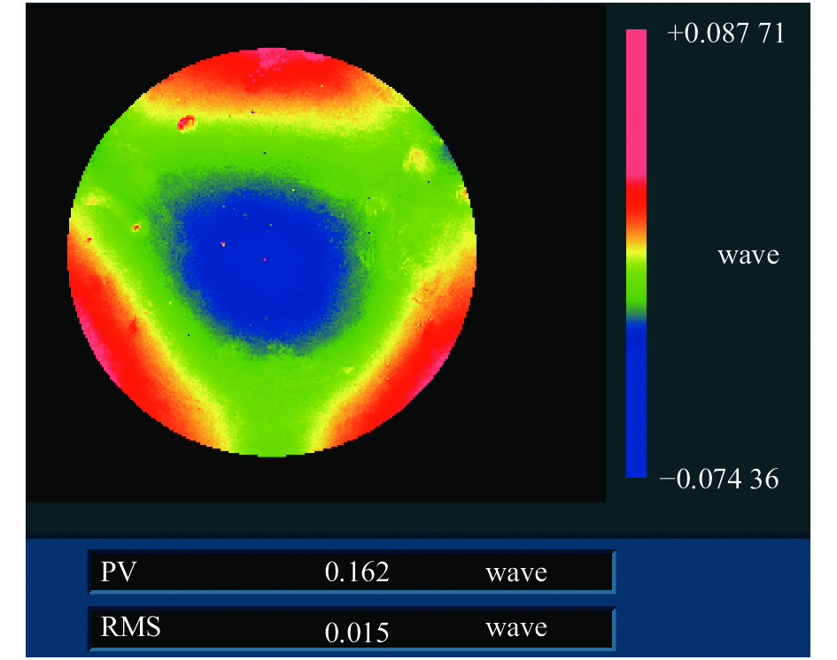
为了进一步对比两种算法的拼接精度,笔者同时对该平面镜进行了全口径检测,检测结果如图7所示。
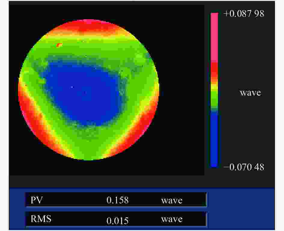
图 7 全口径检测结果
Figure 7. Full aperture testing result
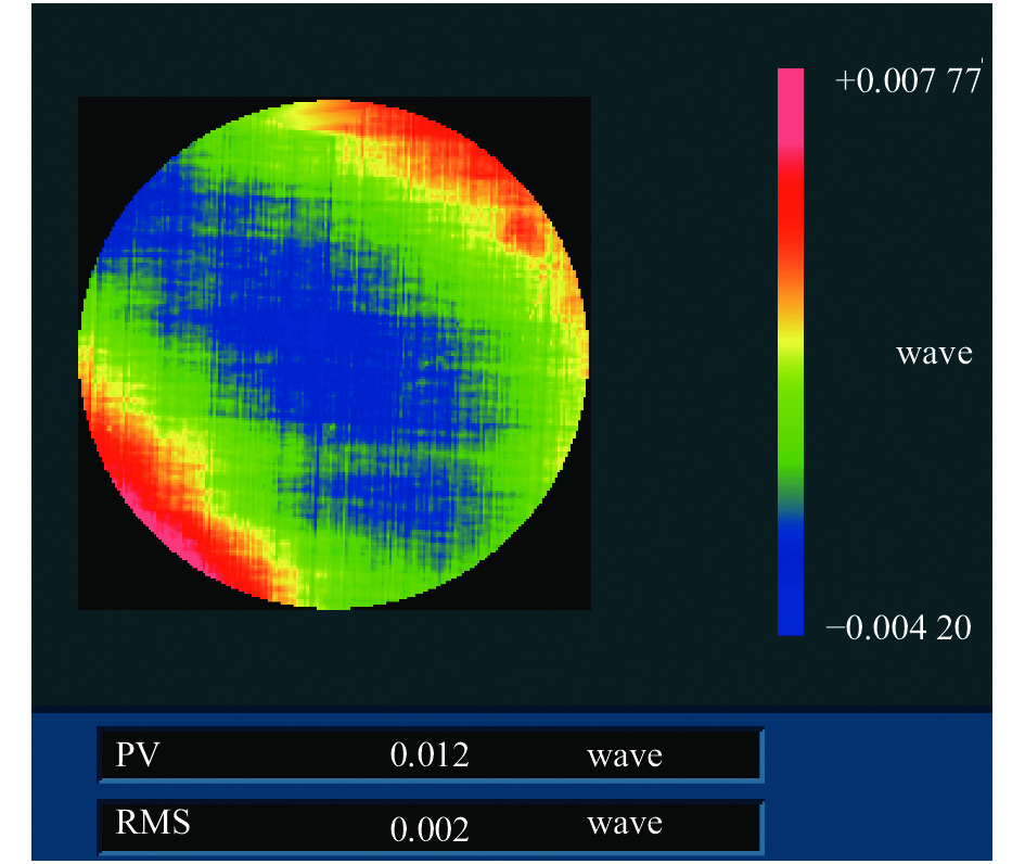
分别将两种算法所获得的拼接结果与全口径检测结果进行对比,得到拼接结果与全口径检测结果的残差图如图8及图9所示。
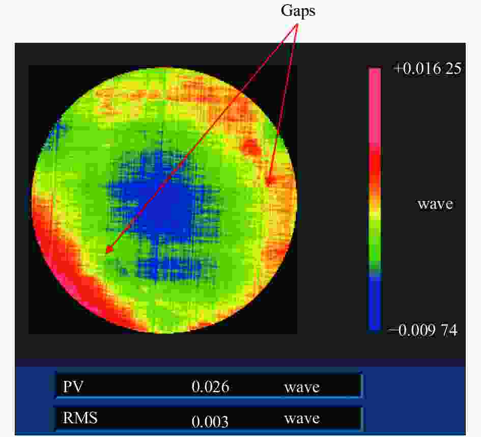
图 8 平均值算法残差图
Figure 8. Residual map from average algorithm

图 9 加权算法残差图
Figure 9. Residual map from weighting algorithm
由图8及图9可以看出,平均值算法中可以看到拼接痕迹,加权算法无明显拼接痕迹。同时加权算法中残差图的PV与RMS值分别为0.012λ与0.002λ,均优于平均值算法残差图中的对应结果。
-
文中提出了一种基于加权算法的平面镜子孔径拼接检测方法,引入重叠区域拼接因子的概念,对处于子孔径重叠区域的相位数据进行加权运算,同时基于上述拼接算法对Φ120 mm口径平面反射镜进行了拼接检测实验,并与传统重叠区域取平均值的拼接算法进行了对比分析。实验结果表明,文中所述算法得到的拼接结果光滑,无狭缝,拼接结果与全口径检测结果对比表明:二者PV与RMS值偏差分别为0.012λ与0.002λ,验证了拼接算法的可靠性和准确性。同时,文中算法具有良好的可扩展性,利用其进行球面及非球面、甚至自由曲面拼接测量时,可以对多项式的类型及多项式项数进行任意的扩展,具体利用文中算法进行球面镜、非球面镜及自由曲面镜的拼接结果将在后续文章中讨论。
Subaperture stitching testing to flat mirror based on weighting algorithm (Invited)
-
摘要: 为了解决大口径平面反射镜高精度检测问题,建立了一种基于全局优化的子孔径拼接检测数学模型,同时提出了一种拼接因子用于重叠区域取值。基于上述方法,结合工程实例,对一口径为120 mm的平面反射镜完成拼接检测,检测中共规划了四个待测子孔径,为了对比文中所述算法与传统最小二乘拟合拼接算法的拼接性能,分别利用两种算法完成了待测平面镜的面形重构。实验结果表明,两种算法所得拼接结果光滑、连续、无“拼痕”,同时分别将两种算法所得拼接结果与全口径检测结果进行了对比分析,从传统拼接算法残差图中可以看到明显的“拼痕”,而加权拼接方法得到的拼接结果光滑、连续,同时其残差图的PV与RMS值分别为0.012λ与0.002λ,小于传统算法残差图的PV与RMS值,验证了算法的可靠性与精度。Abstract: To solve the problem of high-precision testing of large-diameter plane mirrors, a mathematical model of subaperture stitching testing based on global optimization was established, and a stitching factor was proposed for overlapping area values. Based on the above method, combined with engineering examples, the stitching testing of a plane mirror was completed with a diameter of 120 mm, and four subapertures to be tested were planned. In order to compare the stitching performance of the algorithm described in this paper with the traditional least-squared fitting stitching algorithm, two algorithms were used to complete the surface reconstruction of the plane mirror to be measured. The experimental results show that the stitching results obtained by the two algorithms are smooth, continuous, no "stitch marks". At the same time, the results of the two algorithms are also compared with the full-aperture testing results. In this paper, obvious "stitch marks" can be seen in the residual map of the traditional splicing algorithm, and the stitching results obtained by the algorithm method in this paper are smooth and continuous, while the PV and RMS values of the residual graph are 0.012λ and 0.002λ, respectively, which are less than the PV and RMS values of the traditional algorithm residuals chart, which verifies the reliability and accuracy of the algorithm.
-
Key words:
- optical testing /
- interferometer /
- subaperture stitching /
- stitching factor
-
[1] Skidmore W. Thirty meter telescope detailed science case: 2015 [J]. RAA, 2015, 15(12): 1945-2140. [2] Ma D L. Recommended conceptual optical system design for China’s Large Optical-infrared Telescope (LOT) [J]. Opt Express, 2018, 28(1): 108-119. [3] Li H Y, Walker D, Yu G Y, et al. Modeling and validation of polishing tool influence functions for manufacturing segments for an extremely large telescope [J]. Appl Opt, 2013, 52(23): 5781-5787. [4] Li T, Liu Y, Sun Y Y, et al. Vectorial pupil optimization to compensate polarization distortion in immersion lithography system [J]. Opt Express, 2020, 28(4): 4412-4425. doi: 10.1364/OE.382051 [5] Vetter A, Kirner R, Opalevs D, et al. Printing sub-micron structures using Talbot mask-aligner lithography with a 193 nm CW laser light source [J]. Opt Express, 2018, 26(17): 22218-22233. doi: 10.1364/OE.26.022218 [6] Cheng Jimeng, Zhou Qinling, Chen Wei, et al. Detection of platinum particles in large diameter Nd: glass blank by high power laser radiation [J]. Infrared and Laser Engineering, 2017, 46(11): 1106001. (in Chinese) doi: 10.3788/IRLA201746.1106001 [7] Kim C J. Polynomial fit of interferograms [J]. Appl Opt, 1982, 21(24): 4521-4525. doi: 10.1364/AO.21.004521 [8] Tricard M, Dumas P, Forbes G. Subaperture approaches for asphere polishing and metrology [C]//Proc of SPIE, 2005, 5638: 284-299. [9] Supranowitz C, Fee C M, Murphy P. Asphere metrology using variable optical null technology [C]//Proc of SPIE, 2012, 8416: 841604. [10] Kulawiec A, Murphy P, Marco M D. Measurement of high-departure aspheres using subaperture stitching with the Variable Optical Null (VONTM)[C]//Proc of SPIE, 2010, 7655: 765512. [11] SU P, Burge J H, Parks R E. Application of maximum likelihood reconstruction of subaperture data for measurement of large flat mirrors [J]. Appl Opt, 2010, 49(1): 21-31. doi: 10.1364/AO.49.000021 [12] Yan L S, Luo W, Yan G J, et al. Subaperture stitching testing for fine flat mirrors with large apertures using an orthonormal polynomial fitting algorithm [J]. Opt and Lasers in Engineering, 2019: 120, 49-58. [13] Zhu Penghui, Tang Feng, Lu Yunjun, et al. Research on high accuracy sub-aperture stitching algorithm for flat optics [J]. Chinese Journal of Lasers, 2016, 43(11): 1104002. (in Chinese) doi: 10.3788/JCL201643.1104002 [14] Wang Xiaokun. Measurement of large off-axis convex asphere by systemic stitching testing method [J]. Chinese Optics, 2016, 9(1): 130-136. (in Chinese) doi: 10.3788/CO20160901.0130 [15] Zhang Haidong, Wang Xiaokun, Xue Donglin, et al. Surface testing method for ultra-large convex aspheric surfaces [J]. Chinese Optics, 2019, 12(5): 1147-1154. (in Chinese) doi: 10.3788/CO.20191205.1147 [16] Tian C, Yang Y Y, Wei T. Nonnull interferometer simulation for aspheric testing based on ray tracing [J]. Appl Opt, 2011, 50(20): 3559-3569. doi: 10.1364/AO.50.003559 [17] Zhang L, Liu D, Shi T, et al. Aspheric subaperture stitching based on system modeling [J]. Opt Express, 2015, 23(15): 19176-19188. doi: 10.1364/OE.23.019176 [18] Hou X, Wu F, Yang L. Experimental study on measurement of aspheric surface shape with complementary annular subaperture interferometric method [J]. Opt Express, 2007, 15(20): 12890-12899. doi: 10.1364/OE.15.012890 [19] Yang Z M, Du J U, Tian C, et al. Generalized shift-rotation absolute measurement method for high-numerical-aperture spherical surfaces with global optimized wavefront reconstruction algorithm [J]. Opt Express, 2017, 25(21): 26133-26147. [20] Yang Z M, Gao Z S, Zhu D, et al. Absolute ultra-precision measurement of high-numerical-aperture spherical surface by high-order shift-rotation method using Zernike polynomials [J]. Optics Communications, 2015, 355: 191-199. doi: 10.1016/j.optcom.2015.06.033 [21] 云宇. 基于子孔径拼接原理检测大口径光学元件技术的研究[D]. 长春理工大学, 2009, 3 Yun Yu. Detection of large aperture optical elements based on sub-aperture stitching principle[D]. Changchun: Changchun University of Science and Technology, 2009. (in Chinese) [22] Masashi O, Katsuyuki O, Jumpei T. Measurement of large plane surf ace shapes by connecting small-aperture interferograms [J]. Opt Eng, 1994, 33(20): 608-613. -

 点击查看大图

图(9)
计量
- 文章访问数: 454
- HTML全文浏览量: 168
- PDF下载量: 61
- 被引次数: 0


