


-
液晶偏振光栅(Liquid Crystal Polarization,LCPG)是一种衍射光学元件,不同偏振态光束入射LCPG后出射角度不同,将可调半波片(Adjustable Half Wave Plate, AHWP)与LCPG 串联,利用可调半波片控制入射光偏振态可实现光束出射方向的非机械偏转,将多片液晶偏振光栅正交串联组成正交级联偏振光栅(Orthogonal Cascaded Liquid Crystal Polarization Gratings,OC-LCPGSs),可实现光束大角度范围、小角度间隔的二维偏转(角度范围可达到±40°,角度间隔可达到1.25°)。相较于机械偏转器件,OC-LCPGSs具有尺寸小、质量轻、功耗低的优势;相较于液晶空间光调制器、光纤相控阵、光波导相控阵等非机械指向器件,具有偏转角度大的优势,其在激光通信、激光雷达、激光测距、激光测高等领域均具有广阔应用前景[1-5],这些领域均需要同时同向发射与接收激光,如能实现同口径收发则会缩小系统体积,降低对OC-LCPGSs口径的需求。
目前,参考文献[6-8]等给出了LCPG的理论、控制方法以及制备工艺,参考文献[5]介绍了光源经过单片LCPG后偏振态的变化以及OC-LCPGSs中光束方向可逆这一事实,并给出如何令接收光按原方向返回的方法,但其给出激光雷达结构仍为分口径结构,并未说明如何实现发射光与接收光共口径的方法,限制了其探测距离。
文中根据1/4波片(Quarter Wave Plate,QWP)、1/2波片(Half Wave Plate,HWP)以及LCPG理论推导出线偏振光源经过被动LCPG、LCPG层、OC-LCPGSs后偏振态变化,提出在OC-LCPGS前方加入PBS、1/4波片,在OC-LCPGS后加入可调半波片,组合后可实现发射光与接收光的分离问题,最后通过实物测试证明了理论与方法的准确性。
-
入射光经过1/4波片后,在快轴方向相位相较于慢轴可增加π/2,入射光经过1/2波片后,快轴方向相位相较于慢轴可增加π。可调半波片可实现入射光快轴方向与慢轴方向0~2π范围的相位差电控调制,经过标定,可使其只实现0与π两个相位差值的转换。
传输方向沿z轴、振动方向与y光轴呈45°夹角的线偏振光的可分解为两个频率相同、振幅相同、振动方向互相垂直的单色光波,可表示为:
$$ \begin{split} {E_{{{{x}}}}} = {a_x}\cos \left( {kz{{ - }}\omega t} \right) \\ {E_{{{{y}}}}} = {a_y}\cos \left( {kz{{ - }}\omega {\text{t}}} \right) \end{split} $$ (1) 当这一线偏振光透过快轴在y方向的1/4波片后,可表示为:
$$ \begin{gathered} {E_x} = {a_x}\cos \left( {kz{{ - }}\omega t} \right) \\ {E_y} = {a_y}\cos \left( {kz{{ - }}\omega t{\text{ + }}\dfrac{\pi }{2}} \right) \\ \end{gathered} $$ (2) 该出射光为左旋圆偏振光,左旋圆偏振光透过快轴在y方向的1/2波片后,可表示为:
$$ \begin{gathered} {E_x} = {a_x}\cos \left( {kz{{ - }}\omega t} \right) \\ {E_y} = {a_y}\cos \left( {kz{{ - }}\omega t{\text{ + }}\dfrac{{3\pi }}{2}} \right) \\ \end{gathered} $$ (3) 此时出射光为右旋圆偏振光(Right-handed Circularly Polarized Light, RCPL),令右旋圆偏振光或左旋圆偏振光(Left-handed Circularly Polarized Light, LCPL)经过可调半波片,当可调半波片的相位调制值为0时,偏振态没有变化;当可调半波片的相位调制值为π时,可实现圆偏振光左旋偏振态与右旋偏振态的转换。
-
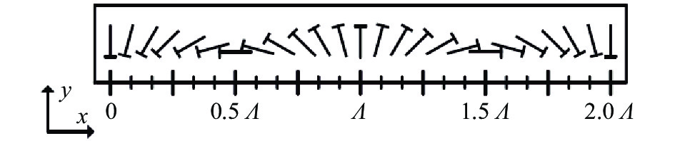
LCPG由平面单轴双折射液晶分子构成,液晶分子矢量随其位置呈周期性变化,其结构如图1 所示。

图 1 LCPG 的结构
Figure 1. Structure of LCPG
其两个偏振态的折射率:
$$ n\left( x \right) = \left[ {{\rm{sin}}\left( {{x \mathord{\left/ {\vphantom {x \varLambda }} \right. } \varLambda }} \right),{\text{ }}{\rm{cos}}\left( {{x \mathord{\left/ {\vphantom {x \varLambda }} \right. } \varLambda }} \right),{\text{ }}0} \right] $$ (4) 式中:Λ为光栅周期,液晶分子的相位φ=πx/Λ沿x轴呈周期变化[9-11]。
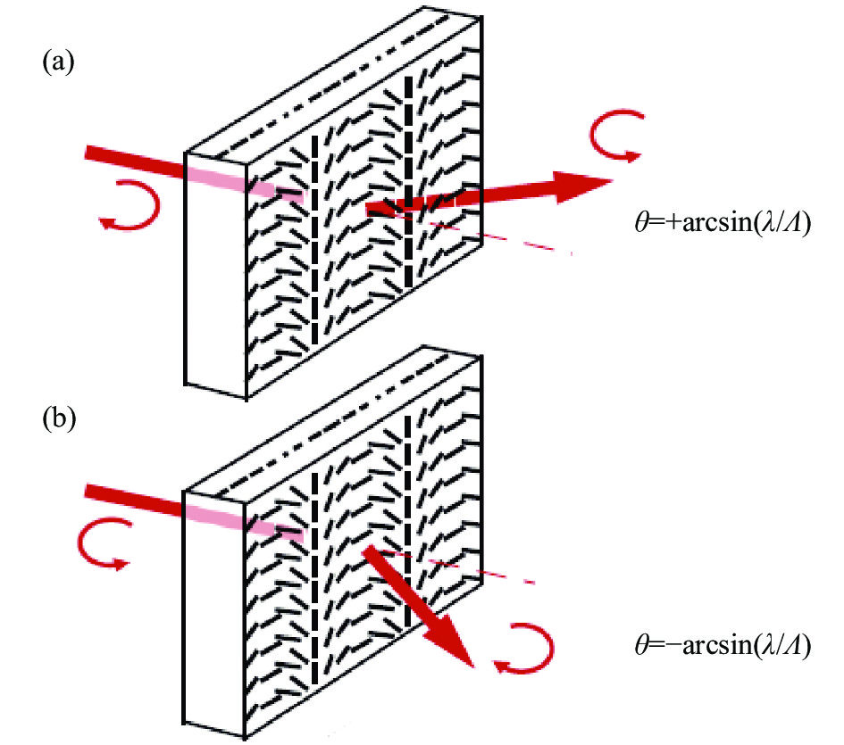
LCPG方面包含主动式LCPG与被动式LCPG两种,其中应用技术成熟的是被动式LCPG。光束经过被动式LCPG液晶光栅后,y方向的e光相位会产生周期性的变化,相同位相的电磁波能量主要集中在+1级或−1级,±1级的e光相较于o光会产生(2m+1)π (m=0, 1, 2, 3, ···)的延迟,改变出射光偏振态的同时也改变入射光出射角度,如图2所示。当入射光偏振态为左旋圆偏振光时,出射光束能量集中在+1级,偏振态为右旋圆偏振光;入射光偏振态为右旋圆偏振光时,出射光束能量集中在−1级,偏振态为左旋圆偏振光;入射光束为线偏振光时,出射光可以分解成左旋圆偏振光和右旋圆偏振光。通过在被动LCPG前加入可调半波片来转换入射偏光左旋与右旋的状态,可实现出射光束在±1级角度(±θ°)的偏转,在不考虑衍射效率、材料吸收等能量衰减因素的情况下,LCPG对于偏振态的改变相当于1/2波片,入射光经过后偏振态发生左旋与右旋的互换。

图 2 被动LCPG 的衍射特性:(a)入射光为右旋圆偏振光;(b)入射光为左旋圆偏振光
Figure 2. Diffraction properties of passive LCPG: (a) Incident light is right-handed circular polarization; (b) Incident light is left-handed circular polarization
当相同偏振态的出射光以+θ °或−θ °反向入射LCPG后,由于光路是可逆的,光线会在0°出射角(即入射光的−1级或+1级方向),e光相较于o光会产生(2m±1)π (m=0, 1, 2, 3, ···)的延迟,旋转方向发生左旋与右旋的转换。
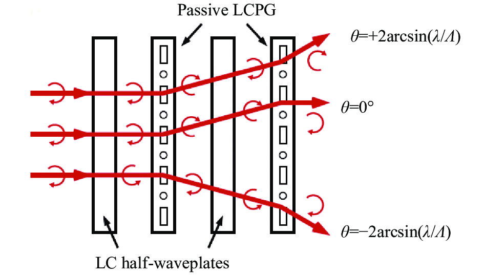
利用两个相同的被动LCPG与两个可调半波片串联组成一个“LCPG层”(如图3所示),通过调制可调半波片的相位可实现0°、−2θ °、+2θ °三个角度的偏转。

图 3 两个液晶可调半波片与两个LCPG组成的被动LCPG层
Figure 3. Passive LCPG layer with two LC-AHWPs and two LCPGs
不同偏振态入射光经过“LCPG层”后,实现不同角度的控制系数与偏振态变化如表1所示。
表 1 不同角度的控制系数与偏振态变化
Table 1. Control coefficient and polarization state change at different angles
Modulation angle/(°) Polarization state of incident light Phase delay of AHWP1 Polarization state after AHWP1 Polarization state after LCPG1 Phase delay of AHWP2 Polarization state after AHWP2 Polarization state after LCPG2 2θ RCPL 0 RCPL LCPL π RCPL LCPL 0 0 RCPL LCPL 0 LCPL RCPL −2θ π LCPL RCPL π LCPL RCPL 2θ LCPL π RCPL LCPL π RCPL LCPL 0 0 LCPL RCPL 0 RCPL LCPL −2 θ 0 LCPL RCPL π LCPL RCPL 当与出射光偏振态相同,传输方向相反的入射光逆向经过“LCPG层”,其偏振态变化如表2所示。
表 2 光路逆向条件下不同角度的控制系数与偏振态变化
Table 2. Control coefficient and polarization state change at different angles reverse light path
Modulation angle/(°) Polarization state before LCPG2 Polarization state before AHWP2 Phase delay of AHWP2 Polarization state before LCPG1 Polarization state before AHWP1 Phase delay of AHWP1 Polarization state before AHWP1 2θ RCPL LCPL π RCPL LCPL 0 LCPL 0 LCPL RCPL 0 RCPL LCPL 0 LCPL −2θ LCPL RCPL π LCPL RCPL π LCPL 2θ RCPL LCPL π RCPL LCPL π RCPL 0 RCPL LCPL 0 LCPL RCPL 0 RCPL −2θ LCPL RCPL π LCPL RCPL 0 RCPL 从表2中可以看出,在逆入射情况下,LCPG层中两个LCPG前,入射光偏振旋转方向与正入射情况下两个LCPG后相同。根据以上单片LCPG的分析结果,光束逆向入射情况下,光路方向与正入射方向重合,即光束传输方向可逆。
-
OC-LCPGs是将多层LCPG层串联组合,每层LCPG层实现一个固定角度的偏转,多层LCPG组合可实现大角度范围的偏转,组合形式包含二值式、类二值式与三值式,其中最常用的是二值式。
按照参考文献[7],二值式组合实现大角度偏转方法为第一层决定角度间隔,以后每一层的衍射角都是上一层衍射角的二倍(例如:1.25°、2.5°、5.0°、10.0°、20.0°),对于一个N层的OC-LCPGs,理论上共可以控制2
N+1个角度,为了实现1.25°间隔、±40°范围的角度偏转控制,共需要五层LCPG(2×40°/1.25°=64, 2N+1=64,N=5),为了实现二维的光束偏转,在正交方向需要同样的五层LCPG。 在正交方向设置同样的五层LCPG层,即正交级联,可实现光束的二维偏转。例如:为实现(22.5°,−16.25°)的光束偏转,弧矢方向(Sagittal Direction, SD)每一层LCPG中可调半波片的控制方式为:
$$ \begin{split} & 0 \times {1.25^ \circ } + 1 \times {2.5^ \circ } + 0 \times {5.0^ \circ } + 0 \times {10^ \circ } + 1 \times {20^ \circ } = \\ & \left( {{{0.625}^ \circ } - {{0.625}^ \circ }} \right) + \left( {{{1.25}^ \circ } + {{1.25}^ \circ }} \right) + \left( {{{2.5}^ \circ } - {{2.5}^ \circ }} \right) + \\ & \left( {{{5.0}^ \circ } - {{5.0}^ \circ }} \right) + \left( {{{10}^ \circ } + {{10}^ \circ }} \right) = {22.5^ \circ } \end{split} $$ 子午方向(Meridian Direction, MD)每一层LCPG中可调半波片的控制方式为:
$$ \begin{split} & - 1 \times {1.25^ \circ } + 0 \times {2.5^ \circ } - 1 \times {5.0^ \circ } - 1 \times {10^ \circ } + 0 \times {20^ \circ } =\\ & \left( { - {{0.625^ \circ } } - {{0.625^ \circ } }} \right) + \left( {{{1.25^ \circ }} - {{1.25^ \circ }}} \right) + \left( { - {{2.5^ \circ }} - {{2.5^ \circ }}} \right) + \\ & \left( { - {{5.0^ \circ } } - {{5.0^ \circ } }} \right) + \left( {{{10^ \circ } } - {{10^ \circ } }} \right) = {{ - }}{16.25^ \circ } \end{split} $$ 具体到每一层中可调半波片的控制参数如表3所示。
表 3 每一层中可调半波片的控制参数
Table 3. Control parameters of AHWP in each layer
Realization angle 0°(MD 1.25° layer) −1.25°(SD 1.25° layer) Wave plate serial number 0.625° 0.625° 0.625° 0.625° Control coefficient 0 0 1 1 Realization angle 2.5°(MD 2.5° layer) 2.5°(SD 2.5° layer) Wave plate serial number 1.25° 1.25° 1.25° 1.25° Control coefficient 0 1 0 0 Realization angle 0°(MD 5.0° layer) −5°(SD 5.0° layer) Wave plate serial number 2.5° 2.5° 2.5° 2.5° Control coefficient 0 0 0 1 Realization angle 0°(MD 10.0° layer) −10°(SD 10.0° layer) Wave plate serial number 5.0° 5.0° 5.0° 5.0° Control coefficient 0 0 1 1 Realization angle 20°(MD 20.0° layer) 0°(SD 20.0° layer) Wave plate serial number 10.0° 10.0° 10.0° 10.0° Control coefficient 0 1 0 0 根据表1中偏振态与偏转角度关系以及实际偏转角度,可得透过每个元件后偏振态变化如表4所示。
将这一出射光以相同偏振态逆向入射OC-LCPGS,其偏振态变化如表5所示。
由表5可见,光束逆向经过OC-LCPGS后,偏振态左右旋转方向相反。
表 4 正交级联液晶偏振光栅每个元件前、后偏振态
Table 4. Polarization states before and after each element of OC-LCPGS
Layer MD
1.25° layerSD
1.25° layerMD
2.5° layerSD
2.5° layerMD
5.0° layerSD
5.0° layerMD
10.0° layerSD
10.0° layerMD
20.0° layerSD
20.0° layerRealization angle/(°) 0 −1.25 2.5 2.5 0 −5 0 −10 20 0 Polarization state after layer RCPL RCPL LCPL LCPL LCPL RCPL RCPL RCPL LCPL LCPL -
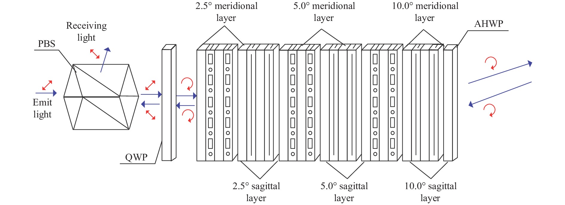
利用上述理论设计由偏振分光棱镜(PBS)、1/4波片、OC-LCPGs、末端可调半波片组成的收发分离结构,如图4所示。

图 4 采用OC-LCPGS的光束收发分离结构
Figure 4. Beam transceiver separation structure using OC-LCPGS
该结构中,通信发射光源为线偏振激光,振动方向与y方向呈45°,PBS的P光方向与光源振动方向相同,所以发射光源可以以较小的损耗通过级联LCPG,1/4波片将线偏振光转换成左旋圆偏振光,OC-LCPGs通过控制其中的可调半波片实现光束二维角度的控制,末端可调半波片实现发射通信光最终偏振态的控制,根据发射通信光经过正交OC-LCPGs后偏振态,令发射激光最终偏振态为右旋圆偏振光。
令发射与接收光偏振态相同,可实现光路逆向传输直到经过1/4波片前,逆向的右旋圆偏振光经过1/4波片会变成S光,S光在PBS内部反射,从而实现收发分离。
-
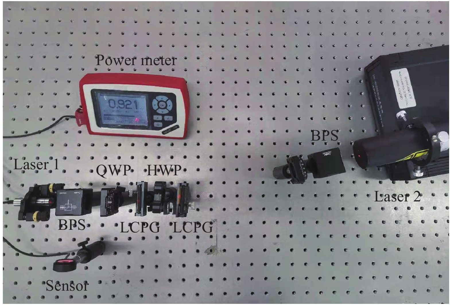
建立由两个同波长激光器、PBS、1/4波片、1/2波片(利用插拔1/2波片代替液晶可调半波片)、偏振光栅、光功率计组成的光束偏转结构如图5所示,实验器件的基本参数如表6所示。

图 5 OC-LCPGs收发分离结构验证实验图
Figure 5. Experimental diagram of OC-LCPGs receiving and transmitting separation structure verification
表 6 测试系统组成及指标
Table 6. Composition and index of test system
Component Parameter Value Laser 1 Wavelength/nm 630 Optical power/mW 3.20 Laser 2 Wavelength/nm 630 Optical power/mW 1.50 PBS Transmittance P:96%;
S:94%QWP Transmittance 96% HWP Transmittance 96% Grating Linear density of grating 1/lp·mm−1 159 Linear density of grating 2/lp·mm−1 159 Linear density of grating 3/lp·mm−1 286 Linear density of grating 4/lp·mm−1 286 Transmittance As shown in Fig.6 Thickness/mm 0.45±0.04 Material D263 令激光器1的光依次通过BPS、1/4波片、4片LCPG以及一片1/2波片后,光束方向为0°,测量光束偏振态为右旋圆偏振光,光功率为2.61 mW,可以确认被测光束是各个光栅主级次衍射光,不是次要级次的杂光。
利用激光器2、 BPS与1/4波片构成右旋圆偏振光模拟接收光源,令其反向通过系统,在BPS的透射方向与反射光方向分别设置光功率计,观察发现,光束虽然在经过每片LCPG后能量均会分散,但主级次能量与入射光同轴方向相反,BPS的反射光方向主级次能量为1.22 mW,透射方向主级次能量约为10 μW,可见主要能量集中在反射方向。
利用以上方法实现发射端不同调制角度,移动模拟接收光源多次测量得到的BPS的S光方向与P光方向光透过率如表7所示。
表 7 不同调制角度下透过率
Table 7. Transmittance at different modulation angles
Main order angle/(°) Transmittance of 1st measurement of S light Transmittance of 2nd measurement of S light Transmittance of 3rd measurement of S light Average transmittance of S light Average transmittance of P light 0 81% 82% 81% 81% <1% 10 61% 61% 61% 61% <1% −10 61% 61% 61% 61% <1% 20 52% 50% 53% 52% <1% −20 50% 50% 51% 50% <1% 30 41% 39% 40% 40% <1% −30 36% 37% 36% 36% <1% 由表7中的数据可见:随着偏转角度增大,接收光主级次能量减小,但主级次光均从PBS的S方向反射,证明发射光与接收光可成功分离。
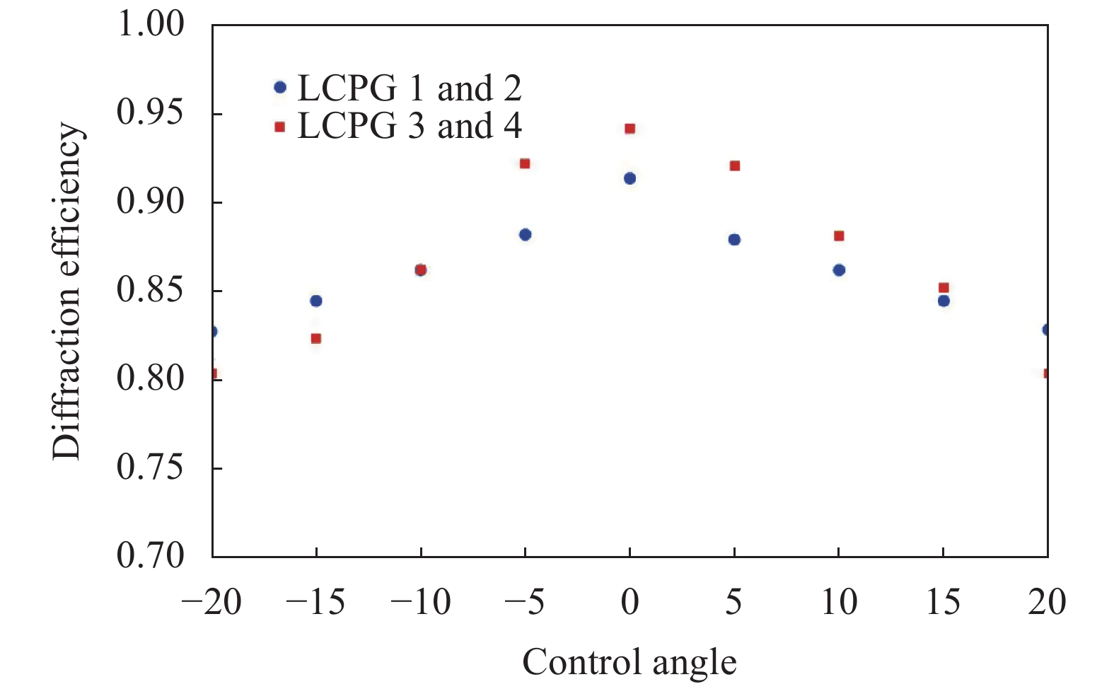
分析光束光功率透过率低的主要原因为实验采用的LCPG设计角度为0°,衍射效率随着入射角度增大而增大(实验中不同出射角度的液晶偏振光栅入射角度如表5所示,采用的两种液晶偏振光栅不同角度下的实测衍射效率如图6所示)。同时,不同入射角下的1/2波片产生的相位延迟量也不一致,导致入射液晶偏振光栅的相位不为π,进而进一步降低衍射效率。
表 5 逆入射情况下正交级联偏振光栅每个元件前、后偏振态
Table 5. Polarization states before and after each element of OC-LCPGS under the condition of reverse incidence
Layer SD
20.0° layerMD
20.0° layerSD
10.0° layerMD
10.0° layerSD
5.0° layerMD
5.0° layerSD
2.5° layerMD
2.5° layerSD
1.25° layerMD
1.25° layerRealization angle/(°) 0 −20 10 0 5 0 −2.5 −2.5 1.25 0 Polarization state after layer LCPL RCPL RCPL RCPL RCPL LCPL LCPL LCPL RCPL LCPL 
图 6 LCPG不同角度下的衍射效率
Figure 6. Diffraction efficiency of different LCPG at different angles
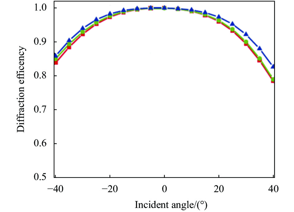
实验系统大角度偏转过程中光束入射后面LCPG的角度已经很大(如表8所示),所以整体透过率低。利用参考文献[11]中采用的带有镜面对称结构的液晶偏振光栅可以补偿斜入射的相位,在±30°的视场角范围内±1级的衍射效率均可以达到 90%以上(如图7所示),可以弥补结构器件的局限性。
表 8 不同调制角度下的入射角
Table 8. Incident angle at different modulation angles
Main order
angle/(°)Incident angle of
LCPG1/(°)Incident angle of
LCPG2/(°)Incident angle of
LCPG3/(°)Incident angle of
LCPG4/(°)0 0 5 0 10 10 0 5 10 0 −10 0 −5 −10 0 20 0 5 0 10 −20 0 5 0 −10 30 0 5 10 20 −30 0 −5 −10 20 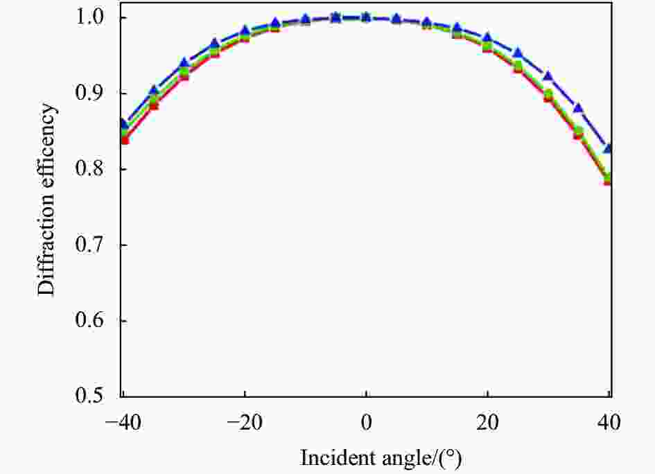
图 7 镜面对称结构的LCPG不同入射角下衍射效率
Figure 7. Diffraction efficiency of LCPG with mirror symmetry at different angles
-
文中提出在OC-LCPGS前方加入PBS、1/4波片,在OC-LCPGS后加入可调半波片,组合后可实现激光系统中发射光与接收光的分离问题,构建实验测试系统进行了测试,测试结果表明不同调制角度下均可实现发射光与接收光的分离,分析了实验系统透过率低的问题,分析结果表明采用带有镜面对称结构可以提高大偏转角度情况下的透过率。
Design of transceiver separation structure for orthogonal cascaded liquid crystal polarization gratings
-
摘要: 正交级联液晶偏振光栅可实现光束大范围偏转,在空间激光通信与激光雷达等领域具有广阔的应用前景,其大部分应用领域均需要同时发射激光与接收激光,如何解决发射光与接收光分离的问题尚未见报道。针对这一问题,文中根据1/4波片、1/2波片以及液晶偏振光栅理论推导了线偏振光源经过被动液晶偏振光栅层以及正交级联液晶偏振光栅后偏振态的变化,验证了出射光偏振态与光束偏转角度的可逆性。采用偏振分光棱镜、1/4波片、1/2波片、正交级联液晶偏振光栅等器件设计了一种可实现发射光与接收光偏转与分离的光学结构,构建了测试系统,最后通过测试结果证明了理论的正确性与结构的适用性。Abstract: Orthogonal cascaded liquid crystal polarization grating can realize optical beam large angle-scale deflection, and has broad application prospects in the fields of space laser communication and LiDAR. It need to emit and receive laser at the same time in most application fields, but how to solve the problem of separating emitted light from received light has not been reported. To solve this problem, change of polarization state of outgoing polarization light source after passing through passive liquid crystal polarization grating layer and orthogonal cascade liquid crystal polarization grating was deduced based on the theories of 1/4 wave plate, 1/2 wave plate and liquid crystal deflection grating, the reversibility of the polarization state of the outgoing light and the beam deflection angle was verified. An optical structure which could realize the deflection and separation of transmitted beam and received beam was designed using polarization splitting prism, 1/4 wave plate, 1/2 wave plate and orthogonal cascade liquid crystal polarization grating. A test system was constructed, the test results prove the correctness of the theory and the applicability of the optical structure finally.
-
图 2 被动LCPG 的衍射特性:(a)入射光为右旋圆偏振光;(b)入射光为左旋圆偏振光
Figure 2. Diffraction properties of passive LCPG: (a) Incident light is right-handed circular polarization; (b) Incident light is left-handed circular polarization
图 3 两个液晶可调半波片与两个LCPG组成的被动LCPG层
Figure 3. Passive LCPG layer with two LC-AHWPs and two LCPGs
图 4 采用OC-LCPGS的光束收发分离结构
Figure 4. Beam transceiver separation structure using OC-LCPGS
图 5 OC-LCPGs收发分离结构验证实验图
Figure 5. Experimental diagram of OC-LCPGs receiving and transmitting separation structure verification
图 6 LCPG不同角度下的衍射效率
Figure 6. Diffraction efficiency of different LCPG at different angles
图 7 镜面对称结构的LCPG不同入射角下衍射效率
Figure 7. Diffraction efficiency of LCPG with mirror symmetry at different angles
表 1 不同角度的控制系数与偏振态变化
Table 1. Control coefficient and polarization state change at different angles
Modulation angle/(°) Polarization state of incident light Phase delay of AHWP1 Polarization state after AHWP1 Polarization state after LCPG1 Phase delay of AHWP2 Polarization state after AHWP2 Polarization state after LCPG2 2θ RCPL 0 RCPL LCPL π RCPL LCPL 0 0 RCPL LCPL 0 LCPL RCPL −2θ π LCPL RCPL π LCPL RCPL 2θ LCPL π RCPL LCPL π RCPL LCPL 0 0 LCPL RCPL 0 RCPL LCPL −2 θ 0 LCPL RCPL π LCPL RCPL  下载: 导出CSV
表 2 光路逆向条件下不同角度的控制系数与偏振态变化
Table 2. Control coefficient and polarization state change at different angles reverse light path
Modulation angle/(°) Polarization state before LCPG2 Polarization state before AHWP2 Phase delay of AHWP2 Polarization state before LCPG1 Polarization state before AHWP1 Phase delay of AHWP1 Polarization state before AHWP1 2θ RCPL LCPL π RCPL LCPL 0 LCPL 0 LCPL RCPL 0 RCPL LCPL 0 LCPL −2θ LCPL RCPL π LCPL RCPL π LCPL 2θ RCPL LCPL π RCPL LCPL π RCPL 0 RCPL LCPL 0 LCPL RCPL 0 RCPL −2θ LCPL RCPL π LCPL RCPL 0 RCPL
下载: 导出CSV
表 3 每一层中可调半波片的控制参数
Table 3. Control parameters of AHWP in each layer
Realization angle 0°(MD 1.25° layer) −1.25°(SD 1.25° layer) Wave plate serial number 0.625° 0.625° 0.625° 0.625° Control coefficient 0 0 1 1 Realization angle 2.5°(MD 2.5° layer) 2.5°(SD 2.5° layer) Wave plate serial number 1.25° 1.25° 1.25° 1.25° Control coefficient 0 1 0 0 Realization angle 0°(MD 5.0° layer) −5°(SD 5.0° layer) Wave plate serial number 2.5° 2.5° 2.5° 2.5° Control coefficient 0 0 0 1 Realization angle 0°(MD 10.0° layer) −10°(SD 10.0° layer) Wave plate serial number 5.0° 5.0° 5.0° 5.0° Control coefficient 0 0 1 1 Realization angle 20°(MD 20.0° layer) 0°(SD 20.0° layer) Wave plate serial number 10.0° 10.0° 10.0° 10.0° Control coefficient 0 1 0 0
下载: 导出CSV
表 4 正交级联液晶偏振光栅每个元件前、后偏振态
Table 4. Polarization states before and after each element of OC-LCPGS
Layer MD
1.25° layerSD
1.25° layerMD
2.5° layerSD
2.5° layerMD
5.0° layerSD
5.0° layerMD
10.0° layerSD
10.0° layerMD
20.0° layerSD
20.0° layerRealization angle/(°) 0 −1.25 2.5 2.5 0 −5 0 −10 20 0 Polarization state after layer RCPL RCPL LCPL LCPL LCPL RCPL RCPL RCPL LCPL LCPL
下载: 导出CSV
表 6 测试系统组成及指标
Table 6. Composition and index of test system
Component Parameter Value Laser 1 Wavelength/nm 630 Optical power/mW 3.20 Laser 2 Wavelength/nm 630 Optical power/mW 1.50 PBS Transmittance P:96%;
S:94%QWP Transmittance 96% HWP Transmittance 96% Grating Linear density of grating 1/lp·mm−1 159 Linear density of grating 2/lp·mm−1 159 Linear density of grating 3/lp·mm−1 286 Linear density of grating 4/lp·mm−1 286 Transmittance As shown in Fig.6 Thickness/mm 0.45±0.04 Material D263
下载: 导出CSV
表 7 不同调制角度下透过率
Table 7. Transmittance at different modulation angles
Main order angle/(°) Transmittance of 1st measurement of S light Transmittance of 2nd measurement of S light Transmittance of 3rd measurement of S light Average transmittance of S light Average transmittance of P light 0 81% 82% 81% 81% <1% 10 61% 61% 61% 61% <1% −10 61% 61% 61% 61% <1% 20 52% 50% 53% 52% <1% −20 50% 50% 51% 50% <1% 30 41% 39% 40% 40% <1% −30 36% 37% 36% 36% <1%
下载: 导出CSV
表 5 逆入射情况下正交级联偏振光栅每个元件前、后偏振态
Table 5. Polarization states before and after each element of OC-LCPGS under the condition of reverse incidence
Layer SD
20.0° layerMD
20.0° layerSD
10.0° layerMD
10.0° layerSD
5.0° layerMD
5.0° layerSD
2.5° layerMD
2.5° layerSD
1.25° layerMD
1.25° layerRealization angle/(°) 0 −20 10 0 5 0 −2.5 −2.5 1.25 0 Polarization state after layer LCPL RCPL RCPL RCPL RCPL LCPL LCPL LCPL RCPL LCPL
下载: 导出CSV
表 8 不同调制角度下的入射角
Table 8. Incident angle at different modulation angles
Main order
angle/(°)Incident angle of
LCPG1/(°)Incident angle of
LCPG2/(°)Incident angle of
LCPG3/(°)Incident angle of
LCPG4/(°)0 0 5 0 10 10 0 5 10 0 −10 0 −5 −10 0 20 0 5 0 10 −20 0 5 0 −10 30 0 5 10 20 −30 0 −5 −10 20
下载: 导出CSV
-
[1] Ma Yanxing, Wu Jian, Su Rongtao, et al. Review of optical phased array techniques [J]. Infrared and Laser Engineering, 2020, 49(10): 20201042. (in Chinese) [2] Wang Xiangru, Zhou Zhuangqi. Research progress of liquid crystal optical phased array in high power laser application[J].Infrared and Laser Enigeering, 2018, 47(1): 0103006. (in Chinese) [3] Sakamoto M, Nhan H T, Noda K, et al. Polarized beam steering using multiply-cascaded rotating polarization gratings [J]. Applied Optics, 2021, 60(7): 2061-2068. [4] Sakamoto M, Yamada K, Momosaki R, et al. High-efficiency aerial display using a liquid crystal polarization grating, a retroreflector array, and a right-angle prism [J]. Applied Optics, 2020, 59(14): 191-198. [5] Hoy C, Stockley J, Shane J, et al. Non-mechanical beam steering with polarization gratings: A review [J]. Crystals, 2021, 11(4): 1-21. [6] Kim J, Oh C, Escuti M J, et al. Wide-angle, non-mechanical beam steering using thin liquid crystal polarization gratings [C]//Proceedings of SPIE, 2008, 7093: 709302. [7] Kim J, Matthew N M, Steve S, et al. Demonstration of large-angle non-mechanical laser beam steering based on LC polymer polarization gratings [C]//Acquisition, Tracking, Pointing, and Laser Systems Technologies XXV, Proceedings of SPIE, 2011, 8052: 80520T. [8] Kim J, Miskiewicz M N, Serati S, et al. High efficiency quasi-ternary design for non-mechanical beam-steering utilizing polarization gratings [C]//Advanced Wave-front Control: Methods, Devices, and Applications VIII, Proceedings of SPIE, 2010, 7816: 78160G. [9] Zhao Xiangjie, Duan Jiazhu, Zhang Dayong, et al. Oblique incidence effect on steering efficiency of liquid crystal polarization gratings used for optical phased array beam steering amplification [J]. Optical Review, 2016, 23(5): 1-10. [10] 李松振. 液晶偏振光栅的设计及其光偏转特性研究[D], 长春: 中国科学院长春光学精密机械与物理研究所, 2019. Li Songzhen. Design of liquid crystal polarization grating and study of its beam deflection characteristics[D]. Changchun: Changchun Institute of Optics, Fine Mechanics and Physics, Chinese Academy of Sciences, 2019. (in Chinese) [11] Chen Wan, Yu Yang, Mu Quanquan. Super-broadband geometric phase devices based on circular polarization converter with mirror symmetry [J]. Applied Physics Letters, 2021, 119(10): 101103. -

 点击查看大图
计量
- 文章访问数: 420
- HTML全文浏览量: 140
- PDF下载量: 35
- 被引次数: 0


