


-
非球面光学元件凭借自身优良的光学特性,为光学设计人员提供了更多的设计自由度,应用场景越来越广阔,特别是在空间望远观测、航天遥感、激光核聚变、极紫外光刻等重大技术领域的发展和应用[1-2]。各种复杂面形的非球面元件需求呈现爆发式增加趋势,而高精度的面形检测技术则是保障非球面加工质量、保证光学系统正常工作的关键环节。
现有面形测量手段多种多样,其中非接触式坐标点扫描法通过高精度光学测头测得一系列离散的三维坐标点,理论上可以得到被测元件的任何几何参数,非常适合用于测量各类复杂面形的光学镜面[3-7]。但目前国内外仍没有非球面镜面形轮廓测量相应的标准和规范,量值的准确统一无法保证,面形测量仪器标准器的缺失也使仪器校准值很难完成溯源。
国外较具有代表性的非接触式坐标测量装置有:荷兰埃因霍芬理工大学开发的NANOMEFOS测量系统[8],在500 mm测量范围内,测量不确定度为30 nm;美国Taylor Hobson公司开发的LuphoScans测量系统[9],适用于测量直径2~420 mm的球面和非球面光学元件,测量精度为±50 nm。国内现有面形轮廓测量的精密仪器主要依赖于进口,以及部分高校实验室研制的实验样机。哈尔滨工业大学研制了圆柱坐标扫描测量系统[10],精度优于1 μm,但由于仅有两个运动自由度,被测面形受限;浙江大学提出的测量技术可用于测量非轴对称的曲面面形[11-12],但各运动轴误差会叠加在测头上,使系统整体精度受较大影响。
为使面形轮廓的测量结果满足计量特性需求:统一性、准确性、溯源性,文中针对轴对称非球面反射镜的轮廓测量,提出一种非接触式坐标扫描测量方法。该方法采用分离式计量框架配合多路共基准的激光干涉扫描系统,有效提高扫描测量精度至亚微米级且使测量值能够溯源到“米”定义。
-
为满足各类复杂光学镜面轮廓的测量需求,该测量方法应用通用性较强的坐标测量技术,通过非接触式光学测头对待测光学元件面形轮廓进行逐点扫描测量。扫描测量过程中,光学测头应始终沿非球面表面上任意待测曲线的等距线移动,角度始终保持与曲线上任意一点的法线方向保持平行。以非球面的子午截面曲线为例,图1为光学测头对凸/凹非球面的子午线扫描轨迹示意图。

图 1 光学测头法线跟踪轨迹示意图
Figure 1. Schematic diagram of the optical probe normal tracking trajectory
非球面子午截面曲线具有一定特殊性,曲线上各点的曲率半径均不相同,因此需利用被测点与图1中构造的几何关系求得光学测头实际位置。设子午面曲线上任一待测点为Pi(xi, yi),L为已知的光学测头长度,沿曲线过Pi(xi, yi)点的法线方向距离为L的点设为Ki,每一个待测点在扫描一侧均有唯一对应的Ki点,全部Ki离散点集合即为测头的实际运动轨迹。
已知通用的轴对称高次非球面曲线方程表达式为:
$$ {x}=\frac{C{y}^{2}}{1+\sqrt{1-(1+K){C}^{2}{y}^{2}}}+d{y}^{4}+e{y}^{6}+g{y}^{8}+\dots $$ (1) 式中:C=1/R0为非球面子午截面曲线顶点曲率,R0为曲线顶点的曲率半径;K=–e2为曲线常数,e2为曲线形状系数;d,e,g,···为系数。
曲线过任一Pi(xi,yi)点的法线方程为:
$$ {{y - }}{{{y}}_i} = - \frac{1}{{y'}}(x - {x_i}) $$ (2) 对公式(1)求导数可得:
$$ {{y}}' = \frac{1}{{f + 4a{y^3} + 6b{y^5} + 8c{y^7} + 10d{y^9} + ...}} $$ (3) $$ \begin{split} {{f}} = &\frac{{2Cy}}{{1 + \sqrt {1 - (1 + K){C^2}{y^2}} }} + \\& \frac{{(1 + K){C^3}{y^3}}}{{{{(1 - \sqrt {(1 + K){C^2}{y^2}} )}^2}\sqrt {1 - (1 + K)C{y^2}} }} \end{split} $$ (4) 曲线上过Pi(xi, yi)点的法线(或法线延长线)与X轴交点为Qi ,由公式(2)可知该点坐标Qi(yiy'+xi,0),此时法线与X轴夹角θi为:
$$ {\theta _{\text{i}}} = \arctan \frac{{\left| {{y_i}} \right|}}{{\left| {{x_i} - {y_i}y' - {{{x}}_{\text{i}}}} \right|}} = \arctan \left| {\frac{1}{{y'}}} \right| $$ (5) 扫描轨迹关于Y轴对称,当非球面镜面为凸镜面时,第一象限内扫描轨迹点Ki (xi+L·cosθi,yi+L·sinθi);当非球面面形为凹面镜时,第一象限内扫描轨迹点Ki (xi−L·cosθi,yi+L·sinθi)。即测量过程中,任一时刻光学测头的空间位置主要与被测面形尺寸及法线方向有关。理论上,当扫描装置X、Y方向有足够的运动空间,光学测头可转动角度大于等于90°时,即可对各类连续性轴对称非球面面形进行测量。
-
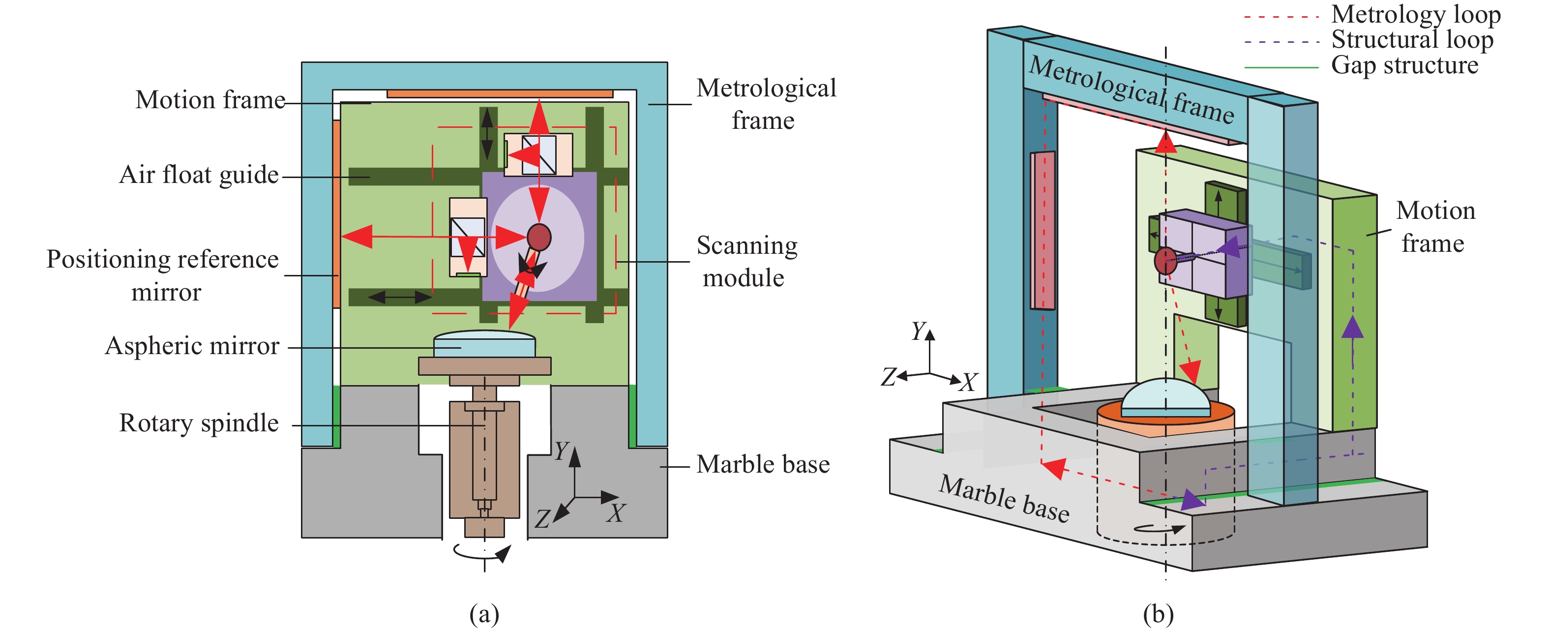
以传统的三坐标测量机扫描结构为例,三个运动轴共计21项运动误差,测量过程中的振动以及环境变化误差均有可能会耦合到扫描测头上,严重限制了坐标扫描测量系统的测量精度[13]。为避免运动机构造成的各项误差累积,提出一种运动回路与计量回路相互独立的分离式计量框架结构如图2所示。
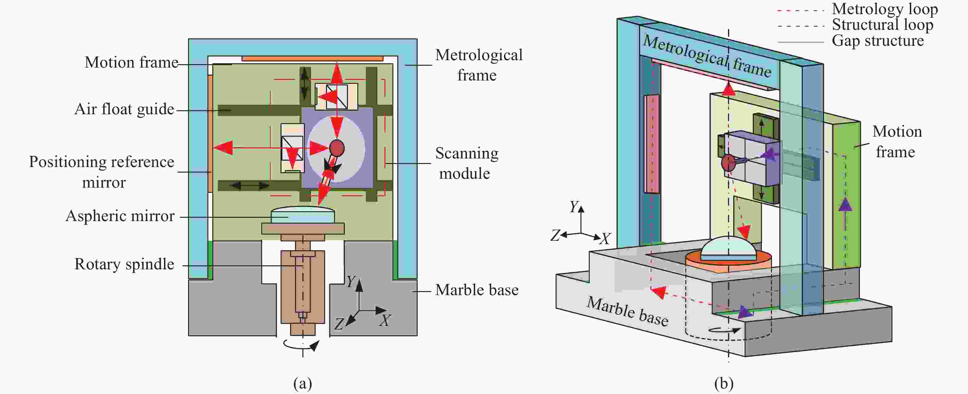
图 2 分离计量框架式坐标扫描装置示意图
Figure 2. Schematic diagram of coordinate scanning device with separate metrology frames
测量时,运动框架支撑跟踪扫描模块进行X、Y方向运动,配合工件台的回转运动保证镜面轮廓的完整扫描;计量框架上不承担任何运动机构负载,仅用于计量回路内干涉定位系统获取位移信息,实时确定跟踪扫描模块的空间位置以及被测点位信息。该分离式计量框架结构具有以下特性:(1)计量框架与运动框架相互独立,可以保证计量框架的相对稳定性。有效避免在测量过程中,扫描模块运动引起支撑框架内部发生形变、振动以及环境热变化等误差因素对测头造成影响,保证系统整体测量精度;(2)计量回路内应用激光干涉测量系统,能够实时高精度地获取扫描模块X、Y方向运动位移信息,保证测头运动轨迹的准确性,最大程度满足阿贝原则。
-
非接触坐标测量系统能对形状比较复杂的非球面元件进行三维测量,主要通过光学测头来拾取点位信号,因此测量系统的功能、效率、精度等均与测头密切相关。目前常见的各类非接触式扫描测头的特性参数[14-18]见表1。
表 1 各类非接触式扫描测头的特性参数
Table 1. Characteristic parameters of different non-contact scanning probes
Probe type Resolution Range Characteristics Differential confocal 10 nm (Vertical resolution) Micron-scale Must be matched with the actuator to
increase the range, and increased sources of errorsDispersion confocal 0.5 nm (Vertical resolution) Micron-scale White-light interference <0.1 nm (Vertical resolution) Micron-scale Multi-wavelength interference Sub-nanometer Millimeter-scale Large working distance Self-focused sensing 0.2 μm Millimeter-scale Large working distance but insufficient precision Laser triangulation 2 μm Millimeter-scale Scanning tunnel microscope 5 nm <1 nm Low scanning efficiency and only metal parts can be measured 对比发现,现有的光学测头量程大则精度较低;精度高则量程小,高精度测头常受其执行机构的运动精度影响使整体测量系统精度降低。因此,该测量方法采用测量精度较高的激光干涉测量,结合上文提出的分离式计量框架结构,可在获得较高测量精度的同时有效降低执行机构引入的各项运动误差。
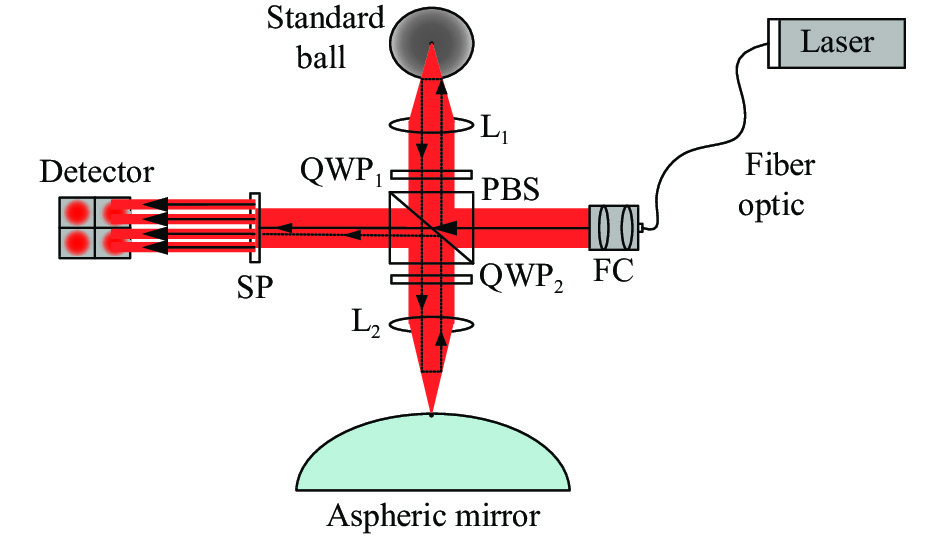
激光干涉测头原理如图3所示。光矢量与入射平面成45°夹角的线偏振光,经光纤传输至光纤准直器FC后垂直入射PBS,被分光成两束相互垂直的线偏振光。其中:(1)水平线偏振光穿透PBS照射至探测器作为干涉参考光;(2)垂直线偏振光经PBS折射至凸透镜L1,焦点汇聚于标准球圆心上原路返回至PBS,途中经过λ/4波片QWP1两次,使原本垂直的线偏振光变为水平偏振光,此时该路光束能够直接透过介质分束膜,再一次经过凸透镜L2,焦点汇聚于待测曲面的测量点上,光路二次返回PBS,经过两次λ/4波片QWP2恢复为垂直线偏振光,经PBS折射后,作为干涉测量光最终与干涉参考光汇合。重合后光束经分束镜SP等分为四路,照射至四通道光电探测器上得到相对位移信息。
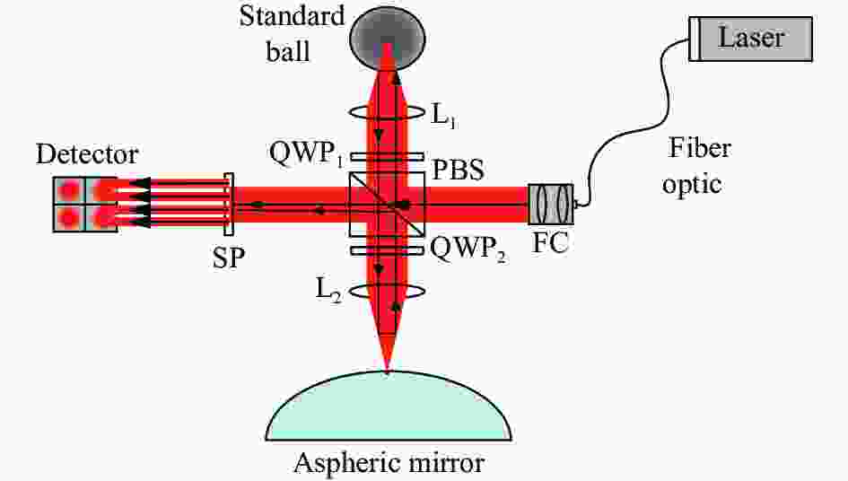
图 3 光学测头干涉原理示意图
Figure 3. Schematic diagram of optical probe interference principle
该干涉测头应用笔者课题组研制的集成阵列式波片的四象限干涉测量系统[19],适用于测量反射元件的相对位移。该系统应用NI-5734数字化适配器模块,能够同时对四通道的信号进行采集,采样率120 MHz,实际AD采集分辨率大于12.1位,静态分辨率优于1 nm,2 000 mm测量范围内,标准差为48.58 nm;针对非球面反射镜动态测量时,在30 μm的测量范围内,系统测量偏差在±3 nm之间,分辨率约为1 nm[20]。较传统的单频干涉系统集成度更高、光学测头的体积更小,能够起到增大光学测头旋转角度、减小测头对扫描执行机构的负载、提升测头的动态性能的作用,更有利于进行复杂面形轮廓的测量。
-
跟踪扫描模块作为干涉光学测头运动的执行机构,是测量系统的核心运动部件,负责对被测轴对称光学元件的面形轮廓进行扫描跟踪运动,其空间定位的准确性直接影响测量结果的正确性。为保证其运动轨迹的的准确性,提出一种运动执行机构与多路激光干涉共基准的空间定位方法,图4为跟踪扫描模块的空间定位与测量原理图。

图 4 跟踪扫描模块的空间定位与测量原理
Figure 4. Positioning and measuring principle of scanning mechanism
跟踪扫描模块内安装ϕ25 mm基准球作为跟踪扫描模块的运动基准,同时,该基准球还是模块内干涉定位系统和干涉测头共同的参考测量基准。其中:
(1)干涉定位系统由X、Y轴两套相对位置垂直的干涉系统组成,其原理均如图3所示,通过测量基准球与计量框架上定位参考镜M1、M2的相对位移变化量△X、△Y,确定参考基准球在XY平面内的实时空间坐标,即跟踪扫描模块运动的实时坐标信息;
(2)干涉测头始终围绕基准球做等距圆周转动,测得基准球与被测点的相对位移变化量△L后,结合基准球的空间位置与干涉测头转角即可确定该测量点的准确空间坐标。
跟踪扫描模块的运动基准与各干涉系统测量基准的统一,保证了扫描模块自身空间定位的准确性与运动精度,可以将测得的非球面面形信息直接溯源至光波长“米”定义上,为非球面镜面形轮廓测量量值统一和溯源提供一种有效的技术方案。
-
根据上述测量方法搭建非接触式扫描测量装置,如图5所示。为获得该测量方法的准确测量精度,避免转台转动带来的各项误差耦合至测量结果上,因此此次测量精度试验将固定待测镜,仅通过跟踪扫描模块运动对被测反射镜表面子午线进行坐标测量,并与镜面理论参考值进行比较。

图 5 非接触式扫描测量装置
Figure 5. Non-contact scanning measurement device
测试现场条件:实验室空调可控环境,环境温度20.05~20.16 ℃、环境相对湿度区间为[51.9%,52.3%]、气压区间为[1013.2 hPa, 1013.3 hPa]。
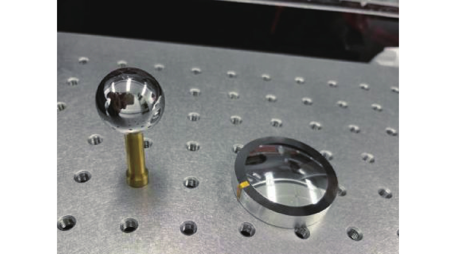
分别对ϕ25 mm标准球圆周及非球面镜(R0=45、K=−2,直径40 mm)的子午线进行扫描测量,被测反射镜实物图如图6所示。

图 6 被测反射镜实物图
Figure 6. Image of reflector under test
(1) ϕ25 mm标准球轮廓测量精度试验,测试起始位置为ϕ25 mm标准球圆周上顶点,此时测头转角为0°,垂直向下,对同一圆周连续不间断测量五次,沿X方向测量距离为10 mm,并将实测数据与标准球圆周参考值的差值作为测量的系统误差,实测数据如图7所示。

图 7 ϕ25 mm标准球测量误差
Figure 7. Measurement errors of ϕ25 mm standard ball
针对五次测量结果求得标准球测量标准差如图8所示,针对ϕ25 mm标准球沿顶点至半径10 mm镜面轮廓范围内圆周,测量误差小于0.2 μm,重复精度在65 nm以内,重复性较好。
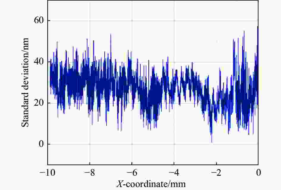
图 8 ϕ25 mm标准球测量标准差
Figure 8. Measurement standard deviation of ϕ25 mm standard ball
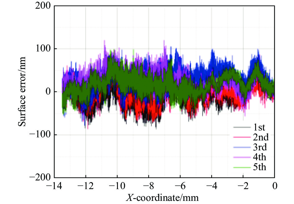
(2)非球面镜子午线轮廓测量精度试验,测试起始位置为非球面镜的子午线顶点,此时测头转角为初始0°,垂直向下,对同一子午线连续不间断测量五次,沿X方向测量距离为14 mm,并将实测数据与非球面镜母线的参考值的差值作为测量的系统误差,实测数据如图9所示。

图 9 非球面镜测量误差
Figure 9. Measurement errors of aspheric mirror
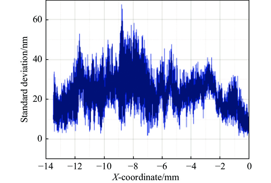
针对五次测量结果求得非球面镜测量标准差如图10所示,被测非球面反射镜径向14 mm的镜面轮廓进行测量,测量不确定度在0.2 μm内,重复精度在70 nm以内,重复性较好。

图 10 非球面镜测量标准差
Figure 10. Measurement standard deviation of aspheric mirror
通过对不同光学反射镜面的测量试验可知,应用高精度非接触式轴对称光学元件轮廓测量方法针对不同面形光学反射镜测量结果一致,独立计量框架结构使得测量结果稳定性较高,测量误差小于0.2 μm,重复精度在70 nm以内,测量精度达到亚微米级。
-
文中提出了一种高精度、可溯源的轴对称非球面反射镜轮廓测量方法,提高非球面轮廓测量精度至亚微米级。建立了适用于各类轴对称非球面面形轮廓扫描的数学模型;采用分离式计量框架结构,有效降低了扫描测量过程中运动模块对系统测量精度的影响;应用集成阵列式波片的四象限干涉测头,保证测量分辨率在1 nm左右,同时减小光学测头的体积,更有利于进行复杂面形的跟踪扫描运动;采用运动基准与各干涉系统测量基准统一的跟踪扫描模块,在提高扫描定位精度的同时保证了测量值能溯源到“米”定义上。最后,分别对标准球和非球面镜的不同面形轮廓进行测量试验,结果表明,应用该测量方法的测量误差小于0.2 μm,重复性精度为70 nm。为解决非球面镜面形轮廓高精度测量的量值统一和溯源问题提供了一种有效技术方案。
High-precision profile measurement method for axisymmetric aspheric mirror (invited)
-
摘要: 为实现轴对称非球面反射镜轮廓的高精度、可溯源测量,建立了非球面测量轨迹的数学模型,提出了一种基于独立计量回路的非接触式坐标扫描测量方法。该方法采用分离式计量框架结构,有效减少了跟踪扫描模块运动对测量精度的影响;测头采用集成阵列式波片的四象限干涉测量系统,保证测头精度的同时更有利于实现复杂面形轮廓的跟踪扫描运动;设计扫描执行机构与多路激光干涉系统共基准的运动模块,实时跟踪扫描运动机构的位置信息,提高测头空间定位精度并使其测量值能溯源到“米”定义。搭建测量装置测试该方法的准确测量精度,试验结果表明,测量误差小于0.2 μm,重复性精度为70 nm,测量精度达到亚微米级。Abstract: In order to achieve the goal of high-precision and traceable aspheric surface profile measurement, a mathematical model of the measurement trajectory is established for the surface profile measurement of axisymmetric aspheric mirrors, and a non-contact coordinate scanning measurement method with independent metrology loop is proposed. The method applies a separated metrology frame, which effectively reduces the influence of each motion module on the measurement accuracy of the system during the measurement process; the probe adopts a four-quadrant interferometry system with integrated array waveplates, which improves the dynamic performance of the probe and is more conducive to the measurement of complex aspheric surface shapes; the motion module with a common reference between the scanning actuator and the multiplexed laser interferometry system is designed to track the position information of the scanning motion mechanism in real time, which improves the accuracy of the scanning motion and enables the measurement of the surface shape. The scanning actuator is designed to track the position information of the scanning motion mechanism in real time to improve the accuracy of the probe motion and make its measurement value traceable to the definition of "meter". The measurement device is built and the surface profile of the standard sphere and aspheric mirror are measured separately. The test results show that the measurement error is less than 0.2 μm and the repeatability accuracy was 70 nm, and the system measurement accuracy reaches submicron level.
-
Key words:
- surface inspection /
- aspheric /
- non-contact measurement /
- interferometric probe
-
图 1 光学测头法线跟踪轨迹示意图
Figure 1. Schematic diagram of the optical probe normal tracking trajectory
图 2 分离计量框架式坐标扫描装置示意图
Figure 2. Schematic diagram of coordinate scanning device with separate metrology frames
图 4 跟踪扫描模块的空间定位与测量原理
Figure 4. Positioning and measuring principle of scanning mechanism
表 1 各类非接触式扫描测头的特性参数
Table 1. Characteristic parameters of different non-contact scanning probes
Probe type Resolution Range Characteristics Differential confocal 10 nm (Vertical resolution) Micron-scale Must be matched with the actuator to
increase the range, and increased sources of errorsDispersion confocal 0.5 nm (Vertical resolution) Micron-scale White-light interference <0.1 nm (Vertical resolution) Micron-scale Multi-wavelength interference Sub-nanometer Millimeter-scale Large working distance Self-focused sensing 0.2 μm Millimeter-scale Large working distance but insufficient precision Laser triangulation 2 μm Millimeter-scale Scanning tunnel microscope 5 nm <1 nm Low scanning efficiency and only metal parts can be measured  下载: 导出CSV
-
[1] Li Chijuan, Sun Changfeng, Xi Zhe, et al. Application of optical aspheric element [J]. Laser & Infrared, 2013, 43(3): 244-247. (in Chinese) doi: 10.3969/j.issn.1001-5078.2013.03.003 [2] Liang Zijian, Yang Yongying, Zhao Hongyang, et al. Advances in research and applications of optical aspheric surface metrology [J]. Chinese Optics, 2022, 15(2): 161-186. (in Chinese) doi: 10.37188/CO.2021-0143 [3] 贾立德. 光学非球面坐标测量关键技术研究[D]. 国防科学技术大学, 2008. Jia Lide. Study on key techniques of coordinate measurement for optical aspherics[D]. Changsha: National University of Defense Technology, 2008. (in Chinese) [4] Mathia T G, Pawlus P, Wieczorowski M. Recent trends in surface metrology [J]. Wear, 2011, 271(3): 494-508. [5] 侯茂盛. 大口径非球面表面形状测量关键技术研究[D]. 北京理工大学, 2015. Hou Maosheng. Study on key techniques of profile measurement for large aperture optical aspherics[D]. Beijing: Beijing Institute of Technoloty, 2015. (in Chinese) [6] Ping Shaodong, Fu Yunxia, Zhang Feng, et al. Study on measurement method of mirror reflection laser tracking interferometric length measurement [J]. Infrared and Laser Engineering, 2021, 50(12): 20210624. (in Chinese) [7] Wang Xiaokun. Measurement of large aspheric surface by stitching and coordinate measuring machine [J]. Infrared and Laser Engineering, 2014, 43(10): 3410-3415. (in Chinese) [8] Henselmans R. Non-contact measurement machine for freeform optics[D]. Eindhoven: Technische Universiteit Eindhoven, 2009. [9] Berger G, Petter J. Non-contact metrology of aspheric surfaces based on MWLI technology [C]//Proceedings of SPIE-International Society for Optics and Photonics, 2013, 8884: 88840V. [10] 朗治国. 基于超精密回转扫描的大口径非球面测量技术研究[D]. 哈尔滨工业大学, 2009. Lang Zhiguo. Study on measuring large aperture aspheric surface technique based on ultra-precise rotary scanning[D]. Harbin: Harbin Institute of Technology, 2009. (in Chinese) [11] 杜慧林. 面向光学反射镜的非接触面形测量关键技术研究[D]. 浙江大学, 2017. Du Huilin. Research on key technologies of non-contact surface measurement for optical reflectors[D]. Hangzhou: Zhejiang University, 2017. (in Chinese) [12] 张文浩. 非接触坐标测量技术及典型光学元件测量实验研究[D]. 浙江大学, 2019. Zhang Wenhao. Research on non-contact coordinate metrology technology and measurements of typical elements[D]. Hangzhou: Zhejiang University, 2019. (in Chinese) [13] Han Lin, Mi Liang, Liu Xingbao, et al. Measurement method of geometric error of coordinate measuring machine using laser tracer [J]. Advanced Engineering Sciences, 2021, 53(3): 159-165. (in Chinese) [14] Defisher S. Metrology for manufacturing of freeform optical surfaces with UltraSurf [C]//Applied Industrial Optics: Spectroscopy, Imaging and Metrology. Optica Publishing Group, 2015: JT5A. 6. [15] Tereschenko S, Lehmann P, Zellmer L, et al. Passive vibration compensation in scanning white-light interferometry [J]. Applied Optics, 2016, 55(23): 6172. doi: 10.1364/AO.55.006172 [16] Cui Junning, Li Wei, Bian Xingyuan, et al. Homodyne quadrature laser interferometry measurement method for large amplitude, long cycle vibration calibration [J]. Infrared and Laser Engineering, 2021, 50(6): 20200329. (in Chinese) [17] Pintó A, Laguarta F, Artigas R, et al. Non-contact measurement of aspherical and freeform optics with a new confocal tracking profiler [C]//Proceedings of SPIE-The International Society for Optical Engineering, 2011, 8169: 81690V. [18] Chen Y L, Zhu W L, Yang S, et al. Large-area profile measurement of sinusoidal freeform surfaces using a new prototype scanning tunneling microscopy [J]. Precision Engineering, 2014, 38(2): 414-420. doi: 10.1016/j.precisioneng.2013.12.008 [19] 刁晓飞, 范芯蕊, 张博. 一种基于集成阵列式波片的四象限干涉测量系统: 中国, 202111255151.8 [P]. 2022-01-21. [20] 樊宏伟. 面形轮廓标准测量装置中激光干涉测量系统研究[D]. 天津大学, 2019. Fan Hongwei. Research on laser interferometer system for the form standard measurement device[D]. Tianjin: Tianjin University, 2019. (in Chinese) -

 点击查看大图

计量
- 文章访问数: 271
- HTML全文浏览量: 56
- PDF下载量: 53
- 被引次数: 0


