


-
陀螺仪作为一种重要的惯性传感器,被广泛应用于航空航天、兵器装备、导航控制等领域。近年来,随着科技的进步,精度更高、体积更小、功耗更低的光纤陀螺仪得到了广泛关注[1-2]。光纤陀螺仪以其轻小型、低功耗、长寿命和高可靠性等特点,被大学、科研机构和军方所青睐。为了有效地跟踪光纤陀螺的角速率输入,许多学者已经研究了多种控制方法。文献[3]为了消除稳态误差并且适当提高系统带宽,提出的数字控制器在原有的积分环节基础上加入比例环节,以改善光纤陀螺的动态特性。文献[4]为消除稳态误差,在数字控制器中加入积分环节和滑动平均滤波,并引入PID控制算法改善系统动态性。根据文献[3-4]的研究表明,传统的PID控制器在消除稳态误差、抑制偏差变化和提高响应速度方面已经取得了一定的改善。然而,在光纤陀螺仪工作过程中,仪器的震动或其他干扰因素会导致光纤陀螺仪的特性参数或结果发生改变,采用传统PID控制器固定参数的控制策略往往会导致控制效果不佳。因此,为了应对特殊的环境变化,许多学者对PID控制器的参数进行进一步优化和改进来提高控制器的稳定性和鲁棒性,从而更好地满足陀螺仪工作过程中的控制需求,确保控制效果的稳定和可靠性[5-7]。文献[5]提出了一种结合模糊控制新型的F-PID复合控制器。以输入和输出的偏差值和偏差的变化率为输入语言变量,PID的参数为输出语言变量,实现PID参数在线调节,改善光纤陀螺仪的静态和动态特性。然而,在该控制器设计中涉及的模糊规则数量较多,且模糊规则和隶属度函数的设计完全凭借经验,控制器的设计相对较为困难。文献[6]采用改进BP神经网络对普通PID参数进行调整和优化,通过主动串联校正,抑制PID前一次输出值对此次输出值的影响,解决了BP神经网络存在局部极值、收敛速度慢等问题。文献[7]采用改进的灰狼算法对传统PID参数进行整定,使用欧式距离变化率动态调整收敛因子,平衡算法的全局搜索能力;引入动态自适应权重因子,提高算法的优化速度和精度;尽管文献[5-7]中的控制器可以达到理想的控制效果,但其优化过程复杂,计算量大,且耗时耗力。
由于粒子群优化算法在控制过程中设计简单、优化速度快等诸多优点[8-10],近年来受到众多研究者们的青睐。其中,文献[11]通过三种不同的适应度函数来评估基于PSO的PID控制系统;在文献[12-15]中,证明了PSO收敛效果明显较快,非常适用于工业控制过程参数的快速优化。文献[12-13]提出一种基于PSO优化径向基函数(Radial Basis Function,RBF)神经网络的控制方法。文献[15]提出一种基于粒子群优化算法的转矩分配与模式切换策略,并采用离线与在线相结合的方法提高系统的实时响应速度。
综上所述,尽管国内外学者对干涉型闭环光纤陀螺控制系统的动态性进行了一定的研究,但为了确保和提高控制质量,有必要对闭环光纤陀螺系统的动态响应过程性能提出具体要求。同时,在提高和优化动态性能方面,应充分利用现代智能控制和优化算法的特点对相关参数进行调整,以高效、便捷地使闭环光纤陀螺系统更具稳定性、快速性和可靠性。目前对闭环光纤陀螺系统的研究较少,因此迫切需要研究一种闭环光纤陀螺的控制方法。
为了有效跟踪光纤陀螺的角速率输入,保证和提高闭环光纤陀螺系统动态响应过程的性能,文中采用粒子群优化控制算法,进行建模仿真与编程,以展开对干涉式光纤陀螺系统控制的研究,旨在提高光纤陀螺的角速率输入跟踪速率,降低跟踪误差,减少超调量。
-
ICFOG是一种基于Sagnac效应的环形干涉仪,通过分束器将光源分成两束,让它们在同一个环路内沿相反方向旋转产生相位差,此相位差被称为Sagnac相移[16]。
ICFOG的最小系统是由光路和电路两部分组成,当光纤环转动时,产生Sagnac相移,与输入的角速率成正比,当PIN-FET光电探测器接收到Sagnac相移信号,经过光电转换以后产生一个相位差为余弦函数的电压信号。为了增强光纤陀螺的敏感度并扩大其动态输入范围,系统采用了前置滤波器对噪声信号进行滤波放大。同时,为了确保光纤陀螺处于零相位状态下工作以获得最大灵敏度,系统引入了动态方波偏置和LiNiO3相位调制器作为反馈调节。
ICFOG 是利用 Sagnac 效应来测量其转动角速度的,输入的角速率与 Sagnac 相移的关系如公式(1)所示:
$$ {\phi _s} = \dfrac{{2\pi ld}}{{\lambda c}}\omega $$ (1) 式中:${\phi _s}$为Sagnac相移;$l$为光纤环的长度;$d$为光纤环的直径;$ c $为真空中光速;$\lambda $为光束波长;$\omega $为输入的角速率。
通过PIN-FET光电接收组件将与位移相关的光强转换为电信号,并经过相位调制后,光电探测器的输出信号如公式(2)所示:
$$ I({{t}}) = \dfrac{{{I_0}}}{2}(1 + \cos \Delta \phi ) $$ (2) 式中:$I(t)$为光电探测器的输出信号;${I_0}$为光强;$ \Delta \phi = {\phi _b} + {\phi _s} - {\phi _m} $,${\phi _b}$为方波偏置信号,${\phi _m}$为反馈相移信号。
光电探测器的输出信号经过前置放大滤波,通过A/D模数转换器将模拟量信号转换为数字量信号,送往数字逻辑处理器进行解调,一方面积分滤波后输出,一方面信号作为数字逻辑处理器的误差信号,经过数字控制运算后的输出信号通过累加来产生数字相位斜坡信号。在$ Z $变换域,数字相位斜坡信号的产生过程如公式(3)所示:
$$ {G_{ramp}}(Z) = \dfrac{1}{{1 - {z^{ - 1}}}} $$ (3) 数字斜坡信号经过D/A数模转换器、后置放大器驱动LiNiO3相位调制器产生反馈补偿相移,其表示如公式(4)所示:
$$ {\phi _m} = K[V(t) - V(t - \tau )] $$ (4) 式中:${\phi _m}$为补偿相移;$K$为补偿相移调制系数;$V(t)$为驱动电压,$\tau $为光束在光纤环中传播的渡越时间。
基于上述分析,ICFOG的系统结构框图如图1所示。

图 1 ICFOG系统结构框图
Figure 1. ICFOG system structure block diagram
-
由于干涉输出的余弦函数关系、A/D转换的量化误差、数据处理中的截短效应等非线性因素,图1所示的动态模型是非线性的,这样就给系统仿真增加了困难和复杂性。但经过合理的近似,非线性模型就可以简化成线性模型:输入角速率引起的Sagnac相移过程可以表示为比例环节${K_1}$,由于光电探测器和前置放大器的带宽远大于系统带宽,这样光电探测器与模拟放大滤波部分可以等效为一个比例环节${K_2}$。采样、量化、调制与解调过程可以综合为一个比例滞后环节${K_3}{Z^{ - 2}}$,D/A转换、后置放大驱动及铌酸锂相位调制过程可以表示为一个比例微分过程,即${K_4}Z(1 - {Z^{ - 1}})$。系统电路的延时可以用一个$m$阶滞后环节${Z^{ - m}}$表示,其中阶数$m$是一个正整数。这样就得到了简化的数字闭环光纤陀螺线性模型,其模型如图2所示。
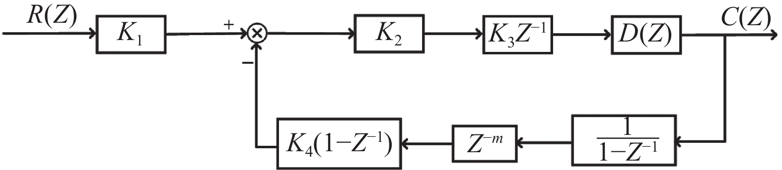
图 2 闭环光纤陀螺线型模型
Figure 2. Linear model of closed-loop fiber optic gyroscope
由图2可知ICFOG闭环传递函数如公式(5)所示:
$$ G(Z) = \dfrac{{C(Z)}}{{R(Z)}} = \dfrac{{{K_1}{G_1}(Z)}}{{1 + {G_1}(Z)H(Z)}} = \dfrac{{{K_1}{K_2}{K_3}D(Z)}}{{1 + {K_2}{K_3}{K_4}{Z^{ - m - 1}}D(Z)}} $$ (5) 式中:前馈通道${G_1}(Z) = {K_2}{K_3}{Z^{ - 1}}D(Z)$,反馈通道$H(Z) = {K_4}(1 - {Z^{ - 1}}){Z^{ - m}}\dfrac{1}{{1 - {Z^{ - 1}}}}$。
根据图2中的线型模型方框图计算可知,误差传递函数如公式(6)所示:
$$ {G_e}(Z) = \dfrac{{{K_1}}}{{1 + {K_2}{K_3}{K_4}{Z^{ - m - 1}}}} $$ (6) 目前数字逻辑控制器$D(Z)$通常使用PID控制器,但是在实际应用中,光纤陀螺系统需要快速地跟踪输入角速率的变化,且稳态误差需要保证为零,因此为了到达此效果,需要对传统的PID进行改进优化。其稳态误差的计算公式如公式(7)所示:
$$ {{{e}}_{ss}}(\infty ) = \mathop {\lim }\limits_{t \to \infty } {{{e}}^*}(t) = \mathop {\lim }\limits_{Z \to 1} (1 - {Z^{ - 1}})E(Z) $$ (7) 当输入恒定的角速率$R(Z) = \dfrac{A}{{1 - {Z^{ - 1}}}}$时,根据公式(7)可知,系统的稳态误差如公式(8)所示。
$$ {e_{ss}} = \mathop {\lim }\limits_{Z \to 1} (Z - 1)E(Z) = \mathop {\lim }\limits_{Z \to 1} (Z - 1){G_e}(Z)R(Z) = 0 $$ (8) 考虑输入角速率为阶跃函数,根据终值定理可得输出如公式(9)所示:
$$ \mathop {C(n){\text{ }}}\limits_{Z \to \infty } = \mathop {\lim }\limits_{Z \to 1} (Z - 1)G(Z)R(Z) = \dfrac{{{K_1}}}{{{K_4}}} $$ (9) 式中:${K_1}/{K_4}$为闭环光纤陀螺的放大倍数,即陀螺的标度因素。
-
PID控制器已经在消除稳态误差、抑制偏差变化和提高响应速度等方面取得了一定的改善。然而,在陀螺工作过程中,仪器的震动或干扰因素会对其对象的特性参数或结果产生影响,从而导致传统PID控制器中固定参数的控制策略效果不佳。为了解决这个问题,文中提出一种新型的PSO-PID控制器。该控制器结合了粒子群优化算法,可以在运行过程中通过在线调整参数${K_p}$,${K_i}$,${K_d}$,从而改善控制效果。通过粒子群优化算法的迭代和搜索过程,PSO-PID控制器能够动态地适应系统的变化,并通过不断优化参数来提高控制性能,使得控制器能够更加灵活地应对不同的工作环境和干扰条件,从而提高控制系统的稳定性和准确性。
此次设计采用自适应控制策略的PID控制器。PSO算法将初始化一组由位置、速度和适应度组成的三维粒子群,其中的三个位置矢量分别对应控制参数${K_p}$,${K_i}$,${K_d}$,并进行搜索和更新。当粒子群经过迭代进化,使其个体极值与全局极值满足适应度函数要求,或者达到最大迭代次数时,即完成对最优解的搜索。基于PSO算法的PID控制系统的原理如图3所示。
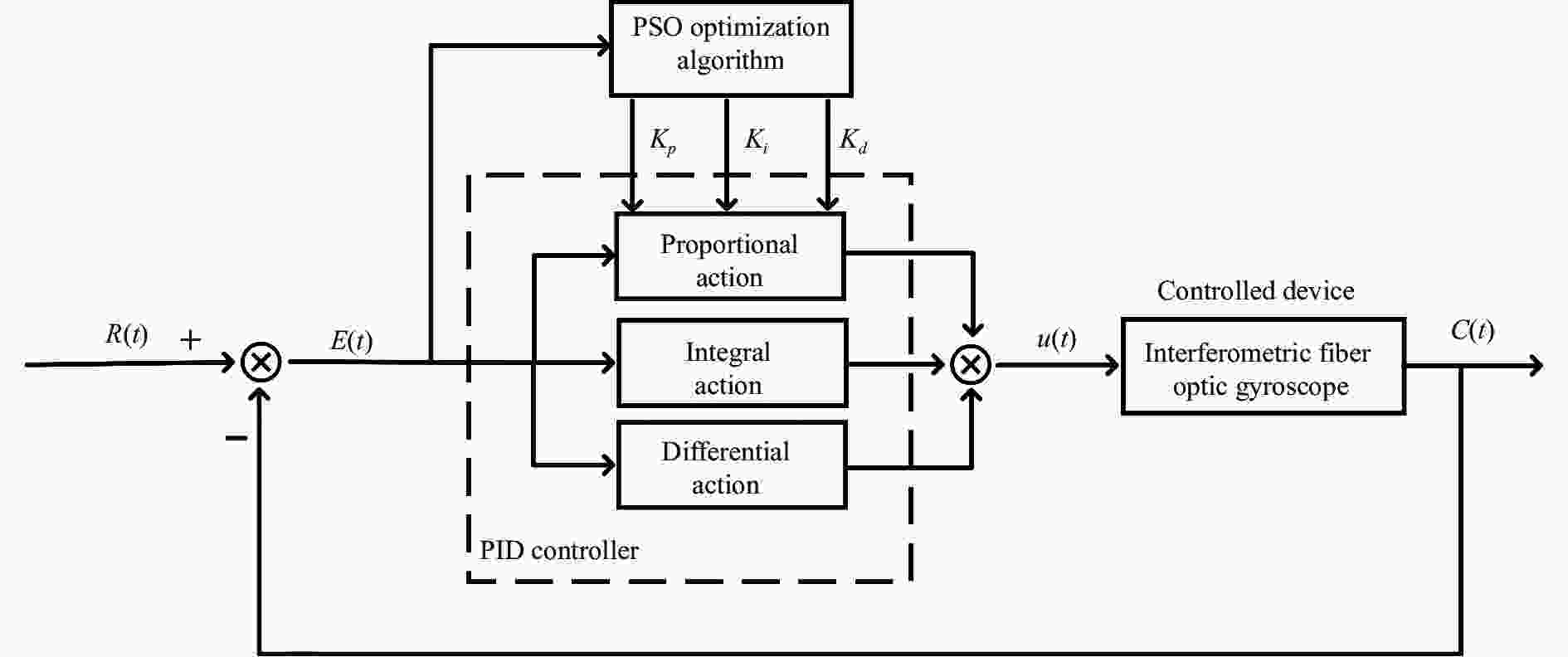
图 3 基于PSO算法的PID控制器原理图
Figure 3. Schematic diagram of PID controller based on PSO algorithm
图3所示的典型的PID控制器如公式(10)所示:
$$ u(t) = {K_p}e(t) + {K_i}\int_0^t {e(\tau ){\mathrm{d}}t + {K_d}\dfrac{{{\rm{d}}e(t)}}{{{\mathrm{d}}t}}} $$ (10) 式中:$e(t) = R(t) - C(t)$,$R(t)$为系统输入,$C(t)$为系统输出;$u(t)$为控制器,$ {K_p} $、${K_i}$、${K_d}$分别为比例、积分和微分系数。
-
选取时间乘以误差绝对值积分(Integral Time Absolute Error, ITAE)作为PID控制器性能评价指标,如公式(11)所示:
$$ ITA{E_{{\rm{min}}}} = \int_0^\infty {t|{{e}}(t)|{\mathrm{d}}t} $$ (11) 式中:$ITA{E_{{\rm{min}}}}$的值越小,代表PID控制器的性能越好。
-
假设在$M$维目标收缩空间中,由$n$个粒子个体组成的种群$X = ({X_1},{X_2}, \cdots ,{X_n})$,第$i$个粒子表示为一个$M$维向量${X_i} = {({x_{i1}},{x_{i2}}, \cdots ,{x_{iM}})^{\mathrm{T}}}$,第$i$个粒子的飞行速度也是一个$M$维向量,表示为${V_i} = $$({v_{i1}},{v_{i2}},$$ \cdots ,{v_{iM}}{)^{\mathrm{T}}}$,个体极值为${P_{{\rm{best}}}} = ({p_{i1}},{p_{i2}}, \cdots ,$${p_{iM}})$,全局极值为${G_{{\rm{best}}}} = ({g_{i1}},{g_{i2}}, \cdots ,{g_{iM}})$,$i = 1,2, \cdots ,N$,根据个体极值和全局极值并结合公式(12)和公式(13)来更新速度和位置。
$$ \begin{split} & {V_{{\rm{im}}}}(t + 1) = \omega {V_{{\rm{im}}}}(t) + {c_1}{r_1}({P_{{\rm{best}}}}(t) -{X_{{\rm{im}}}}(t)) + \\&\qquad\qquad {c_2}{r_2}({C_{{\rm{pest}}}} - {X_{{\rm{im}}}}(t)) \end{split} $$ (12) $$ {X_{{\rm{im}}}}(t + 1) = {X_{{\rm{im}}}}(t) + {V_{{\rm{im}}}}(t + 1) $$ (13) 式中:$\omega $为惯性权重,通常取$[0.5,1.5]$;${c_1}$、${c_2}$为学习因子,一般取值[1, 4],通常设置${c_1} = {c_2} = 2$。对于每个维度,粒子速度受到${V_{{\rm{max}}}}$(${V_{{\rm{max}}}} \gt 0$)的上限约束,若某维速度超过${V_{{\rm{max}}}}$,则该维速度被限制为${V_{{\rm{max}}}}$。
-
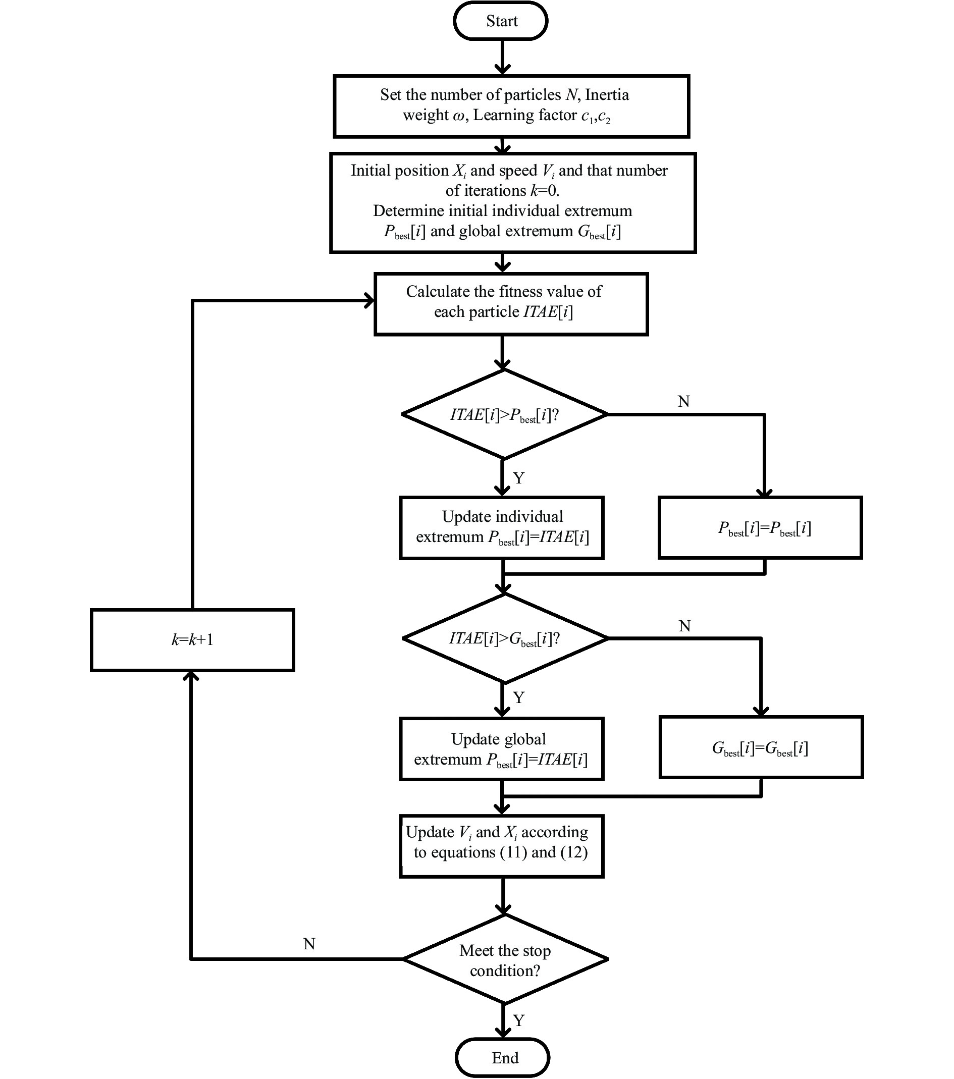
基于标准PSO算法[17]对PID控制器参数进行优化设计,具体流程如图4所示,主要步骤包括:

图 4 基于PSO优化算法的PID整定流程
Figure 4. PID tuning process based on PSO optimization algorithm
步骤1初始化粒子群,确定粒子群的大小$N$和每个粒子的位置${X_i}$和速度${V_i}$。
步骤2根据公式(11)计算每个粒子的自适应度值$ITAE[i]$。
步骤3个体极值${P_{{\rm{best}}}}[i]$和自适应度值$ITAE[i]$作比较,如果$ITAE[i]$$\gt {P_{{\rm{best}}}}[i]$,则个体极值${P_{{\rm{best}}}}[i]$被替换成$ITAE[i]$,否则个体极值$ITAE[i]$不发生改变。
步骤4适应度值$ITAE[i]$和全局极值${G_{{\rm{best}}}}[i]$作比较,如果$ITAE[i]$$\gt {G_{{\rm{best}}}}[i]$,则全局极值${G_{{\rm{best}}}}[i]$被替换成$ITAE[i]$,否则全局极值${G_{{\rm{best}}}}[i]$不发生改变。
步骤5根据公式(12)和公式(13)更新粒子的速度${V_i}$和粒子的位置${X_i}$。
步骤6判断是否满足停止条件,如达到最大迭代次数或适应度值足够小等。
步骤7如果满足停止条件,则退出,否则回到步骤2继续执行,直到满足停止条件。
-
为实现闭环光纤陀螺系统的精确控制,BP-PID控制器的控制算法如下[18]:
步骤1 初始化参数,即选定输入层节点数$M$和隐含层节点数$Q$,并给出各层加权系数的初值,选定学习速率$\eta $和惯性系数$\alpha $;
步骤2 采样得到$R(k)$和$C(k)$,计算误差$e(k) = R(k) - C(k)$;
步骤3 对输入$R(i)$,输出$C(i)$,控制器$u(i - 1)$$(i = k,k - 1, \cdots ,k - p)$进行归一化处理,作为BP神经网络的输入;
步骤4 计算BP神经网络各层的输入和输出,其中输出层的输出即为PID控制器的三个可调参数${K_p}$,${K_i}$,${K_d}$;
步骤5 计算PID控制器的控制输出,并将其用于控制和计算;
步骤6 计算修正输出层的加权系数;
步骤7 计算修正隐含层的加权系数;
步骤8 令$k = k + 1$,返回到步骤2。
基于BP神经网络的PID参数整定算法流程图如图5所示。

图 5 基于BP神经网络PID参数整定流程图
Figure 5. PID parameter tuning flow chart based on BP neural network
-
通过模糊PID实现闭环光纤陀螺的控制,图6为该系统的模糊自整定PID控制结构图。

图 6 基于模糊PID参数整定流程图
Figure 6. Flow chart of parameter tuning based on fuzzy PID
根据图6所示,闭环光纤陀螺的控制系统以陀螺输出$C(t)$与理想值$R(t)$之间的偏差${{e}}$和$ec$作为输入信号,通过模糊化得到两个变量$E$和$EC$作为输入语言变量。随后根据模糊推理机和规则库进行计算,最后经过去模糊化得到准确得控制系数$\Delta {K_p}$、$\Delta {K_{{i}}}$、$\Delta {K_d}$,从而实现对PID控制器得参数进行调节。
-
以某型号的光纤陀螺的结构参数为例,进行动态仿真研究。此光纤陀螺的光纤环的长度$L = 600$ m,光纤环的直径$D = 0.1$ cm,光纤光源产生的激光束在真空中的波长$\lambda = 1\;550$ nm,根据公式(1)可知,${K_1} = $$\dfrac{{2\pi \times 600 \times 0.1}}{{1\;550 \times {{10}^{ - 9}} \times 3 \times {{10}^8}}}$$ = \dfrac{{120\pi }}{{155}}$,${K_2} = 1$,${K_3} = \dfrac{{212}}{{2.6}}$,$ {K_4} = \dfrac{{2\pi }}{{{2^{16}}}} $,前向滞后为1,后向滞后为2,采样时间为光纤环的渡越时间:$\tau = \dfrac{L}{c} = 2 \;{\text{μs}}$。
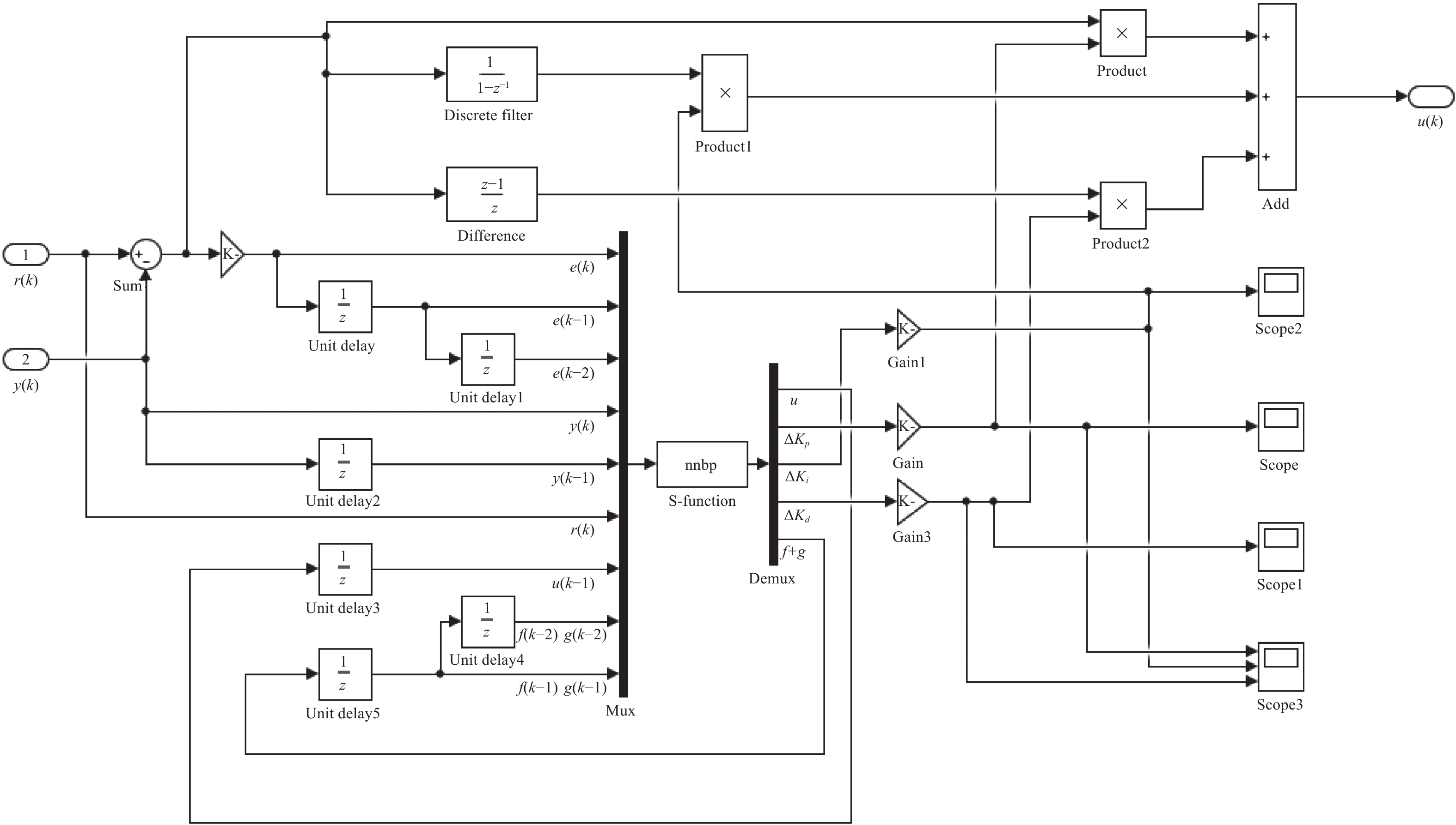
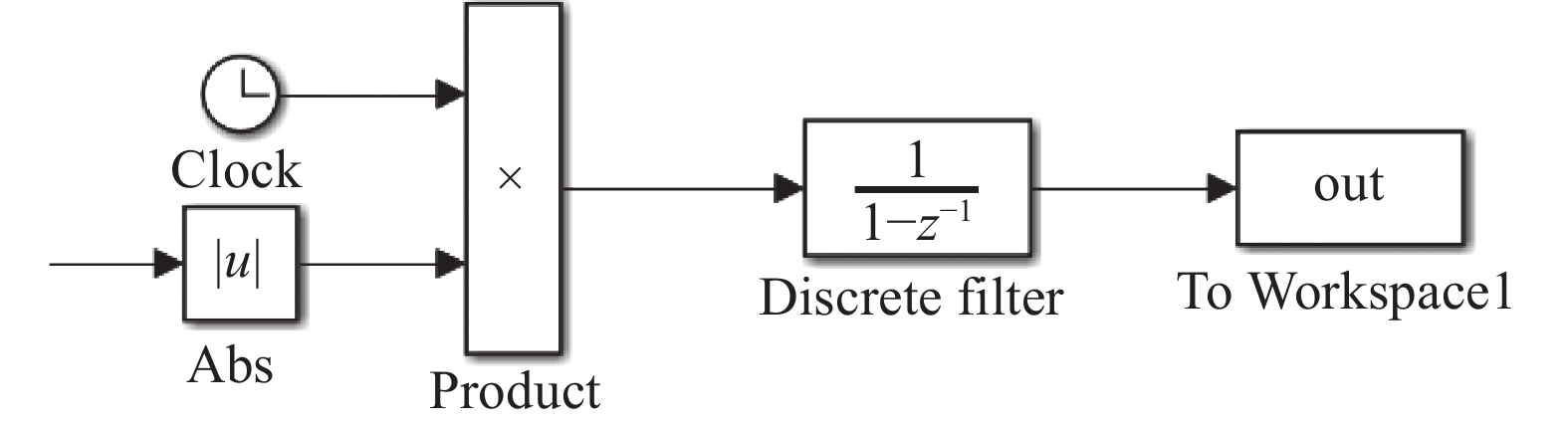
仿真对比目前使用的参数固定PID控制器、BP神经网络整定PID参数(BP-PID)、模糊控制整定PID参数(F-PID)以及文中所提的PSO优化PID参数(PSO-PID),PID控制器如图7所示,BP-PID控制器如图8所示,F-PID控制器如图9所示,PSO-PID控制器如图10所示,PSO优化PID控制器适应度函数选择如图11所示。

图 7 PID控制器
Figure 7. PID controller
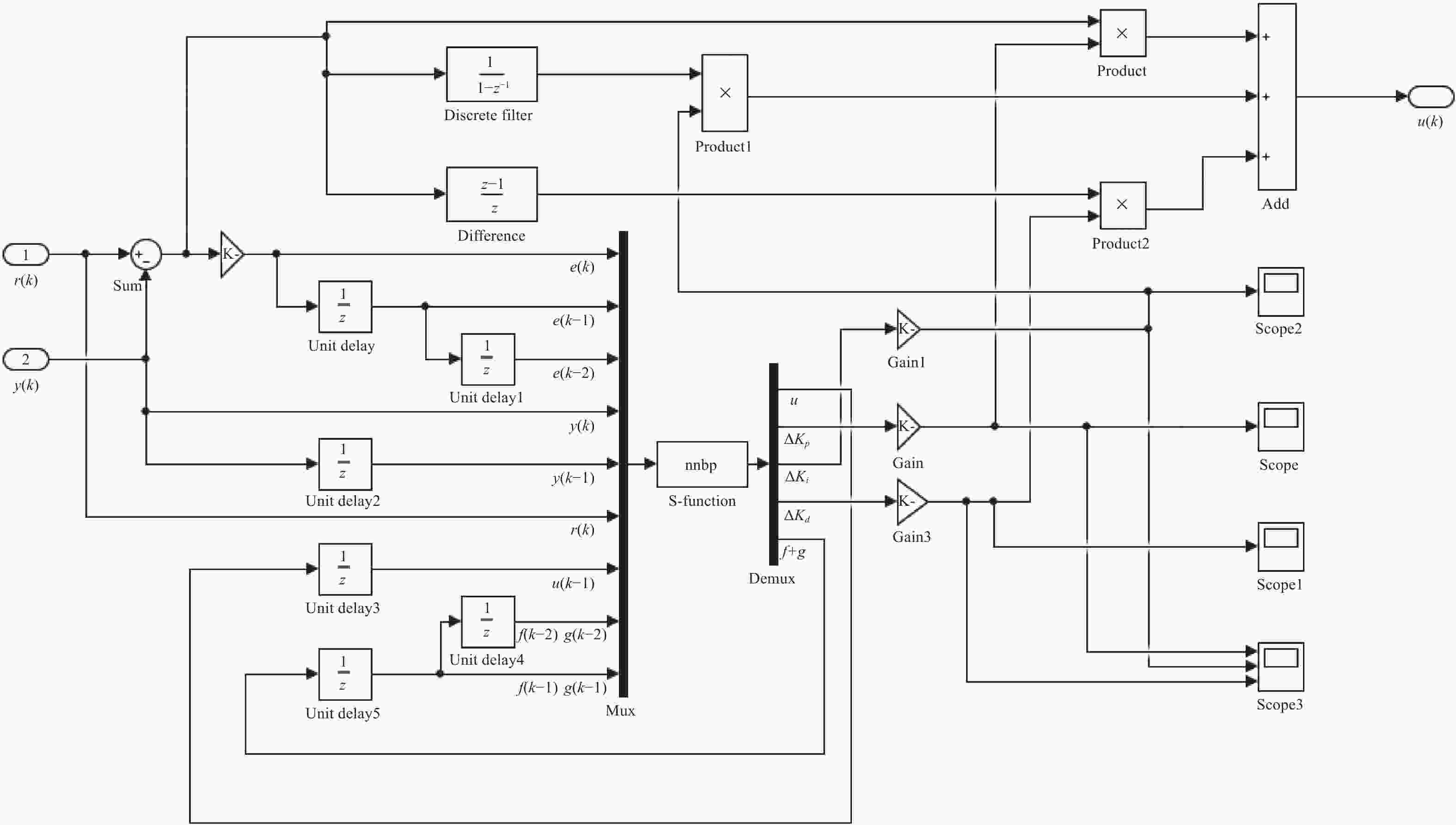
图 8 BP-PID控制器
Figure 8. BP-PID controller
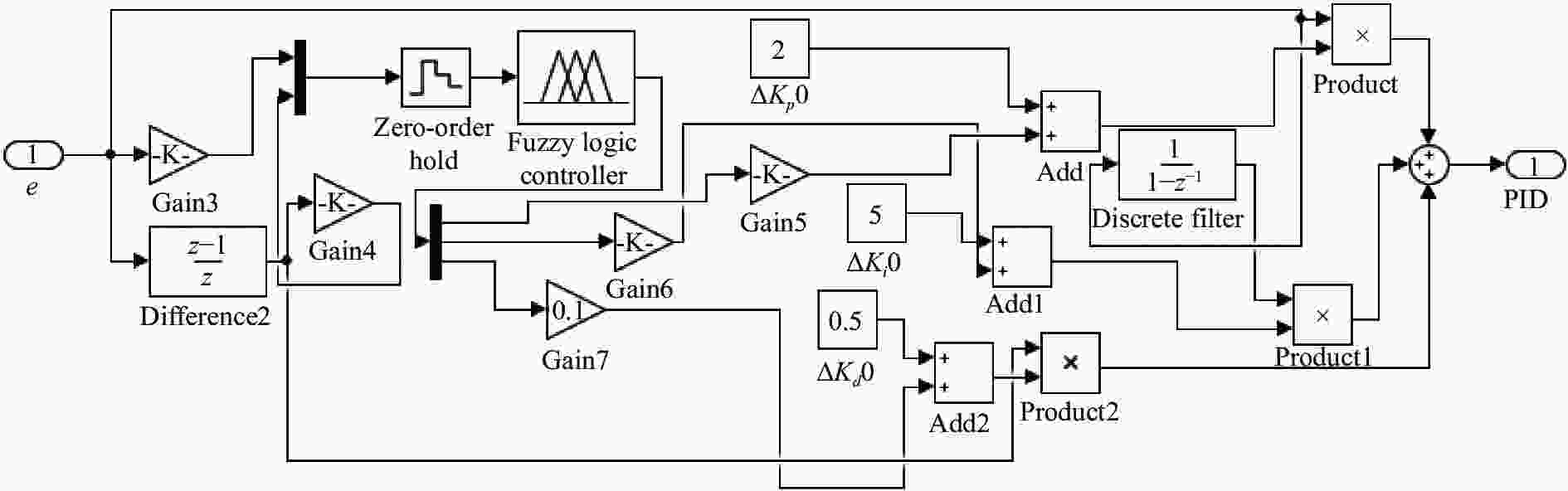
图 9 F-PID控制器
Figure 9. F-PID controller
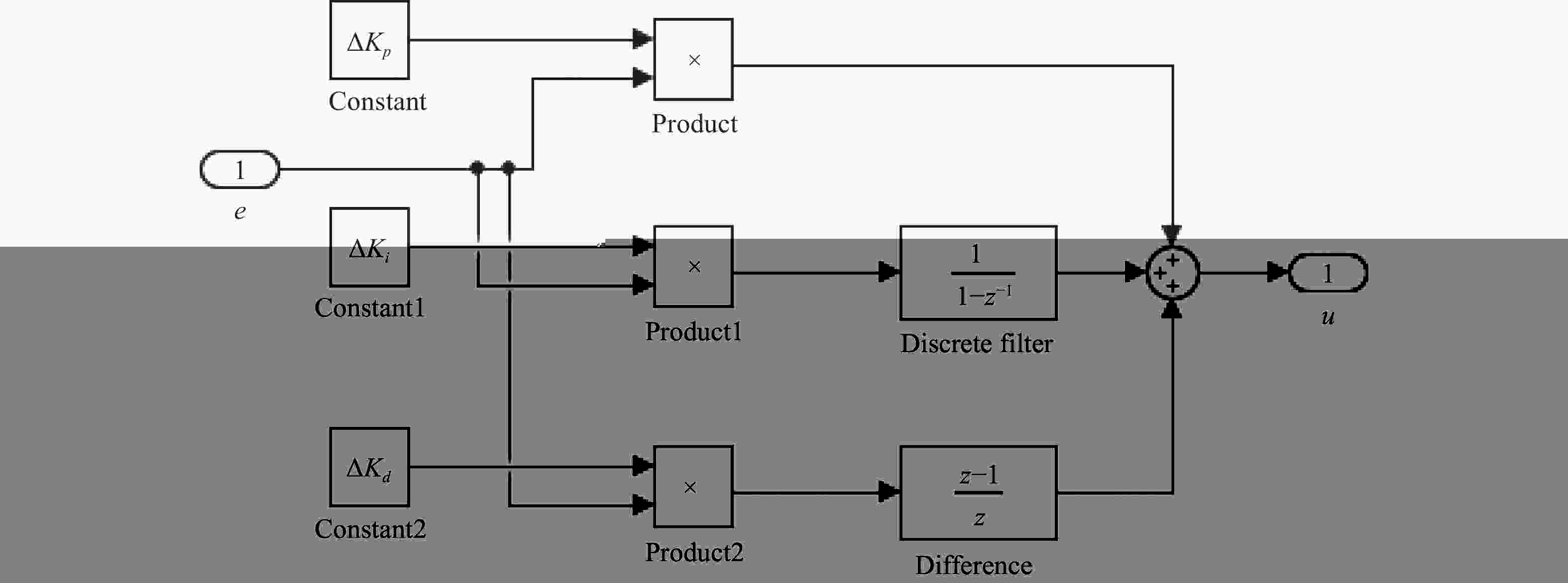
图 10 PSO-PID控制器
Figure 10. PSO-PID controller

图 11 PSO优化算法适应度函数
Figure 11. Fitness function of PSO optimization algorithm
综上所述,PSO-PID控制方法,粒子群初始参数的选取如下:因为是对控制参数${K_p}$、${K_i}$、${K_d}$进行优化,因此维度为3,种群大小不宜过大,因为过大的种群会增加算法的计算复杂度和内存消耗,同时也可能导致算法陷入过度探索的情况,影响算法的收敛性和搜索效果。在保证收敛和跟踪效果的情况下,种群大小选取为15。微粒数量$N$=20,${K_p}$的区间为[0.3,100],${K_i}$的区间为[0.01,15],${K_d}$的区间为[0.1,0.5]。学习因子${c_1} = 0.8$,${c_2}$=0.5。惯性权重$\omega = 0.9$。粒子速度的上限约束${V_{{\rm{max}}}} = 2$,粒子速度的下限约束${V_{\min }} = - 2$。使用PID控制方法,其控制参数${K_p} = 2$,${K_i} = 2$,${K_d} = 0.5$。使用F-PID控制方法,${K_p}$,${K_i}$,${K_d}$模糊子集均为{NB,NM,NS,ZO,PS,PM,PB},量化等级为{−6,−5,−4,−3,−2,−1,0,1,2,3,4,5,6}。使用 BP-PID 控制方法,设置参数为:输入层节点个数为4,隐含层节点个数为5,输出层节点个数为3;学习因子为0.25,惯量因子为0.05,采样时间为0.001 s。
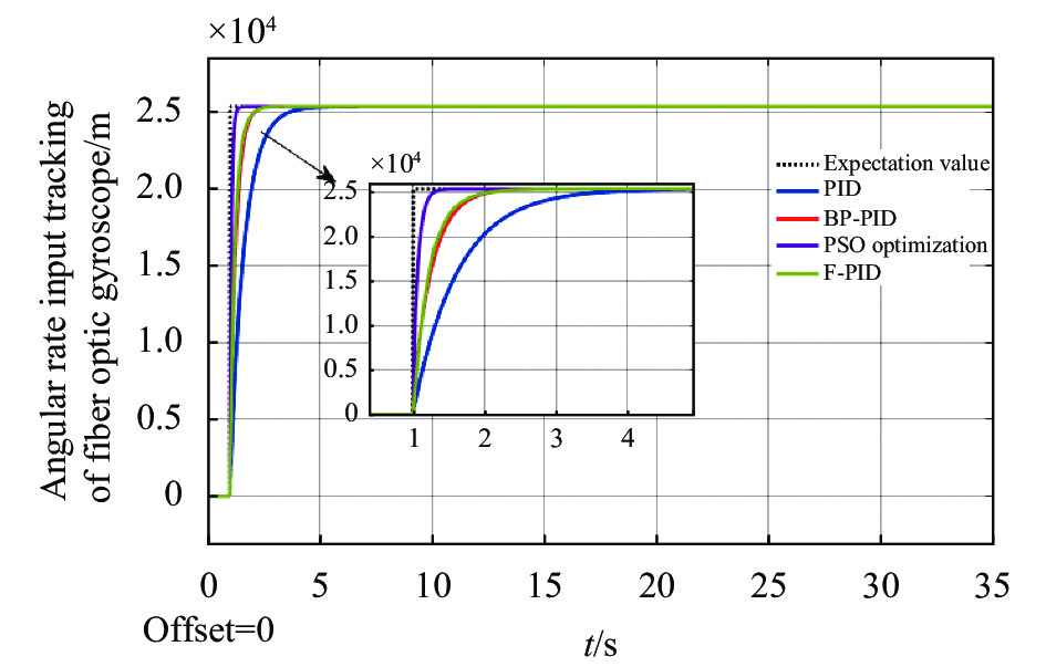
使用不同控制方案光纤陀螺角速率输入跟踪对比如图12所示,图13为不同控制方案光纤陀螺角速率输入跟踪误差对比图,表1为不同控制方案下系统的动态性能,根据图12、图13和表1的数据,可得PSO-PID控制方法的跟踪时间为1.2 s,其跟踪陀螺仪角速率的速度更快。与BP-PID控制方法相比,其跟踪速度提高了1.91倍;相对于PID控制方法,其跟踪速度提高了3.5倍;而相对于F-PID控制方法,其跟踪速度提高了1.75倍。经PSO-PID控制方法后,跟踪误差为$4.740\;8 \times {10^4}$m,相较于其他控制方法,PSO-PID的跟踪误差更小。与F-PID控制方法相比,其控制精度提高了45.27%;与BP-PID控制方法相比,其控制精度提高了46.03%;与PID控制方法相比,其控制精度提高了66.30%。

图 12 不同控制方案光纤陀螺角速率输入跟踪对比图
Figure 12. Comparison chart of angular rate input tracking of fiber optic gyro with different control schemes
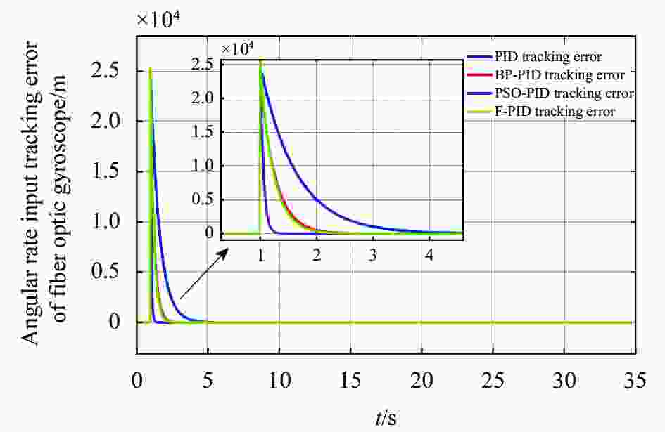
图 13 光纤陀螺角速率输入跟踪误差对比图
Figure 13. Comparison chart of angular rate input tracking error of fiber optic gyroscope
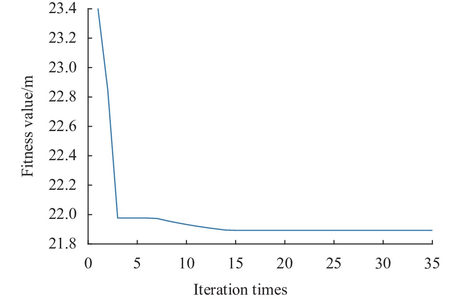
图14为文中粒子群算法中适应度值随着迭代次数的变化情况。从图中可以看出,变化趋势较快,当迭代次数为15时,适应度值达到最优解,最优解为21.892 5。图15为PID控制器参数${K_p}$,${K_i}$,${K_d}$值随迭代次数变化图,根据图示可见,随着迭代次数的增加,控制器参数逐渐稳定在一个恒定的有界值内,逐渐趋于稳定。根据图中的变化趋势可知,可以进行在线调节,寻找最优值。由图可知是有界得,可以在线调节寻优。
表 1 不同控制方法系统动态性能比较
Table 1. Comparison of dynamic performance of different control methods system
Control method Tracking time/s Tracking error norm/m PID control method 4.2 $1.406\;7 \times {10^5}$ BP-PID control method 2.3 $8.784\;4 \times {10^4}$ F-PID control method 2.1 $8.662\;3 \times {10^4}$ PSO-PID control method 1.2 $4.740\;8 \times {10^4}$ 
图 14 适应度值随迭代次数变化图
Figure 14. Variation diagram of fitness value with iteration times

图 15 参数${K_p}$,${K_i}$,${K_d}$随迭代次数变化图
Figure 15. Variation diagram of parameters ${K_p}$,${K_i}$ and ${K_d}$ with iteration times
-
文中基于对干涉式闭环光纤陀螺仪的研究,通过分析其动态性能,对传统数字控制器进行了改进,并提出了采用PSO-PID控制器。通过与多种控制方法进行仿真对比,仿真结果表明PSO-PID控制器能够缩短调节时间,减小超调,并且易于实现,具有重要的工程意义和实用价值。此优化方案要应用到工程实践中去还需要考虑更多的外界影响因素和更为详细的控制参数分析,这将是后期研究的重点。
Optimization method of PSO-PID control for interferometric closed-loop fiber optic gyroscope
-
摘要: 控制系统的设计会对响应速度快且应用范围较广的数字干涉式闭环光纤陀螺(ICFOG)动态性能产生影响。通过分析ICFOG的工作原理,推导出闭环离散控制系统,并利用粒子群优化算法(Particle Swarm Optimization,PSO)对传统的PID控制器参数进行优化。基于这个优化过程,设计一种新型的PSO-PID复合控制器,以取代传统的PID控制器。通过与其他BP神经网络、模糊控制等方法进行对比凸显该控制方法的优越。通过数字仿真分析显示,跟踪速度相较于BP-PID控制方法提高了1.91倍,相对于PID控制方法提高了3.5倍,相对于F-PID控制方法提高了1.75倍。同时,控制精度相对于BP-PID控制方法提高了46.03%,相对于PID控制方法提高了66.30%,相对于F-PID控制方法提高了45.27%。结果显示,采用PSO-PID控制器能够快速达到控制目标且具有较小的超调量。
-
关键词:
- 干涉式光纤陀螺 /
- 小超调量 /
- 粒子群优化PID方法 /
- BP神经网络 /
- 模糊控制器
Abstract:Objective PSO-PID control optimization algorithm based on the interferometric closed-loop fiber optic gyroscope has been widely used in military and civil fields, such as aerospace, defense equipment, navigation survey, vehicle inertial navigation system and other industrial systems. These applications are developing in the direction of lightness, low power consumption, long life, high reliability, no self-locking and mass production. PSO-PID controller can improve the dynamic response of fiber optic gyroscope and effectively track the angular rate input of fiber optic gyroscope. Fiber optic gyroscope is based on Sagnac effect in closed optical path, so its bandwidth is much larger than that of traditional gyroscope. In digital closed-loop fiber optic gyroscope, the response speed of optical path is very fast, and the system bandwidth is mainly determined by the detection circuit. Choosing a suitable digital controller is helpful to improve the dynamic performance of fiber optic gyroscope. Methods The system block diagram of fiber optic gyroscope (Fig.1) is established, and the ICFOG closed-loop system is equivalent to a mathematical model (Fig.2) by analyzing the working principle of fiber optic gyroscope, and finally the closed-loop discrete control system is deduced. On this basis, a new PSO-PID compound controller is designed (Fig.3), and the optimization algorithm steps of PID controller of standard PSO are analyzed (Fig.4). The controller can adjust parameters ${K_p}$,${K_i}$ and ${K_d}$ online during operation (Fig.15). At the same time, by comparing with the PID parameter tuning method of BP neural network (Fig.5), fuzzy PID parameter tuning method (Fig.6) and PID control method, the advantages of PSO-PID control are illustrated by comparing the angular rate input tracking speed of fiber optic gyro (Fig.12) and the angular rate input tracking error of fiber optic gyro (Fig.13). Results and Discussions Using PSO-PID control method, it is found that the fitness value changes rapidly. When the number of iterations is 15, the fitness value can reach the optimal solution, and the optimal solution is 21.892 5. At the same time, the tracking time of FOG angular rate input is 1.2 s. Compared with BP-PID, PID, and F-PID control methods, the tracking speed is increased by 1.91, 3.5 and 1.75 times respectively. After the PSO-PID control method, the tracking error is $4.7 \times {10^4}$ m, which is smaller than other control methods. Compared with F-PID, BP-PID and PID control methods, its control accuracy is improved by 45.27%, 46.03% and 66.30% respectively. According to the comparison of dynamic performance of different control methods (Tab.1), it is known that PSO-PID controller can achieve the control goal quickly and has a small tracking error. Conclusions Based on the mathematical model of fiber optic gyro, this paper puts forward an optimization scheme of fiber optic gyro digital controller. The traditional digital controller is improved, and the PSO-PID controller is proposed and simulated. Compared with many control methods, the simulation results show that PSO-PID controller can shorten the adjustment time and reduce overshoot, thus effectively improving the dynamic performance of fiber optic gyroscope on the premise of ensuring stability, and has important engineering significance and practical value. To apply this optimization scheme to engineering practice, more external factors and more detailed control parameter analysis need to be considered, which will be the focus of later research. -
Key words:
- ICFOG /
- small overshoot /
- PSO-PID /
- BP neural network /
- fuzzy controller
-
图 3 基于PSO算法的PID控制器原理图
Figure 3. Schematic diagram of PID controller based on PSO algorithm
图 4 基于PSO优化算法的PID整定流程
Figure 4. PID tuning process based on PSO optimization algorithm
图 5 基于BP神经网络PID参数整定流程图
Figure 5. PID parameter tuning flow chart based on BP neural network
图 12 不同控制方案光纤陀螺角速率输入跟踪对比图
Figure 12. Comparison chart of angular rate input tracking of fiber optic gyro with different control schemes
图 13 光纤陀螺角速率输入跟踪误差对比图
Figure 13. Comparison chart of angular rate input tracking error of fiber optic gyroscope
图 15 参数${K_p}$,${K_i}$,${K_d}$随迭代次数变化图
Figure 15. Variation diagram of parameters ${K_p}$,${K_i}$ and ${K_d}$ with iteration times
表 1 不同控制方法系统动态性能比较
Table 1. Comparison of dynamic performance of different control methods system
Control method Tracking time/s Tracking error norm/m PID control method 4.2 $1.406\;7 \times {10^5}$ BP-PID control method 2.3 $8.784\;4 \times {10^4}$ F-PID control method 2.1 $8.662\;3 \times {10^4}$ PSO-PID control method 1.2 $4.740\;8 \times {10^4}$  下载: 导出CSV
-
[1] Meng Zhixin, Yan Peiqiang, Wang Shengzhe, et al. Research status and analysis of atom interferometer gyroscope [J]. Navigation and Control, 2022, 21(Z2): 19-32. (in Chinese) [2] Lei Ming, Li Haowei, Yu Xiaozhi, et al. Development status and trend of integrated fiber optic gyroscope [J]. Semiconductor Optoelectronics, 2022, 43(4): 666-671. (in Chinese) [3] Ma Liming, Zhao Tao, Wang Kuimin. Optimization design and simulation of digital controller for fiber optic gyroscope [J]. Telecom World, 2018(7): 257-260. (in Chinese) [4] Wang Yan, Zhang Chunxi, Liu Zhenping. Design and simulation of a digital controller for closed-loop fiber optic gyroscopes [J]. Opto-Electronic Engineering, 2004, 31(B12): 4. (in Chinese) [5] Sun Liang, Yu Zhenhong, Chen Hao, et al. Application of F-PID composite controller in closed-loop fiber optic gyroscope [J]. Modern Electronic Technology, 2013, 36(13): 160-163. (in Chinese) [6] Ju Chao, Ye Min, Feng Kaiyang, et al. High speed sweeper swing arm control system based on BP network PID [J]. Machine Tool & Hydraulics , 2023, 51(14): 106-112. (in Chinese) [7] Bu Tongjie, Wang Yagang. PID liquid level control for beer filling based on improved grey wolf algorithm [J]. Packaging Engineering , 2023, 44(21): 245-252. (in Chinese) [8] Yang Sen. Hybrid PSO-AMLS-based method for data fitting in thecalibration of the infrared radiometer [J]. Infrared and Laser Engineering, 2021, 50(8): 20200471. (in Chinese) doi: 10.3788/IRLA20200471 [9] He Yanping, Liu Xinxue, Cai Yanping, et al. New aircraft terrain matching algorithm based on particle swarm optimization [J]. Infrared and Laser Engineering, 2016, 45(S1): 115-120. (in Chinese) [10] Ma Dazhong, Zhai Xiaojun, Sun Qiuye. Maximum power point tracking and controlling based on compound PSO [J]. Infrared and Laser Engineering, 2015, 44(12): 3801-3806. (in Chinese) [11] Tang Yulan, Xu Mingliang, Mei Juan, et al. Research and application of particle swarm optimization in parameter tuning on PID controller [J]. Computer Engineering and Applications, 2012, 48(34): 221-224. (in Chinese) [12] Dai Chenxi, Zhou Fangwei, Wei Xiaojuan. Chaos control for a class of vibro-impact system based on PSO optimization [J]. Journal of Technology, 2022, 22(3): 270-275. (in Chinese) [13] Tuo Jingyi, Xu Bingfeng, Xu Yue, et al. Coagulation dosing control in waterworks based on RBF neural network optimized by PSO algorithm [J]. Industrial Safety and Environmental Protection, 2022, 48(9): 83-86. (in Chinese) [14] Lin Xinyou, Huang Qiang, Zhang Guangji. Torque distribution strategy optimization of a novel dual-motor multi-mode drive system using PSO algorithm [J]. Automotive Engineering, 2022, 44(8): 1218-1225. (in Chinese) [15] Tang Jun, Hong Zhimin, Luo Ruizhi, et al. Depth control of LADRC underwater robot based on PSO optimization [J]. Ship Science and Technology, 2022, 44(13): 111-116. (in Chinese) [16] Arditty H J, Lefevre H C. Theoretical basis of Sagnac effect in fiber gyroscopes[C]//Fiber-Optic Rotation Sensors and Related Technologies: Proceedings of the First International Conference MIT, Cambridge, Mass, USA, November 9–11, 1981, 1982: 44-51. [17] Shi Y H, Eberhart R C. A modified particle swarm optimizer [J]. IEEE International Conference on Evolutionary Computation, Anchorage, 1998(2): 69-73. [18] Zhang Yizhuo, Liu Buyu, Ma Lin. Application of BP-PID control method in the control system of variable rate fertilizer [J]. Modern Electronic Technology, 2012, 35(5): 192-194. (in Chinese) -

 点击查看大图

计量
- 文章访问数: 29
- HTML全文浏览量: 6
- PDF下载量: 15
- 被引次数: 0

