


-
临近空间热环境与地面热环境有很大的区别,其温度范围较大,临近空间热环境特性随着高度的变化也有所差别。光通信系统和激光雷达系统的接收端采用离轴抛物面反射镜来收集光信号,离轴系统具有无中心遮拦的优势,选用多模光纤作为传输介质。温度变化会导致反射镜的形状发生变化,当温度降低时,反射镜收缩,曲率半径发生变化,从而影响焦平面位置和光纤的耦合效率[1−2]。
潘翔等[3]设计了一套抛物面天线热补偿系统,热补偿主要通过计算并下发指向调整量至天线控制单元(Antenna Control Unit, ACU),从而修正由于热变形导致的指向偏差,达到热补偿目的,但需要在天线上安装大量传感器才能反演出天线温度场。Bernd Kaifler等[4]设计了一种球载激光雷达,能够在100 m的垂直分辨率和30 s的时间分辨率下探测体积后向散射系数低至0.6×10⁻¹⁰ m−1·sr−1的极地中间层云层,但在实际应用时,光学系统的最后一个镜头和雪崩光电二极管(Avalanche Photo Diode, APD)探测器之间的离焦导致检测到的激光雷达信号降低了38%。管雯璐等[5]设计了一种基于环境温度反馈的望远镜自动调焦装置,通过电动步进电机调整离焦量来减少温度的影响。该调焦装置能够抑制背景噪声,提高信号采集的精确度与参数测量的准确度,但分析对象为卡塞格林系统,无法用于其他形式的反射镜。汤伟等[6]设计了18点浮动支撑主镜结构,有效地减小了镜面在−20 ℃下的热变形,镜面峰谷(Peak Valley, PV)值小于λ/10,但背部18点支撑存在一定的过定位问题,工程上加工复杂。
文中设计了自动热补偿激光雷达主镜组件,反射镜采用离轴抛物面,可以减小系统遮光比,系统焦距为1300 mm。分析了不同温度下离轴抛物面反射镜最佳焦点位置,其最佳焦点位置与温度之间成近似线性关系,通过热适应自动调焦机构,无需额外安装电动驱动器和温度传感器来获得镜面温度数据即可达到调整焦点的效果,使该系统能够在临近空间运行,耦合效率满足系统需求。
-
临近空间是指距离地面20~100 km的空域,包括平流层(18~55 km空域)、大气中间层(55~85 km空域)和小部分增温层区域(85~800 km空域)。将大气温度随高度变化的分布作为主要依据,可将大气分为四个层:对流层、平流层、中间层和热层。
平流层飞艇一般航行高度位于20 km,不同大气模型在此处的温度预测值不同[7],标准大气模型的温度预测值为216.65 K;极热大气模型的温度预测值为234.87 K;极冷大气模型的温度预测值为192.28 K。上述大气模型的温度随高度的变化趋势如图1所示。

图 1 不同大气模型温度分布趋势
Figure 1. Temperature distribution trends of different atmospheric models
-
反射镜的焦距主要受其曲率半径的影响,两者成正比关系。由于离轴抛物面反射镜的特性,反射镜背板与镜面曲率中心的距离减少,背板的厚度也随之减小。在镜面工作温度为−60℃时,根据热膨胀公式可知其厚端的变形量大于薄端的变形量,反射镜在不同位置发生的形变随着厚度的增加而增大,导致曲率半径增大,反射面上各点的变形量也不同,进而使得曲率半径增大,焦点远离镜面。
$$ \Delta L = L \times \alpha \times \Delta T $$ (1) 式中:ΔL为物体热变形后的长度;L为初始温度下的长度;α为线膨胀系数;ΔT为温度的改变量。
光学元件微小变形会导致反射镜产生形状复杂的波面误差,用通常的函数难以表示,但镜面波前的变化总是趋于光滑和连续的。因此,可以使用一个完备的基函数的线性组合,或者一个线性无关的基函数系的组合来表示镜面的形状变化[8]。Fringe Zernike构造出的Zernike多项式[9−10]已应用在许多科研领域中。一般使用Zernike多项式来描述干涉图的波前像差,其线性组合能够表示任意k阶波面ω(ρ,θ),如公式(2)所示:
$$ \omega (\rho ,\theta ) = \sum\limits_{i = 1}^N {{q_i}{Z_i}(\rho ,\theta )} $$ (2) 式中:Zi为Zernike多项式的第i项;qi为第i项的系数;N为最大项数。极坐标形式的Zernike多项式具体表达式为[11]:
$$ Z_n^l(\rho ,\theta ) = \left\{ \begin{gathered} R_n^l(\rho )\cos (l\theta ),(l \leqslant 0) \\ R_n^l(\rho )\sin (l\theta ),(l > 0) \\ \end{gathered} \right. $$ (3) 式中:n取自然数,为多项式的阶数;l为与n有关的序号,其值恒与n同奇偶,且$ \left|l\right|\leqslant n $。现假设正整数m定义为$ (n-l)/2 $,则:
$$ R_n^l(\rho ) = \sum\limits_{s = 0}^m {{{( - 1)}^s}\frac{{(n - s)!}}{{s!(m - s)!(n - m - s)!}}{\rho ^{n - 2s}}} $$ (4) 确定基函数后,干涉条纹的级数分布函数如公式(5)所示[9]:
$$ F(\rho ,\theta )={\displaystyle \sum _{{i}=0}^{\infty }{q}_{i}{Z}_{n}^{n-2m}(\rho ,\theta )={q}^{{\rm{T}}}\cdot Z} $$ (5) 式中:qi为Zernike第i项系数;qT为Zernike系数即qi组成的列向量转置;Z为由Zernike多项式项组成的列向量。
在使用Zernike多项式拟合变形反射面时,需要反射面面形的离散数据。通过实验测量或结构分析方法可以获得反射镜的离散数据,例如通过有限元软件进行结构分析,导出的变形输出文件即可用作反射面的离散数据[12]。通过得到的离散变形数据和反射面镜面参数即可进行Zernike多项式拟合。通过Zernike多项式拟合可以获得各项多项式系数,从而得到以Zernike多项式表示的面形误差,并且能够快速拟合出连续光滑的变形形面。反射镜镜面拟合即用Zernike多项式作为连续基函数,用于拟合离散的波相差W(xi, yi),连续函数W(x, y)用于表征被测面形的波相差函数。常用的Zernike多项式为Fringe Zernike多项式和标准Zernike多项式[13−14],选择使用前28项的Fringe Zernike多项式拟合非球面反射镜。
-
在光纤模式相关理论的分析中,光纤主要分为渐变型光纤和阶跃型光纤,分类的原则为光纤的折射率分布方式。纤芯区域的折射率会变化的为渐变型光纤,光纤包层材料的折射率大于纤芯材料折射率,且两者折射率为定值的光纤为阶跃型光纤。
光纤的归一化频率(Normalized Frequency)是决定光纤可以传输多少个模式的光场的参数,归一化频率越大,光纤可以传输的模式数就越多[15]。通过公式(6)可求得归一化频率为:
$$ \begin{gathered} {{V = }}\frac{{2\pi }}{\lambda }\omega \sqrt {n_{ce}^2 - n_{ca}^2} \approx \\ \frac{{2\pi }}{\lambda }\omega {n_{ce}}\sqrt {\frac{{2(n_{ce}^2 - n_{ca}^2)}}{{2n_{ce}^2}}} \approx \frac{{2\pi }}{\lambda }\omega {n_{ce}}\sqrt {2\Delta } \\ \end{gathered} $$ (6) 式中:ω为光纤的纤芯半径;λ为波长;nce为纤芯材料的折射率;nca为包层材料的折射率。
使用多模光纤作为空间激光耦合器件时,其具有更大的纤芯半径,相较于单模光纤和少模光纤,多模光纤具有更高的空间激光-光纤耦合效率,因此文中的激光雷达采用阶跃型多模光纤作为激光接收端。多模光纤纤芯直径为62.5 μm,纤芯材料折射率nce为1.48,包层材料折射率nca为1.46。当空间光波长λ为1.064 μm时,通过公式(6)即可求出归一化频率为44.748。多模光纤对空间激光的耦合效率为其所有线偏振模式的耦合效率之和,文中以基模模式的耦合效率为基准,其耦合效率可以表示为:
$$ {\eta }_{m.1}=\frac{{\left|{\displaystyle \iint {U}_{of}^{\ast }(r)\cdot{U}_{mf.1}(r)\text{d}s}\right|}^{2}}{{\displaystyle \iint \left|{U}_{of}{(r)}^{2}\right|\text{d}s\cdot{\displaystyle \iint \left|{U}_{mf.1}{(r)}^{2}\right|\text{d}s}}} $$ (7) 式中:Uof(r)为空间激光的入射光场经过反射镜后焦平面处的场分布,简化后只保留振幅项;Umf.1(r)为基模对应的场分布。
-
设计分析的对象为离轴抛物面的反射镜系统。入射光波长λ为1.064 μm,主镜面形为正六边形,口径为650 mm的内切圆,曲率半径为2600 mm,焦距为1300 mm;平面支撑背板、后开式结构;支撑方式为背部六点式。要求在标准地球重力下镜面PV值<λ/10,耦合效率在−60 ℃时高于60%。
-
针对几种常见的反射镜材料——碳化硅(SiC)、铝基碳化硅(Al/SiC)、K9、微晶玻璃(Zerodur)、熔石英(Fused silica)和背板金属材料——钛合金TC4、ZTC4、超因瓦合金4J32进行组合配对,对每种反射镜材料和背板材料在临近空间工作时的反射镜热变形和光学性能进行比较,分析其在−60 ℃下、原焦点处的RMS半径的变化量。通过热仿真分析得出了不同材料组合后的结果,不同组合下的RMS值如图2所示,其中SiC+4J32组合的RMS值为21.75 μm,是所有组合中的最小值,其在−60 ℃下的影响最小。

图 2 不同材料组合在−60 ℃下的光学性能对比
Figure 2. Comparison of optical properties of different material combinations at −60 ℃
综合考虑反射镜的机械性能、物理性能、加工工艺以及成本等因素,选定主镜材料为SiC,其具有热畸变小、比刚度大的优点且稳定性好。背板选择4J32,该材料的线膨胀系数与SiC基本一致,可减小热变形不一致带来的影响。桁架及遮光板采用碳纤维复合材料(Carbon Fiber Reinforced Polymer/Plastic, CFRP),其具有高强度、低密度的优点,应用于桁架及遮光板时可以减小自身重力带来的影响,材料的性能参数如表1所示。
表 1 反射镜常用材料属性
Table 1. Properties of commonly used materials for mirrors
Material Density
ρ/kg·m–3Elasticity
modulus
E/GPaThermal
conductivity
Kcc/W·m–1·℃–1Thermal
Expansion
α/K−1Poisson
ratio
νSiC 3200 400 270 2.5×10⁻⁶ 0.18 Al/SiC 3010 215 210 7.9×10⁻⁶ 0.2 K9 2510 81 1.21 7.5×10⁻⁶ 0.21 Zerodur 2500 92 1.46 0.05×10⁻⁶ 0.24 Fused Silica 2201 74 1.38 5.6×10⁻⁷ 0.17 TC4 4440 114 6.8 9.1×10⁻⁶ 0.34 ZTC4 4400 112 8.8 8.9×10⁻⁶ 0.29 4J32 810 138.2 14.7 2.4×10⁻⁶ 0.25 CFRP 1480 9-91.82 9.68 0.5×10⁻⁶ 0.05-0.3 -
为建立有限元分析仿真,先创建天线的3D CAD模型,包括离轴抛物面反射镜、支撑结构、调焦结构和附加组件。反射镜焦距为1300 mm,口径为650 mm,y偏心为330 mm。
文中的抛物面反射镜口径为650 mm,使用背部3点支撑即可使反射镜在工作时具有较好的稳定性。但在实际工作时,由于探测角度可以进行变化,光轴存在接近竖直的工作状态,在该工作状态时该支撑方式难以满足要求。要保证光轴竖直状态的面形精度,背部支撑点的最少个数可由Friedman[16]给出的最少支撑点数计算经验公式来推算:
$$ N = \left(\frac{{1.5{r^2}}}{d}\right){\left(\frac{\rho }{{E\delta }}\right)^{{1}/{2}}} $$ (8) 式中:r为反射镜半径;d为反射镜厚度;E为弹性模量;δ为反射镜PV值。面形设计指标要求及面形PV约小于λ/10,入射光波长为1.064 μm,因此PV值要小于100 nm。由公式(8)可知,背部支撑点至少需要6个。考虑背部轻量化孔的大小,最终确定6个支撑点分布于镜体背部Φ580 mm的圆周上,呈60°均匀分布。
激光雷达系统采用全反射光学系统,不会有光束透过,反射镜的背部不参与光束传输,因此反射镜可使用刚度较强的背部支撑结构。背部支撑方式的选择首先要考虑镜面本身重力的影响,需先确定镜面厚度,设镜面在重力下变形量为δ,通过经验公式[17]:
$$ \delta = \frac{{3\rho g{r^4}}}{{16E{f_t}^2}} = \frac{{3\rho gd{r^2}{D^2}}}{{256E}} $$ (9) 式中:δ为镜面面形PV值;ρ为反射镜材料的密度;g为重力加速度;r为反射镜半径;E为材料的弹性模量;ft为反射镜厚度。由公式(9)即可得到反射镜厚度ft为58 mm,径厚比为11.2∶1。考虑镜坯制作工艺,选择三角形轻量化孔和背部半封闭式结构以满足镜体强度,并对反射镜进行轻量化。反射镜如图3所示。

图 3 离轴抛物面反射镜
Figure 3. Off-axis parabolic mirror
引入了一定的柔性支撑结构,以此来抵消反射镜由于温度变化产生的热应力和微小变形[18]。柔性支撑结构通过在某一方向上切开一个柔性槽,以降低该方向上的刚度,体现其柔性,使其能够产生微小变形,释放热应力,只存在一个柔性槽的柔性支撑结构被称为单向柔性支撑结构。而在一般情况下,往往将多个柔性槽成组使用,即可实现在多方向上的柔性,达到释放多个自由度的目的,将其称之为多层柔性支撑结构。经过电火花线切割加工出对称分布的“L”型切口柔性槽,形成三个相对中心的空槽,进而产生能向三个方向转动的柔性环节;向上偏置一定距离后旋转90°,再加工三个对称分布的“L”型切口柔性槽,使其产生能够缓解从柔性支撑结构侧面产生的位移。使用的柔性支撑结构如图4所示。

图 4 柔性支撑结构
Figure 4. Flexible supporting structure
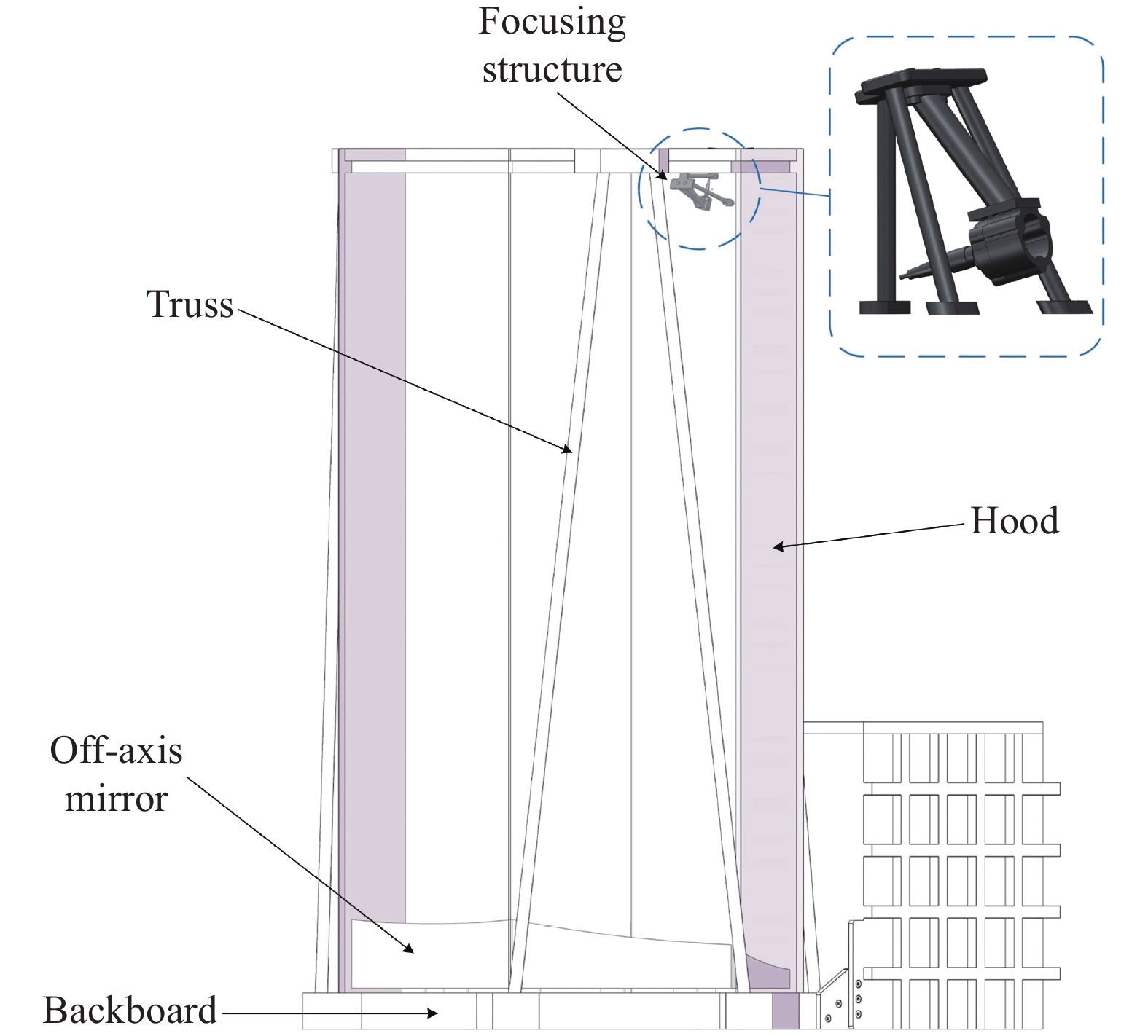
通过上述设计确定了激光雷达主镜的结构,将桁架、遮光板、光纤座等组件加入模型后,确定了其整体结构。为了简化计算量,对光学组件模型做了部分简化,去除了信号接收端的电子元件和其外部细节。简化后的研究模型如图5所示。

图 5 天线整体结构
Figure 5. Overall antenna structure
-
文中使用的仿真软件为ANSYS,根据激光雷达实际工况,飞艇可以长期稳定地在临近空间运行,激光雷达分析环境可视作在稳态温度场,激光雷达温度场的几何条件为激光雷达的整体几何模型,边界条件主要考虑两种,即恒温边界条件和热传导边界条件[19]。激光雷达的工作环境为临近空间,虽然空间环境复杂,但是由于其温度较为稳定,温度场设置与需要分析的运行高度有关,根据不同大气模型温度分布趋势图以及文中激光雷达的工作高度为20 km以上的临近空间,可将温度选择为−60~−20 ℃,温度条件按照分析步骤以5℃为间隔,依次对−60~−20℃进行热分析。激光雷达的工况为−60 ℃,它与环境产生热交换,其部件产生温度变化。固定约束选择在了电子元件箱的侧面,边界位置选择在了与反射镜组件关联较小的位置,这样镜面的热变形不会受到约束位置的影响,能够获得更准确的变形数据。设置完分析条件后,需要对有限元模型进行网格划分,反射镜部分使用有10个节点的四面体单元(Tet10),网格尺寸为3 mm,并对反射镜镜面进行面网格剖分,使网格更加平滑整齐。Tet10是一种高阶四面体单元类型,具有更高的计算准确度,能够更好地应对复杂几何形状和边界条件,适用于对结构进行更精确的分析和计算。其余组件部分不是分析重点,网格尺寸为10 mm。得到最终整体网格的平均网格质量为0.82,平均雅可比比率为0.99,网格质量满足分析要求。通过有限元分析软件可以得出天线整体的变形情况,如图6所示。

图 6 整体结构热变形
Figure 6. Thermal deformation of the overall structure
由于所用材料的热膨胀系数较小,温度变化导致机械结构和反射镜的最大位移量为0.2822 mm,无法看出镜面的变化趋势。为了直观地观察到反射镜的变化趋势,将图像的变形比例因子适当提高后,得到的抛物面反射镜变形情况如图7所示。
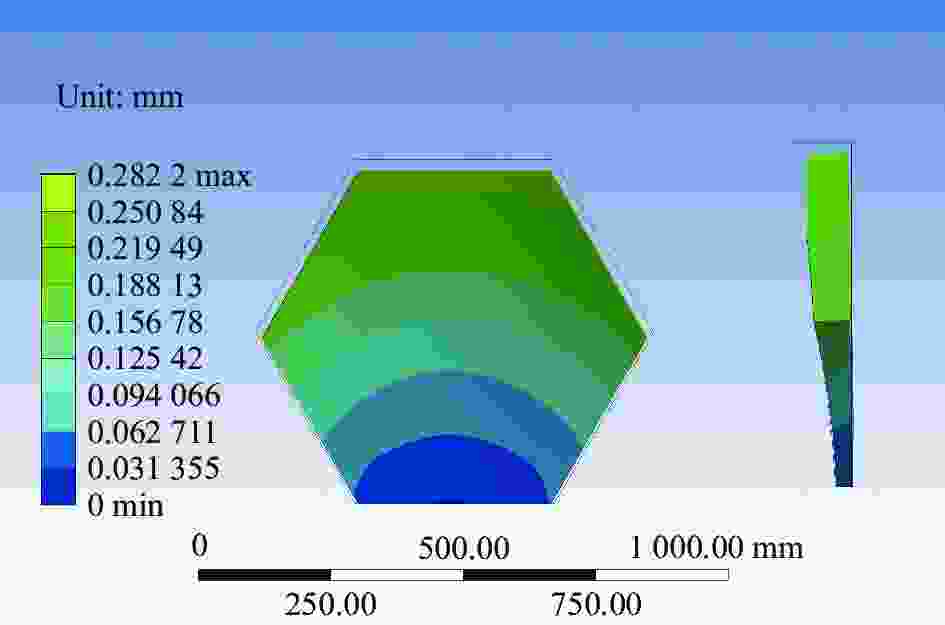
图 7 抛物面反射镜热变形
Figure 7. Thermal deformation of parabolic mirror
分析流程如下:首先,通过有限元分析软件对激光雷达进行热变形仿真,得到光学表面基于节点的位移数据;其次,根据得到的节点位移数据进行Zernike多项式拟合,得到基于光学理论的反射镜热变形面形;最后,利用光学软件对其进行评价。光学表面变形包括散焦、偏心、倾斜和表面变形四种形式[20]。在激光雷达中,造成反射镜离焦、偏心、倾斜的原因是由支撑装置和反射镜变形造成的。反射镜这种位移通常被称为刚体位移,而激光雷达中反射镜表面的面畸变主要由光学镜组的内部应力造成,其变形后的光学表面点列图和光纤耦合效率如图8所示。
从图8中可以看出,在不改变接收面位置的情况下,不同温度下光纤端面光斑的变化趋势,其点列图半径随着温度的降低而增大,反射镜的光学性能受到温度变形的影响明显,在−60 ℃时耦合效率降低至15.784%。仿真实验表明,激光雷达在温度变化后产生的热变形会导致光纤耦合效率降低。为了减小热变形对耦合效率的影响,通过使用光学设计软件,根据激光雷达机械结构调整接收端面位置,以找到面形变化后的最佳焦平面位置。优化后的接收端面点列图和光纤耦合效率如图9所示。

图 8 未调整成像位置前的点列图
Figure 8. Spot diagram before adjusting the imaging position

图 9 调整成像位置后的点列图
Figure 9. Spot diagram after adjusting the imaging position
从图9中可以看出,在光学设计软件里找到最佳像面后,能够有效提升激光的耦合效率。像面移动后,激光光源能打在光纤端面上,减小了RMS半径,使耦合效率提升到91%。
通常飞艇在临近空间的工作时间较长,使得激光雷达的温度和环境温度能够保持一致并达到热平衡。临近空间的温度随高度的升高而变高,因此分析了激光雷达在−60~−20℃下的最佳像面位置,提高其在飞艇不同航行高度下的耦合效率。图10显示了不同温度下的最佳像面位置相对于初始位置(0, 0)的坐标位置。
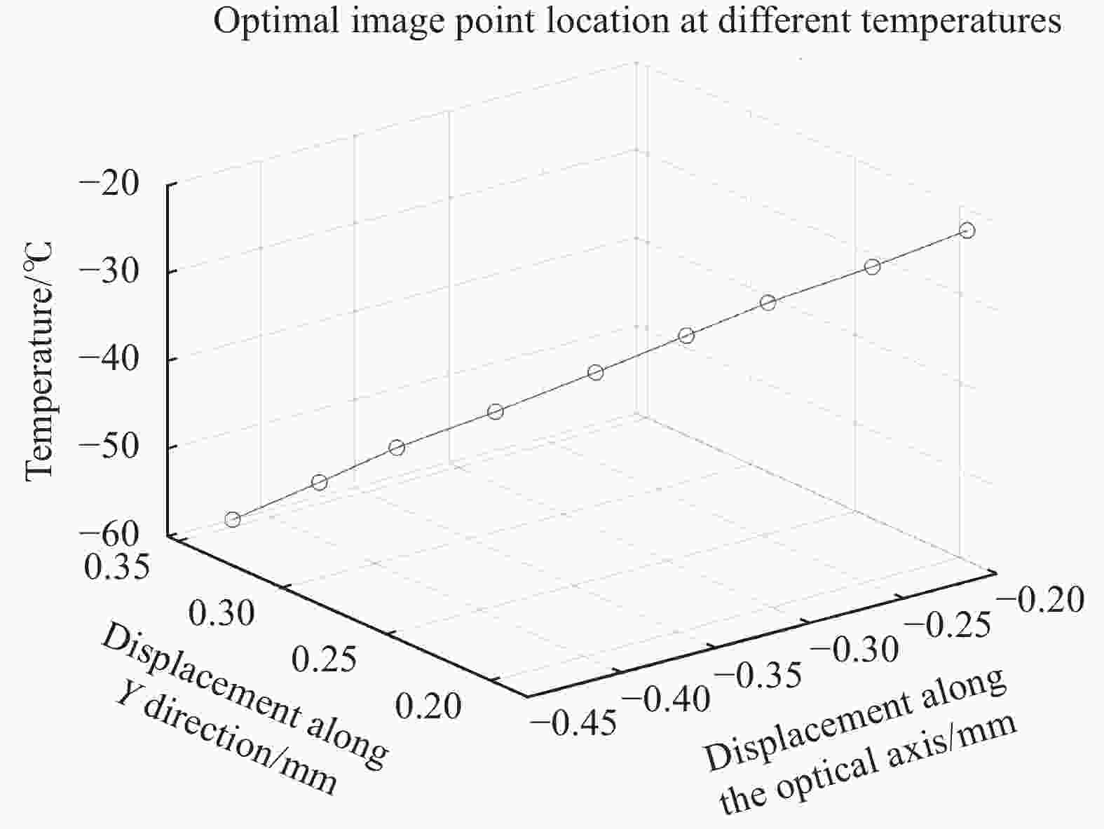
图 10 最佳像面中心点位置曲线
Figure 10. Optimal image surface center position curve
-
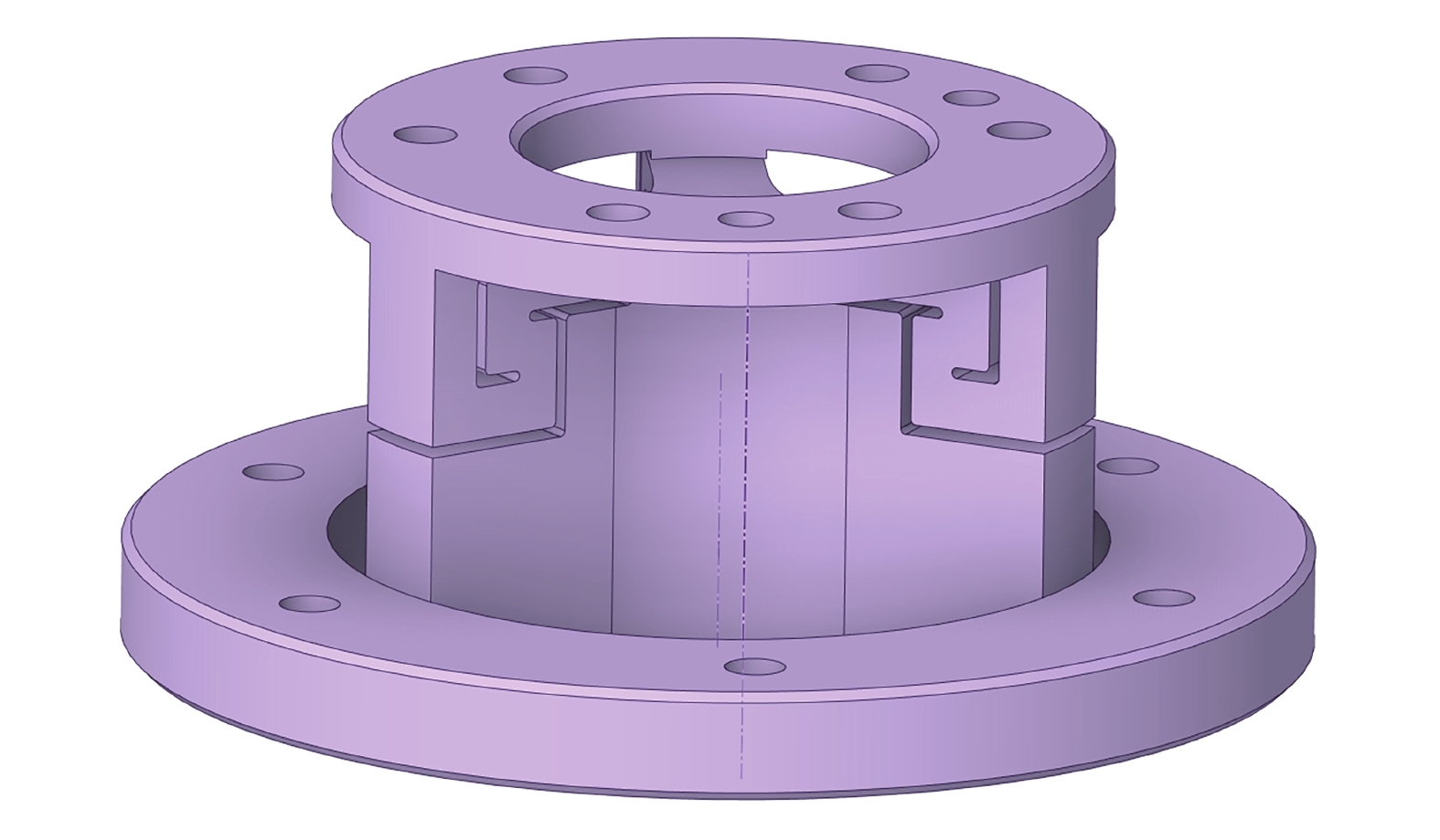
由图10可知,最佳焦点位置的变化规律接近直线,当温度为−60 ℃时,焦点移动的直线距离为0.546 mm,因此,可使用物体线膨胀值接近该趋势的材料来代替电机调整光纤端面位置。所设计的光纤固定结构如图10所示。
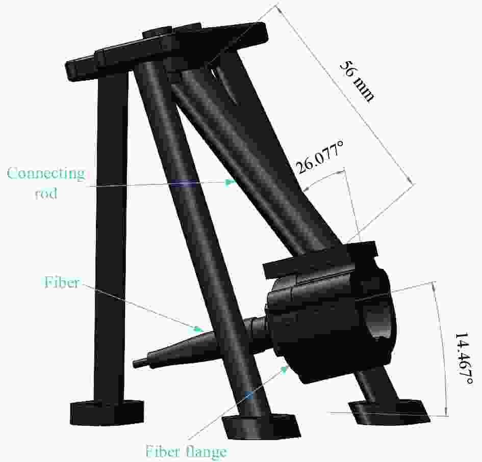
图 11 光纤固定结构示意图
Figure 11. Schematic diagram of fiber optic holder structure
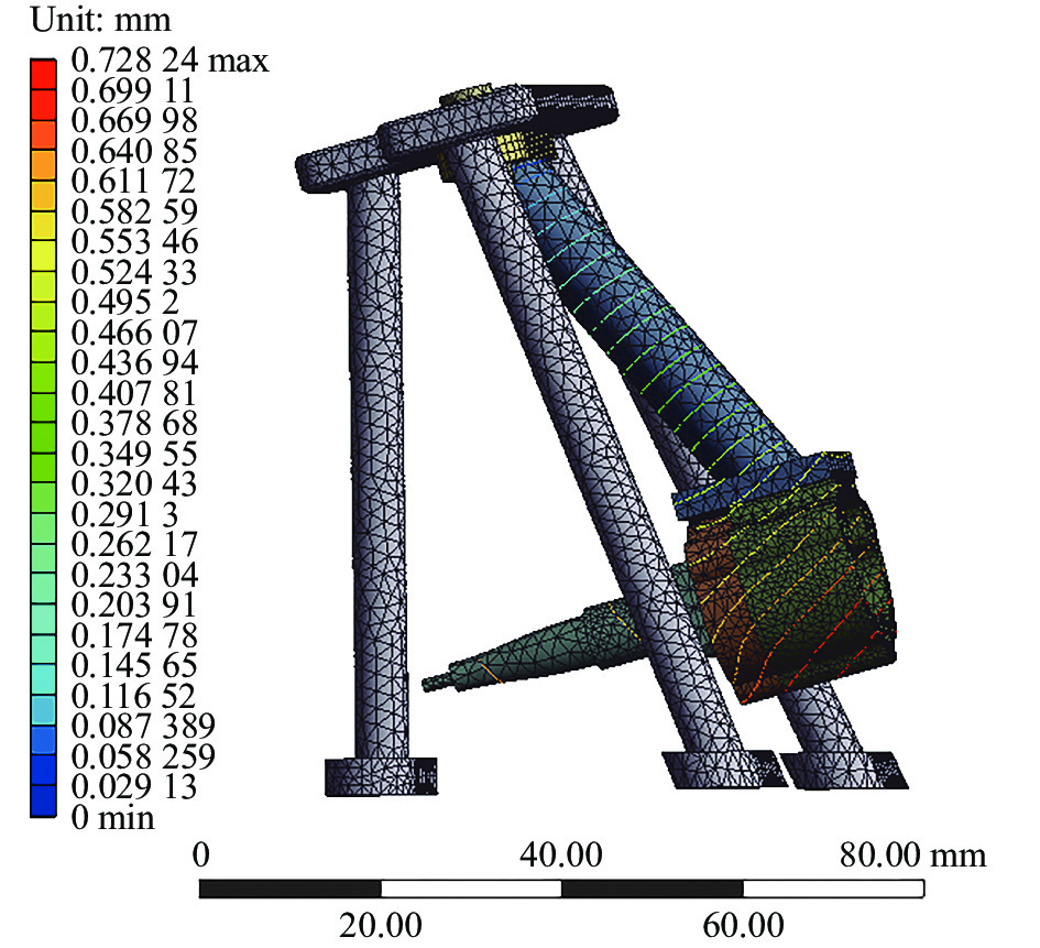
图11中,光纤架连接杆选用聚四氟乙烯(Polytetrafluoroethylene,PTFE)作为主体材料,该材料具有良好的耐寒性,可在−180 ℃工作;具有一定的耐辐射性,太阳辐射对它几乎没有影响。PTFE的线膨胀系数α=120×10−6 K−1,光纤端中心点至连接端的长度为56 mm,通过热膨胀计算公式可求得其在−60 ℃下的变形量为0.551 mm,与最佳焦点位置相差0.005 mm,几乎不会对光斑质量造成影响。其余零部件材料均为CFRP,其热膨胀系数远小于PTFE。其中,光纤安装座的倾角为−14.467°,为反射光中心光与光纤端面的夹角;安装座固定杆倾角为−40.544°,为焦点移动曲线的倾斜角。对光纤固定结构进行热仿真分析,分析结果如图12所示。

图 12 光纤座热分析图
Figure 12. Thermal analysis diagram of fiber optic holder
从图12中可以看出,光纤安装孔中心在−60 ℃下的热变形量约为0.553 mm,与公式所求变形量相差0.002 mm,接近一致。将该结构与天线遮光板连接,分析获得其在不同温度下的耦合效率。通过热补偿机构自动补偿至不同温度对应位置,其均方根半径小于优化前的系统。对未移动像面和自适应补偿后像面处的耦合效率进行对比,得到的耦合效率对比图如图13所示。可以看出,耦合效率随着温度降低从90%下降至15.7%,接收能量过低,难以满足系统需求。通过自动调焦装置调整光纤端面后,在−60 ℃的最低温工况下,耦合效率可以达到78%,其余工况下耦合效率均高于80%,满足系统需求。

图 13 耦合效率对比图
Figure 13. Coupling efficiency comparison chart
-
通过有限元分析,发现天线的热变形会使抛物面反射镜表面形状和机械结构产生形变,导致光纤耦合效率降低。文中设计的激光雷达主镜组件,其最佳焦点位置与温度关系近似直线,使用机械结构自身的热膨胀特性,使其在不同温度下的热变形量将光纤移动到最佳像面位置,有效地减小了激光光斑尺寸,使激光雷达在−20~−60 ℃的环境温度下耦合效率均高于78%,提高了激光雷达在低温条件下的工作稳定性和可靠性,为研究者们提供了有价值的数据,文中采用的方法也适用于其他参数反射镜以及同轴反射镜。
Design of automatic out-of-focus correction system for near-space lidar receivers
-
摘要: 针对临近空间激光雷达所使用的离轴抛物面反射镜在低温下会发生形变导致反射光耦合进光纤时效率下降的问题,通过研究自调焦技术,设计了自动补偿激光雷达组件,用于抵消温度对系统的影响。利用有限元法分析了接收系统在热载荷作用下的变形,获得镜面离散变形数据,使用Zernike多项式拟合镜面变形后的面形,通过光学设计软件模拟得出该激光雷达接收系统优化后的焦距变化与温度呈线性关系,经过光学设计软件确定补偿位置。使用温度自适应调整机构降低热变形带来的离焦量影响。分析结果表明,补偿后均方根半径从26.495 μm下降至15.93 μm,光斑半径减少39.9%,耦合效率提升至80%以上。Abstract:
Objective Lidar is the main way to obtain three-dimensional geographic information within the military, and the data results obtained through this way are also widely used in resource exploration, land use, environmental monitoring and national key construction projects, providing extremely important original information for the national economy, social development and scientific research, and has achieved significant economic benefits, showing good application prospects. The lower temperature of the near space can reach –60 ℃, the optical antenna as the core component of LiDAR, its optical components have strict requirements for temperature changes. Temperature variations can lead to thermal deformation of the element, resulting in problems of defocusing and focal plane translation, which reduces the coupling efficiency. Improving the coupling efficiency can increase the detection rate, and the off-axis reflective optical system can be realized without obstruction, which can improve the energy utilization. However, unlike conventional refractive or coaxial reflection systems, each optical element in the off-axis reflection system does not have rotational symmetry, and its temperature deformation after temperature change is not uniform, so solving the effect of temperature change on the focus of the off-axis parabolic mirror is the key to improve the coupling efficiency of LiDAR. Methods In this paper, the LiDAR is modeled, and the temperature field is simulated by the finite element analysis method for the model. The Zernike polynomials are used to fit the surface shape data obtained after the analysis to obtain the shape and position change of the reflector after temperature deformation, and the optical design software is used to obtain the optimal focal point position. Finally, the optical fiber position is adjusted by the focusing device to achieve the effect of focusing. Results and Discussions The PV value of the mirror of the designed LiDAR is less than 10/λ. Its optimal focus position curve is obtained by optical design software, and a temperature-adaptive focusing structure is designed according to this curve, through which the RMS radius of the mirror compensated by the focusing structure decreases from 26.495 μm to 15.93 μm, the spot radius is reduced by 39.9%, and the coupling efficiency is improved from 15.8% to 91%. This focusing method does not need to keep track of the changes in the temperature of the reflector and reduces a certain amount of weight and cost compared to focusing with a motor. However, the method requires a certain temperature response time, can not adjust the focus to the best position at the first time after the temperature change. If the temperature changes frequently, the motor should be used to quickly adjust. Due to the working height of the blimp is more fixed, and its ambient temperature does not change much, the method is feasible. Conclusions Aiming at the problem that the off-axis parabolic mirrors used in the near-space lidar will deform at low temperatures which leads to a decrease in the efficiency of the reflected light when it is coupled into the optical fiber, the self-focusing technique is investigated, and the auto-compensating lidar assembly is designed to offset the effect of temperature on the system. The deformation of the receiving system under thermal load is analyzed using the finite element method to obtain the discrete deformation data of the mirror surface, and the Zernike polynomials are used to fit the surface shape after the deformation of the mirror surface, and the simulation of the optical design software concludes that the change of the focal length of this LiDAR receiving system after optimization has a linear relationship with the temperature, and the compensation position is determined by the optical design software. A temperature adaptive adjustment mechanism is used to reduce the effect of out-of-focus amount caused by thermal deformation, which improves the coupling efficiency by more than 80%. -
图 1 不同大气模型温度分布趋势
Figure 1. Temperature distribution trends of different atmospheric models
图 2 不同材料组合在−60 ℃下的光学性能对比
Figure 2. Comparison of optical properties of different material combinations at −60 ℃
表 1 反射镜常用材料属性
Table 1. Properties of commonly used materials for mirrors
Material Density
ρ/kg·m–3Elasticity
modulus
E/GPaThermal
conductivity
Kcc/W·m–1·℃–1Thermal
Expansion
α/K−1Poisson
ratio
νSiC 3200 400 270 2.5×10⁻⁶ 0.18 Al/SiC 3010 215 210 7.9×10⁻⁶ 0.2 K9 2510 81 1.21 7.5×10⁻⁶ 0.21 Zerodur 2500 92 1.46 0.05×10⁻⁶ 0.24 Fused Silica 2201 74 1.38 5.6×10⁻⁷ 0.17 TC4 4440 114 6.8 9.1×10⁻⁶ 0.34 ZTC4 4400 112 8.8 8.9×10⁻⁶ 0.29 4J32 810 138.2 14.7 2.4×10⁻⁶ 0.25 CFRP 1480 9-91.82 9.68 0.5×10⁻⁶ 0.05-0.3  下载: 导出CSV
-
[1] 谭玉凤, 王继红, 任戈, 等. 大口径主镜热边界层热控对成像质量影响分析 [J]. 红外与激光工程, 2018, 47(12): 1218005. Tan Yufeng, Wang Jihong, Ren Ge, et al. Effect of thermal control of thermal boundary layer on image quality with large-aperture primary mirror [J]. Infrared and Laser Engineering, 2018, 47(12): 1218005. (in Chinese) [2] Haber A, Draganov J, Heesh K, et al. Modeling, experimental validation, and model order reduction of mirror thermal dynamics [J]. Optics Express , 2021, 29(15): 24508-24524. [3] 潘翔. 抛物面天线热补偿系统的设计与实现[D]. 西安: 西安电子科技大学, 2022. [4] Kaifler B, Rempel D, Roßi P, et al. A technical description of the Balloon Lidar Experiment (BOLIDE) [J]. Atmospheric Measurement Techniques, 2020, 13(10): 5681-5695. doi: 10.5194/amt-13-5681-2020 [5] 管雯璐, 谭逢富, 靖旭, 等. 基于环境温度反馈的卡塞格林望远镜自动调焦 [J]. 光学精密工程, 2021, 29(8): 1832-1838. doi: 10.37188/OPE.20212908.1832 Guan Wenlu, Tan Fengfu, Jing Xu, et al. Automatic focusing of Cassegrain telescope based on environmental temperature feedback [J]. Optics and Precision Engineering, 2021, 29(8): 1832-1838. (in Chinese) doi: 10.37188/OPE.20212908.1832 [6] 汤伟, 刘立生, 刘扬, 等. 激光空间合束主镜优化设计与分析 [J]. 中国光学, 2020, 13(3): 442-450. Tang Wei, Liu Lisheng, Liu Yang, et al. Optimization and analysis of a primary mirror for a laser incoherent combining system [J]. Chinese Optics, 2020, 13(3): 442-450. (in Chinese) [7] 程旋, 杨钧烽, 张依鸣, 等. 临近空间大气经验模型研究现状及在中国区域的适用性评估 [J]. 空天技术, 2023(1): 1-12. Chen Xuan, Yang Junfeng, Zhang Yiming, et al. Research on advance in empirical atmospheric models of near space and assessment of applicability in China [J]. Aerospace Technology, 2023(1): 1-12. (in Chinese) [8] 李蕾. 基于Zernike矢量多项式的离轴反射系统装调技术研究[D]. 中国科学院大学(中国科学院长春光学精密机械与物理研究所), 2020. Li Lei. Alignment technique for off-axis reflective systems based on zernike vector polynomials [D]. Changchun: University of Chinese Academy of Sciences (Changchun Institute of Optics, Fine Mechanics and Physics, Chinese Academy of Sciences), 2020. (in Chinese) [9] Wang J, Silva D. Wave-front interpretation with Zernike polynomials [J]. Appl Opt, 1980, 19: 1510-1518. doi: 10.1364/AO.19.001510 [10] Zernike von F. Beugungstheorie des schneidenver-fahrens und seiner verbesserten form, der phasenkontrastmethode [J]. Physica, 1934, 1(7-12): 689-704. doi: 10.1016/S0031-8914(34)80259-5 [11] Malacara-Hernandez D, Carpio-Valadez M, Sanchez-Mondragon J J. Wavefront fitting with discrete orthogonal polynominals in a unit radius cycle [J]. Optical Engineering, 1990, 29(6): 672-675. doi: 10.1117/12.55629 [12] 王增伟, 赵知诚, 杨溢, 等. 基于刚体运动完备方程的光机热集成分析方法 [J]. 红外与激光工程, 2022, 51(6): 20210617. Wang Zengwei, Zhao Zhicheng, Yang Yi, et al. Thermal-structural-optical integrated analysis method based on the complete equations of rigid body motion [J]. Infrared and Laser Engineering, 2022, 51(6): 20210617. (in Chinese) [13] ZEMAX. Optical Design Program User’s Manual [Z]. Version 7.1. 2011: 115-119. [14] 屈金祥. Zernike 多项式及其在低温光学中的应用[A]. 上海市制冷学会2005年学术年会论文集[C]. 2005: 1220. Qu Jinxiang. Zernike polynomial and its use in cryogenic optics [C]//Proceedings of the 2005 Annual Meeting of Shanghai Refrigeration Society, 2005: 1220. (in Chinese) [15] 廖延彪, 黎敏. 光纤光学[M]. 北京: 清华大学出版社, 2013. [16] Friedman E, Miller J L. Photonics Rules of Thumb[M]. 2nd ed. New York: McGraw-Hill, 2003. [17] 武永见, 刘涌, 孙欣. 柔性支撑式空间反射镜胶接应力分析与消除 [J]. 红外与激光工程, 2022, 51(4): 20210496-1-20210496-5. Wu Yongjian, Liu Yong, Sun Xin. Analysis and elimination of adhesive bonding force of flexible supported space mirror [J]. Infrared and Laser Engineering, 2022, 51(4): 20210496. (in Chinese) [18] 陆煜, 程林. 传热原理与分析[M]. 北京: 科学出版社, 1997. [19] Faria J, Alves J L, Nunes-Pereira E J. Comparison of lenses' thermal expansion formulation in Zemax versus ANSYS with SigFit post processing [C]//Optomechanical Engineering, SPIE, 2017, 10371: 1037101. [20] Yoder Jr P R. Opto-Mechanical Systems Design[M]. Boca Raton: CRC Press, 2005. -

 点击查看大图

图(13) / 表(1)
计量
- 文章访问数: 28
- HTML全文浏览量: 6
- PDF下载量: 7
- 被引次数: 0

