


-
四象限探测器通过测量目标相对于导引头光轴的光束偏转角从而实现其对目标的视线跟踪,所以四象限探测器测角精度直接影响激光武器的跟踪精度,因此研究探测器测角精度十分重要。就研究现状来看,参考文献[1]研究了当理想电压在时域上服从高斯分布时,通过仿真实验得出了光斑中心在光敏面五个不同位置处的光束俯仰角统计分布规律;参考文献[2][3]定性分析了当光斑中心与光敏面中心重合时,不同参数对四象限探测器测角精度的影响;参考文献[4-8]研究了四象限探测器的位移测量标定方法;参考文献[9][10]研究了当光敏面上的光斑信号服从高斯分布时,不同参数对四象限探测器位置检测精度的影响;参考文献[11][12]分析了采用对角线相减式测角方法的激光导引头角跟踪误差的计算方法。
但由于目前激光导引头普遍采用和差比幅式的测角方法,且对于半主动激光制导来讲,经目标漫反射到达导引头入瞳处的脉冲能量趋近于均匀分布,为深入研究在该情况下的四象限探测器测角精度,文中从计算分析的方法出发,在半主动激光制导方式下,分析了四象限探测器对目标的测角原理,基于导引头入瞳处脉冲峰值功率密度服从均匀分布,噪声干扰电流服从高斯分布,建立了激光导引头光束偏转角误差模型;由于工程应用更关注四象限探测器测角范围以及漫反射激光以特定入射角进入导引头光学系统时的四象限探测器测角精度,所以将光束偏转角误差的均值和标准差作为探测器测角精度的衡量标准,分别建立了光束偏转角误差的均值和标准差与导引头光学系统参数、光斑半径、漫反射激光入射角、噪声干扰电流以及导引头入瞳处脉冲峰值功率密度之间的关系,并以光束方位角误差标准差为例,结合应用背景量化分析了不同参数对光束方位角误差标准差的影响。
-
经目标漫反射的激光信号进入导引头后,将在探测器光敏面上形成光斑信号,四个光电二极管根据光斑信号在各象限内的功率输出电流,经A/D转换、信号放大后产生电压信号,四象限探测器依据采用的测角方法分别在二维坐标系
$x$ 轴、$y$ 轴上产生偏差分量,导引头信息处理系统依据预先通过试验拟合的偏差分量与光斑中心坐标的关系得出光斑中心坐标,而后根据光斑中心坐标确定目标相对于导引头光轴的方位角和俯仰角,进而根据导引头光学系统、探测器与弹体间的耦合方式,通过控制光学系统、探测器或弹体运动,使导引头和目标连线与导引头光轴重合,实现激光导引头对目标的视线跟踪。制导激光是经目标漫反射进入导引头光学系统的,所以其在光敏面上形成光斑的功率密度趋近于均匀分布,现假设光斑功率密度为
${\rho _s}$ ,制导激光引起各象限光电二极管输出的电流为${I_i}(i = A,B,C,D)$ ,则:式中:
${R_p}$ 为探测器脉冲响应率($\rm{A/W}$ );${S_i}$ 为光斑在光敏面各象限内的面积。对电流信号进行电流/电压转换并进行放大,记转换系数为
${R_{A \to V}}$ ,放大系数为${K_1}$ ,则:公式(2)中,
${U_i}$ 表示制导激光引起的四象限探测器$i$ 象限输出的电压。当各象限输出电压为
${U_i}(i = A,B,C,D)$ 时,则坐标系$x$ 轴、$y$ 轴的偏差分量$\Delta x$ 、$\Delta y$ 为:激光制导中的光斑中心坐标
${x_0},{y_0}$ 与偏差分量$\Delta x,\Delta y$ 的关系是通过试验标定得到的,由于试验标定的关系不易获得,所以通过理论研究光斑中心坐标${x_0},{y_0}$ 与偏差分量$\Delta x,\Delta y$ 的关系。将公式(1)、(2)代入公式(3)得:式中:
${S_A}$ 、${S_B}$ 、${S_C}$ 、${S_D}$ 分别表示光斑在光敏面对应象限内的面积。当光斑中心在光敏面
${{A}}$ 象限时,偏差分量$\Delta x$ 的计算分析原理图如图1所示。
Figure 1. Schematic diagram of calculation and analysis of deviation components
$\Delta x$ 图1中,
$R$ 表示光敏面半径,$r$ 表示光斑半径,${x_0},{y_0}$ 表示光斑中心坐标。${S_{s(aobc)}}$ 表示扇形$aobc$ 的面积,${S_{s(aobd)}}$ 表示扇形$aobd$ 的面积,${S_{\Delta (aob)}}$ 表示三角形$aob$ 的面积,则:所以,
${S_A} + {S_D}$ 与${S_B} + {S_C}$ 可表示为:所以,
$\Delta x,\Delta y$ 表达式为:激光制导过程中,并不是根据偏差分量
$\Delta x,\Delta y$ 反求光斑中心坐标${x_0},{y_0}$ ,而是通过试验标定拟合出${x_0},{y_0}$ 与$\Delta x,\Delta y$ 的关系(近似线性),进而在已知$\Delta x,\Delta y$ 条件下,求解${x_0},{y_0}$ 。为方便研究,利用公式(7)泰勒展开式线性部分代替试验标定${x_0},{y_0}$ 与$\Delta x,\Delta y$ 的关系,则:当已知光斑中心坐标
${x_0},{y_0}$ 时,信息处理系统将生成光束俯仰角$\theta $ 和方位角$\psi $ ,其中光束偏转角与光斑中心坐标的关系如图2所示。
Figure 2. Relationship between beam deflection angle and center coordinates of spot
以光学透镜中心为坐标原点
$o$ ,以导引头光轴为$z$ 轴,垂直导引头光轴向上为$y$ 轴,按照右手螺旋关系确定$x$ 轴,则绕$y$ 轴转动产生光束方位角$\psi $ ,光束方位角$\psi $ 以$y$ 轴负向为正,绕$x$ 轴转动产生光束俯仰角$\theta $ ,光束俯仰角$\theta $ 以$x$ 轴正向为正,现坐标系$o - xyz$ 按照先方位角后俯仰角的顺序转动,则:由于
${x_0} \ll {f_{\rm{x}}}$ ,则公式(9)可近似为:式中:
$\psi ,\theta $ 分别为导引头光束方位角和光束俯仰角,称为光束偏转角;${f_{\rm{x}}}$ 为光学透镜中心与光敏面中心的距离。 -
实际制导过程中,光电二极管输出电流不仅与制导激光有关,还受太阳背景光、热噪声、暗电流等因素影响,记各象限输出的总噪声干扰电流分别为
${i_A},{i_B},{i_C},{i_D}$ ,由于噪声电流相比制导激光引起的电流十分微弱,所以仍可将光敏面上光斑信号功率密度当作均匀分布处理,即偏差分量$\Delta x,\Delta y$ 与光斑中心坐标${x_0},{y_0}$ 仍满足公式(8),则考虑噪声干扰电流下的激光导引头光束偏转角表达式为:式中:
${\psi _N},{\theta _N}$ 为考虑噪声的光束方位角和光束俯仰角。将光束方位角误差记为$\Delta \psi $ ,光束俯仰角误差记为$\Delta \theta $ ,则:由于光束偏转角误差
$\Delta \psi ,\Delta \theta $ 与噪声干扰电流${i_A},{i_B},{i_C},{i_D}$ 是非线性关系,且噪声干扰电流${i_A},{i_B},{i_C},{i_D}$ 为随机误差,因此不易讨论${i_A},{i_B},{i_C},{i_D}$ 对$\Delta \psi ,\Delta \theta $ 的影响,需对公式(12)进行线性等效,令${I_i} + {I_j} = {I_{ij}}$ ,${i_i} + {i_j} = {i_{ij}}$ ,则公式(12)等效为:将
${I_{ij}}$ 看作定量,${i_{ij}}$ 看作微小增量,对$\Delta \psi ,\Delta \theta $ 进行二元泰勒展开且仅取线性部分,则:式中:
${E_\psi }$ 为光束方位角偏差的近似值;${E_\theta }$ 为光束俯仰角偏差的近似值。 -
光束偏转角误差
${E_\psi },{E_\theta }$ 取值具有随机概率性,其大小与制导激光引起的输出电流以及噪声干扰电流有关。假设各象限的总噪声干扰电流${i_A},{i_B},{i_C},{i_D}$ 相互独立且均服从$\left(\dfrac{\mu }{4},\dfrac{{{\sigma ^2}}}{4}\right)$ 的高斯分布,则光束偏转角误差${E_\psi },{E_\theta }$ 也服从高斯分布,其均值和标准差表达式为:式中:
$E({E_\psi })$ 为光束方位角误差${E_\psi }$ 的均值;$E({E_\theta })$ 为光束俯仰角误差${E_\theta }$ 的均值;$\sigma ({E_\psi })$ 为光束方位角误差${E_\psi }$ 的标准差;$\sigma ({E_\theta })$ 为光束俯仰角误差${E_\theta }$ 的标准差;$\sigma $ 为四个光电二极管输出总噪声干扰的电流标准差。在激光制导中,更加关注四象限探测器的测角范围以及四象限探测器对进入导引头光学系统的不同漫反射激光入射角的测角精度。通常,物镜半径、焦距是固定值,所以应考虑光斑半径和漫反射激光入射角对测角范围和测角精度的影响,记导引头入瞳处制导激光的脉冲峰值功率密度为
${P_s}$ ,则:式中:
${S_s}$ 为导引头入瞳处面积;$T$ 为导引头光学系统透过率。假设光斑在焦平面之前成像,则透镜中心与光敏面距离${f_x}$ 、光斑中心坐标${x_0},{y_0}$ 、光斑半径$r$ 、漫反射入射角${\psi _f},{\theta _f}$ 之间满足如下关系:式中:
$\Delta f$ 为离焦量;$f$ 为焦距;${R_t}$ 为物镜半径。将公式(6)、(7)、(16)、(17)代入公式(15),则:式中:
$SNR = \dfrac{{{P_s} \cdot {S_s} \cdot T \cdot {R_{\rm{P}}}}}{\sigma }$ ,记$SNR$ 为信噪比。通常光束偏转角实际值相比理想值偏小,通过增大目标指示器单脉冲能量等方法可使光束偏转角误差减小。由于$E({E_\psi })$ 与$E({E_\theta })$ 、$\sigma ({E_\psi })$ 与$\sigma ({E_\theta })$ 分别相对于$y = x$ 对称,因此仅需研究$E({E_\psi })$ 和$\sigma ({E_\psi })$ ,又因为$E({E_\psi })$ 和$\sigma ({E_\psi })$ 的分析基本相同,因此,结合应用背景以$\sigma ({E_\psi })$ 为例进行分析。 -
当
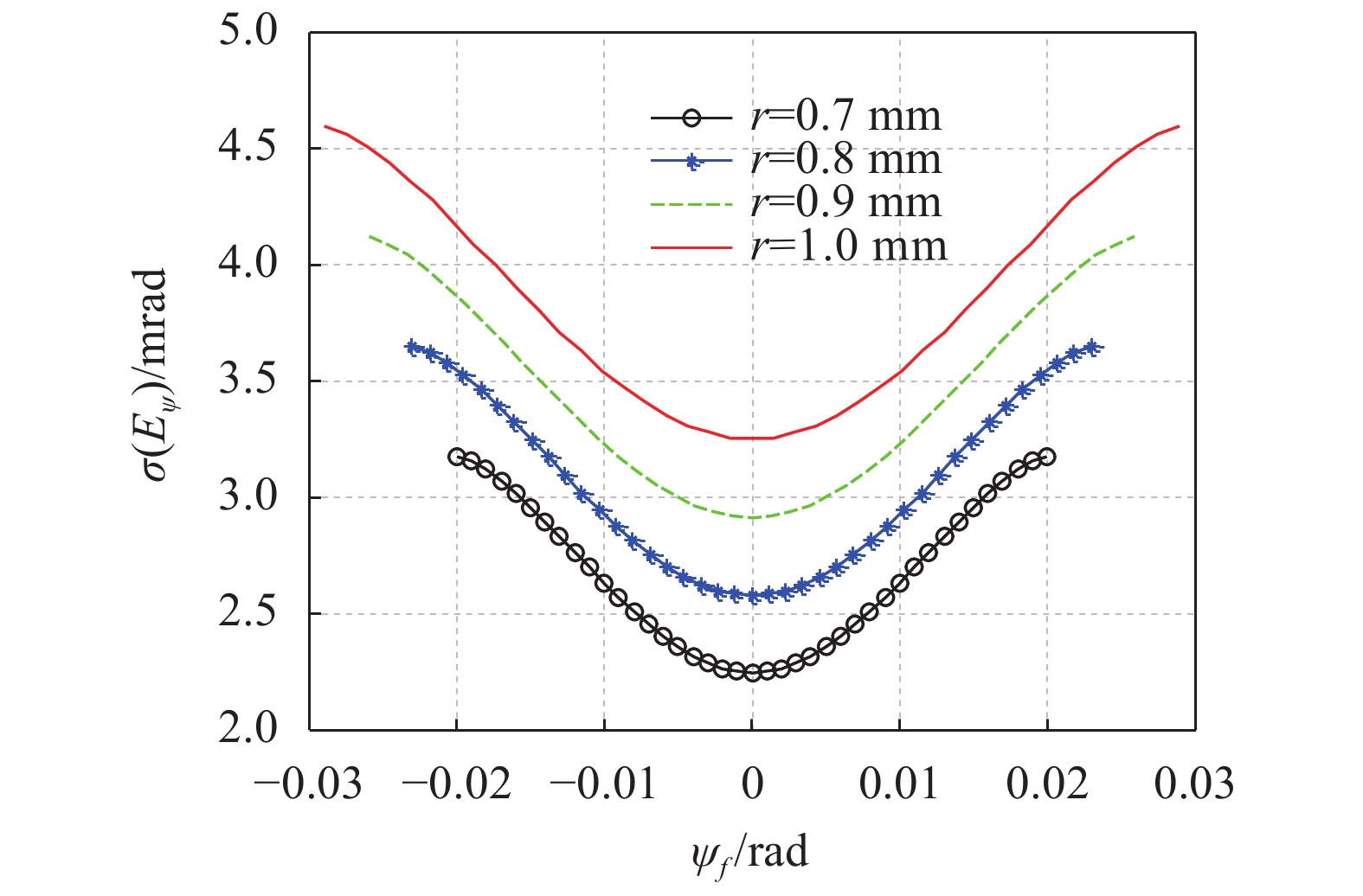
$f = 36\;{\rm{mm}}$ ,${R_t} = 25\;{\rm{mm}}$ ,$SNR = 7$ ,光斑半径分别取$r = 0.7\; {\rm{mm}}{\text{,}}0.8\; {\rm{mm}}{\text{,}}0.9\; {\rm{mm}}{\text{,}}1\; {\rm{mm}}$ 时,通过MATLAB仿真$\sigma ({E_\psi })$ 与${\psi _f}$ 的关系如图3所示。
Figure 3. Relationship between
$\sigma ({E_\psi })$ and${\psi _f}$ 为更好地分析入射角
${\psi _f}$ 对方位角误差标准差$\sigma ({E_\psi })$ 的影响,根据仿真结果得表1。$\sigma ({E_\psi })$/mrad ${\psi _f}$/rad 0 0.005 0.01 0.015 0.02 r=0.7 mm 2.2445 2.3532 2.6280 2.9541 3.1742 r=0.8 mm 2.5758 2.6716 2.9236 3.2482 3.5453 r=0.9 mm 2.9097 2.9952 3.2263 3.5404 3.8634 r=1 mm 3.2465 3.3236 3.5360 3.8358 4.1659 Table 1. Relationship between
$\sigma ({E_\psi })$ and${\psi _f}$ 由图3知,方位角误差标准差
$\sigma ({E_\psi })$ 关于入射角${\psi _f} = 0$ 对称,当光斑半径$r$ 一定时,$\sigma ({E_\psi })$ 随着${\psi _f}$ 增大而增大,若${\psi _f} = 0$ ,$\sigma ({E_\psi })$ 取最小值,即激光导引头在锁定跟踪阶段,四象限探测器测角精度最大。由表1知,当$r = 1\;{\rm{mm}}$ 时,若${\psi _f} = 0.01\;{\rm{rad}}$ ,则$\sigma ({E_\psi }) = 3.536\;{\rm{mrad}}$ ,即漫反射激光以0.01 rad的角度进入导引头,则方位角误差标准差为3.536 mrad;而若${\psi _f} = 0$ ,则$\sigma ({E_\psi }) = $ 3.246 5 mrad,即激光导引头跟踪上目标时,方位角误差标准差约为3.246 5 mrad。当入射角${\psi _f}$ 一定时,$\sigma ({E_\psi })$ 随着$r$ 增大而增大,即增大光斑半径$r$ 会使方位角误差标准差$\sigma ({E_\psi })$ 增大,所以可通过调节导引头光学系统结构减小光斑半径,进而提高四象限探测器测角精度,但是光斑半径$r$ 减小,导引头视场范围也减小,所以在光学系统设计中,要综合四象限探测器测角精度和视场范围确定光斑半径以及光敏面半径。 -
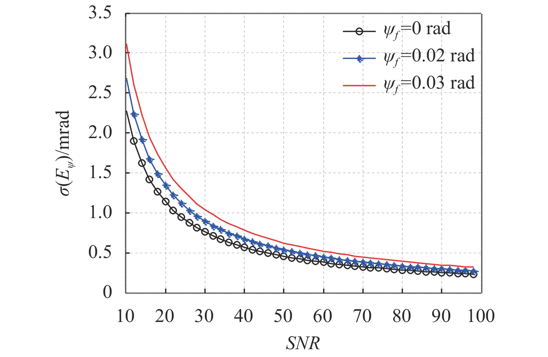
激光制导过程中,从激光导引头探测到制导信号至导引头进入盲区,信噪比
$SNR$ 逐渐增大。当f = 36 mm,Rt = 25 mm,r = 1 mm,${\psi _f}$ 分别取${\psi _f} = $ 0 rad, 0.02 rad, 0.03 rad时,通过MATLAB仿真$\sigma ({E_\psi })$ 与$SNR$ 的关系如图4所示。
Figure 4. Relationship between
$\sigma ({E_\psi })$ and$SNR$ 为更好地分析信噪比
$SNR$ 对方位角误差标准差$\sigma ({E_\psi })$ 的影响,根据仿真结果得表2。$\sigma ({E_\psi })$/mrad SNR 10 30 50 70 90 ${\psi _f} = 0\;$ 2.272 6 0.757 5 0.4545 0.3247 0.2525 ${\psi _f} = 0.02\;$ 2.684 9 0.895 0 0.5370 0.3836 0.2983 ${\psi _f} = 0.03\;$ 3.120 6 1.040 2 0.6241 0.4458 0.3467 Table 2. Relationship between
$\sigma ({E_\psi })$ and$SNR$ 由图4知,当入射角
${\psi _f}$ 一定时,方位角误差标准差$\sigma ({E_\psi })$ 随着信噪比$SNR$ 增大而减小。由表2知,当${\psi _f} = 0.02\;{\rm{rad}}$ 时,若$SNR = 30$ ,则$\sigma ({E_\psi }) = 0.895\;{\rm{mrad}}$ ;若$SNR = 90$ ,则$\sigma ({E_\psi }) = 0.289 3\;{\rm{mrad}}$ 。即在激光制导过程中,当光斑半径r= 1 mm,漫反射激光以0.02 rad的角度进入激光导引头时,若$SNR = 30$ ,则方位角误差标准差为0.895 mrad;若信噪比$SNR = 90$ ,则方位角误差标准差为0.298 3 mrad。所以,当激光导引头参数和目标指示器参数确定的情况下,可根据不同作用距离处的信噪比分析四象限探测器测角精度;也可通过增大目标指示器单脉冲能量或降低导引头内部电路噪声干扰,从而提高四象限探测器在指定作用距离处的测角精度。 -
文中分析了半主动激光导引头四象限探测器的测角原理;基于激光导引头入瞳处的漫反射激光服从均匀分布、噪声干扰电流服从高斯分布,推导了导引头光束偏转角误差均值和标准差的表达式,并将其作为四象限探测器测角精度的评判标准,进而研究了不同参数对光束方位角误差标准差的影响。这些研究对于提高四象限探测器测角精度、设计导引头光学系统参数以及根据激光在大气传输中的能量衰减研究精确制导距离和设计目标指示器参数均有一定的参考价值。
Modeling research on angle measurement accuracy of four-quadrant detector of laser seeker
doi: 10.3788/IRLA20190453
- Received Date: 2019-11-10
- Rev Recd Date: 2019-12-18
- Available Online: 2020-07-23
- Publish Date: 2020-07-23
-
Key words:
- laser seeker /
- four quadrant detector /
- angle measurement accuracy /
- noise interference current
Abstract: The accuracy of the four-quadrant detector on the target directly affects the guidance precision of the laser guided weapon. Therefore, it is very important to study the accuracy of the four-quadrant detector. In this paper, the method of computation and simulation analysis was adopted, based on the uniform distribution of the pulse peak power density at the entrance of the seeker, and the noise interference current obeyed the Gaussian distribution, and the beam deflection angle error model of the laser seeker was established; however, the beam deflection angle error had random probability due to noise interference, so the mean and standard deviation of the beam deflection angle error were used as the measurement of the four-quadrant detector angle measurement accuracy. The relationship was established between the mean and standard deviation of the beam deflection angle error and the optical parameters of the seeker, the spot radius, the incident angle of the diffuse reflection laser, the noise interference current, and the pulse peak power density at the entrance of the seeker. Taking the standard deviation of the deflection angle of the seeker beam as an example, the simulation analysis was carried out in combination with the application background.


 DownLoad: