


-
为了实现激光传输系统中光束传播方向的精密调整和稳定控制,在光束指向系统中经常需要配置可实时、快速、精准调整光束传播方向的装置—快速反射镜,该装置通过改变反射镜偏转角度达到调整控制光束传播方向的目的[1, 2]。快速反射镜通常由机械部分和控制系统组成,机械部分主要包括负载反射镜、驱动器、支承机构、基座、传感器等结构部件,控制部分主要包括控制电路和信号检测电路。
快速反射镜的结构设计过程中,最为活跃的是支承结构的设计[3, 4]。快速反射镜的支承结构主要分为两类:刚性支承和柔性支承。刚性支承结构借助运动副的作用提供反射镜运动方向的自由度,柔性支承结构则是凭借结构本身的弹性变形提供运动方向的自由度。与刚性支承结构相比,柔性支承结构在运动过程中避免了运动部件之间的摩擦,具有更高的线性度[5]。
快速反射镜控制系统设计一般是在样机试制完成后,在半实物仿真平台上或者实物平台上进行的[6, 7],这些方法中机械结构设计和控制系统设计是分开进行的,结构设计完成后并未对快速反射镜控制系统的性能进行预测和确认,而是直接进行了样机试制,当样机的输出指标在控制系统的作用下由于结构缺陷无法满足性能要求时,只能重新进行结构设计,这样不仅会降低研发效率,还会增加研发成本。
为了解决上述问题,预测并确认系统在控制系统作用后能够达到的性能,实现快速反射镜的机械结构和控制系统的一体化设计,文中以音圈电机驱动的两轴快速反射镜为研究对象,对一种新型柔性支承进行了结构分析和参数设计,建立了基于该柔性支承结构的快速反射镜的虚拟样机模型和动力学模型,通过理论计算得到了系统的频率特性和时域性能,通过对快速反射镜虚拟样机进行运动学和动力学的联合测试,进一步确认了理论计算结果的正确性。该方法优化了快速反射镜的设计流程,可以有效避免结构缺陷对控制系统性能的影响,提高快速反射镜样机及其控制系统的研发成功率。
-
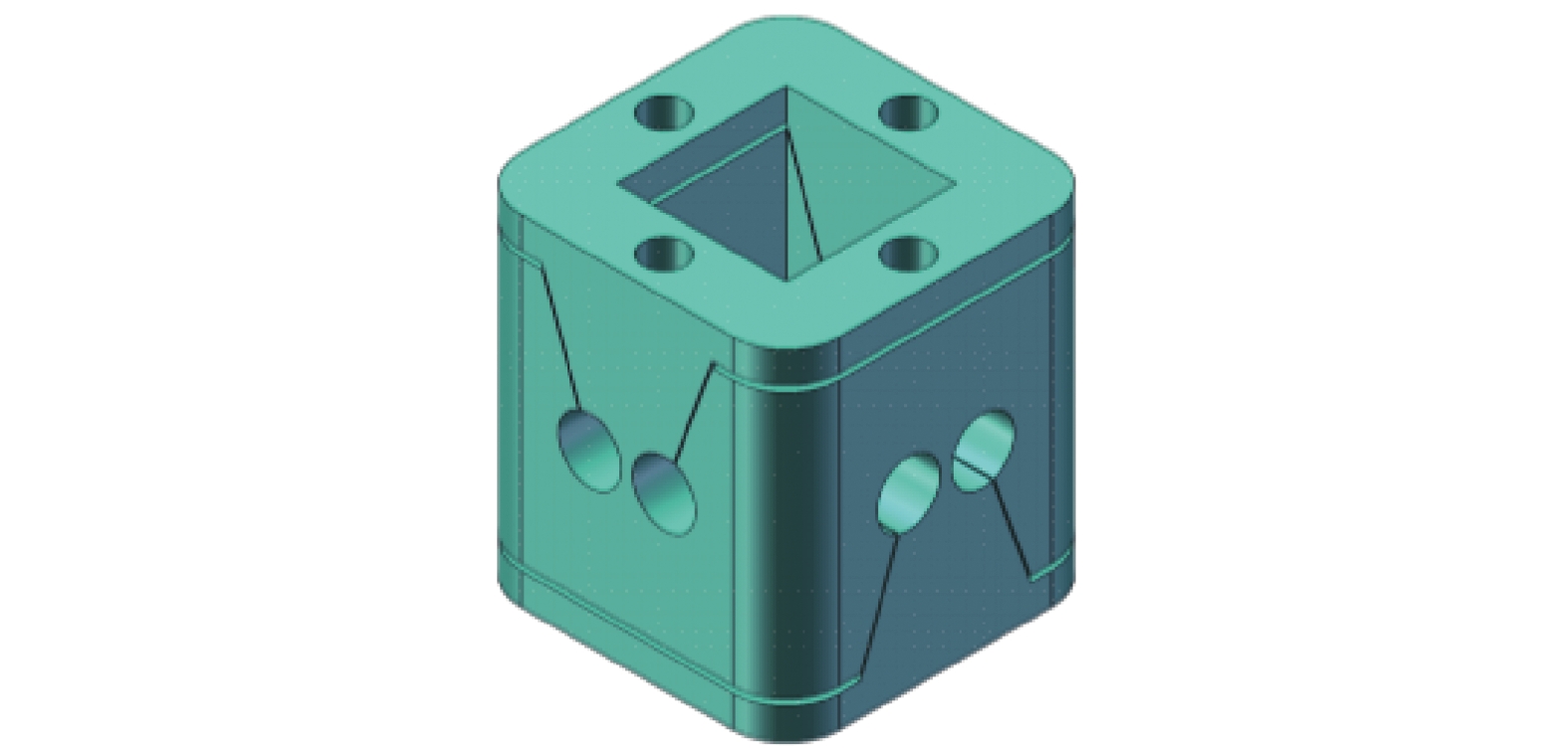
根据激光传输系统光束指向要求给出快速反射镜的设计指标如表1所示。设计的两轴柔性支承快速反射镜如图1所示。音圈电机的定子均匀分布并固定在基座上,动子线圈与镜框采用螺钉固连在一起;传感器采用了非接触式的光栅测微仪;反射镜采用胶结方式与镜框固连;柔性支承的下连接块固定在基座中间,上连接块与镜框固连,上下连接块之间通过四个柔性铰链连接在一起,依靠柔性铰链的弹性变形实现反射镜角运动以及对反射镜运动的约束。
Index Parameter Size Φ100 mm×7 mm Angle range ±10 mrad Closed-loop bandwidth 200 Hz Positioning accuracy 5 μrad Table 1. Design index of fast steering mirror

Figure 1. Structure component of fast steering mirror
根据各零件个运动情况,将整个系统分为固定部分和摆动部分。摆动部分包括反射镜、镜框、音圈电机的动子和柔性支承。系统的转动惯量主要受反射镜、镜框和动子线圈的几何形状、安装位置和材料的影响。系统摆动部分的材料属性如表2所示。
Parts Name of material Density/
kg∙mm−3Young's modulus/GPa Poisson
rateMirror Aluminium alloy 2.7e−6 71 0.33 Flexible support Titanium alloy 4.48e−6 110 0.34 Coil stator Copper 8.9e−6 8.9e−6 0.37 Mirror frame Aluminium alloy 2.68e−6 69 0.33 Table 2. Material properties of swing parts
根据反射镜、镜框和线圈动子的结构、位置和材料属性,可以得到系统运动方向上的转动惯量J1。表3列举了利用SOLIDWORKS分析得到的快速反射镜运动方向上的质量和转动惯量。
Total mass/kg Moment of inertia of x axis/kg∙mm−2 Moment of inertia of y axis/kg∙mm−2 0.388 489.091 489.091 Table 3. Mass properties of swing part of fast steering mirror
为了避免谐振问题,在设计系统时应保证系统的各阶固有频率都应该远高于系统的闭环带宽,按照这种思路,就要求运动方向上的固有频率要非常高,也意味着运动方向上的刚度要非常大,但又因为柔性支承需要提供系统的运动方向的自由度,这又要求运动方向上的刚度非常小。为了解决这种冲突,允许柔性结构的刚度在允许范围内尽量取小,使系统在运动方向上的固有频率也尽可能小于闭环带宽,然后采用控制系统的作用来抑制运动方向上谐振。采用这种方法时,运动方向上的一阶谐振频率f1应满足如下公式:
式中:fc为系统期望的闭环带宽。为了简化分析,将快速反射镜系统看成简单的质量刚度系统[8],则质量刚度之间应满足如下关系:
式中:K,J,f分别为研究对象的刚度、转动惯量和谐振频率。在持续推力作用下,音圈电机所需提供的驱动峰值力矩应满足如下关系:
式中:Fp为音圈电机可以提供的峰值推力;Kθ为系统运动方向上的转动刚度;θmax为系统期望的最大转角范围;J1为运动方向上转动惯量。反射镜的运动范围较小,有
式中:l为音圈电机的驱动轴到转动中心轴的距离;smax为反射镜的最大运动行程;S为音圈电机的总行程。为了满足以上要求,综合考虑设计成本,选取的音圈电机的参数如表4所示。
Performance parameter Symbol Value Unit Direct current resistance R 3.7 Ω Inductance L 1.0 mH Back potential constant ke 3.5 V/m·s−1 Force constant kf 8.9 N/A Sustained thrust Fc 16.3 N Peak thrust Fp 44 N Total travel S ±2 mm Coil side clearance Cl 0.4 mm Coil assembly weight mc 45 g Magnetic steel component weight mf 225 g Table 4. Performance parameters of voice coil motor
从机械原理角度来看,由柔性结构提供支承的快速反射镜是一个过约束的系统,系统依靠柔性支承的作用支承反射镜及镜框,通过柔性支承的弹性变形提供运动方向上的自由度并限制其他方向的自由度,因此要求柔性支承在运动方向上具有较小的刚度,而在非运动方向上则需要具有较高的刚度。根据以上要求设计的快速反射镜系统的柔性支承结构如图2所示。该柔性支承由4个尺寸完全相同的直圆柔性铰链单元进行拓扑组合构成,可以为系统提供绕两轴进行转动而限制其他方向自由度的约束,同时还可以起到支承反射镜和镜框的作用。在运动方向上柔性支承结构可以简化为2个柔性铰链间的并联,根据刚度串并联关系,系统的在运动方向上的转动刚度为:

Figure 2. Structure of flexible support
式中:K为单个柔性铰链的刚度。如果可以得到单个柔性铰链的转动刚度,即可得到系统在运动方向的转动刚度。下面对单个柔性铰链的刚度进行分析。
直圆柔性铰链可以通过线切割法,沿着矩形截面梁的宽度,切除两块对称的由半直圆围城的封闭区域内的材料得到,其结构如图3所示。

Figure 3. Structure and force diagram of flexible hinge
根据卡氏第二定理[9],矩形截面梁在受到扭矩作用时自由端的角变形与其扭转刚度间存在如下关系:
式中:αz为矩形截面梁自由端在扭矩Mz的作用下产生的角变形,该角度也等于矩形截面梁绕曲线方程的一阶微分,为:
将柔性铰链在槽口
$ - \dfrac{{\text{π}}}{2} \le \alpha \le \dfrac{{\text{π}}}{2}$ 范围内分成无限小的N个微元进行受力分析,每个微元都可以近似看成是一个截面高度为h的矩形截面梁,h=t+2R−2Rcosδ,根据材料力学的知识,微元中性面在x方向上的曲率为:式中:E为材料的弹性模量;Iz为矩形微元截面梁在z向的惯性矩:
式中:b为柔性铰链的宽度。图3中还存在着隐藏的几何关系x=Rcosδ。联立求解公式(6)~(9),可以得到柔性铰链的转动刚度为:
式中
$ s={}^{R}\!\!\diagup\!\!{}_{t}\;$ 。设计的柔性铰链的尺寸如表5所示,此时柔性支承结构的转动刚度为52 Nm/rad。
Structure name Symbol Value Unit Cutting radius R 3 mm Thickness t 1 mm Width b 7 mm Table 5. Structure parameters of flexible hinge
-
两轴柔性支承快速反射镜系统驱动和负载在单个运动轴上的作用形式可以用图4表示。运动轴上两个音圈电机在输入电压和反电动势的共同作用下产生对负载的推拉效果,推力和拉力的方向相反、大小相等,力的大小与线圈电流成正比,比例系数为kf,两者共同作用在镜框上驱动反射镜产生角位移,负载运动速度反过来也会影响音圈电机回路的电势,反电势的大小与负载运动速度成正比,比例系数为ke。
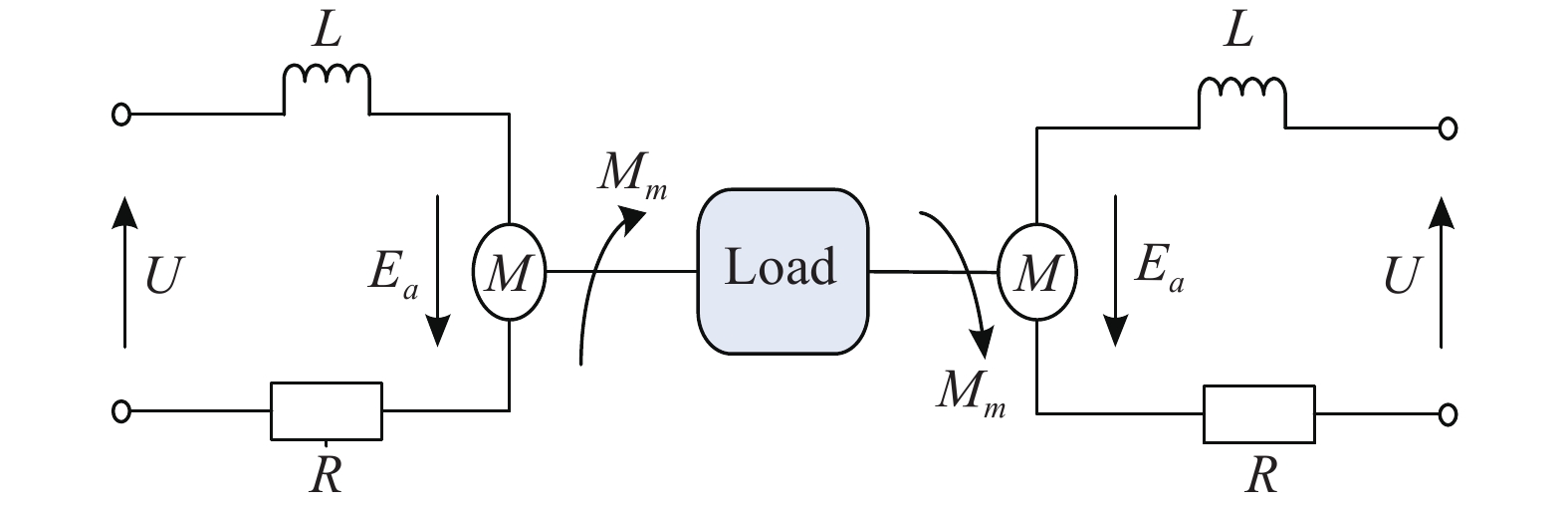
Figure 4. Voice coil motor driving and load model
系统的开环数学模型用控制框图表示如图5所示,图中,G1(s)是音圈电机传递函数,G2(s)是线圈电流到输出力的传递函数,G3(s)是作用在镜框上的力对摆动部分产生的力矩传递函数,G4(s)是系统摆动部分传递函数,H(s)是负载对电机反作用的传递函数,其值分别为:

Figure 5. Open loop control diagram of fast steering mirror
根据控制框图计算得到快速反射镜系统的开环传递函数为:
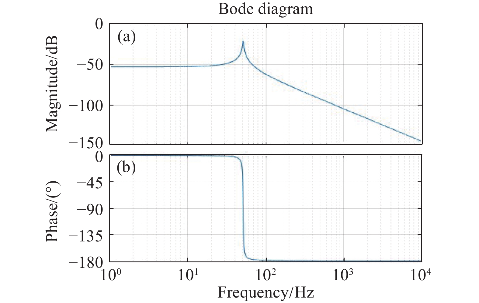
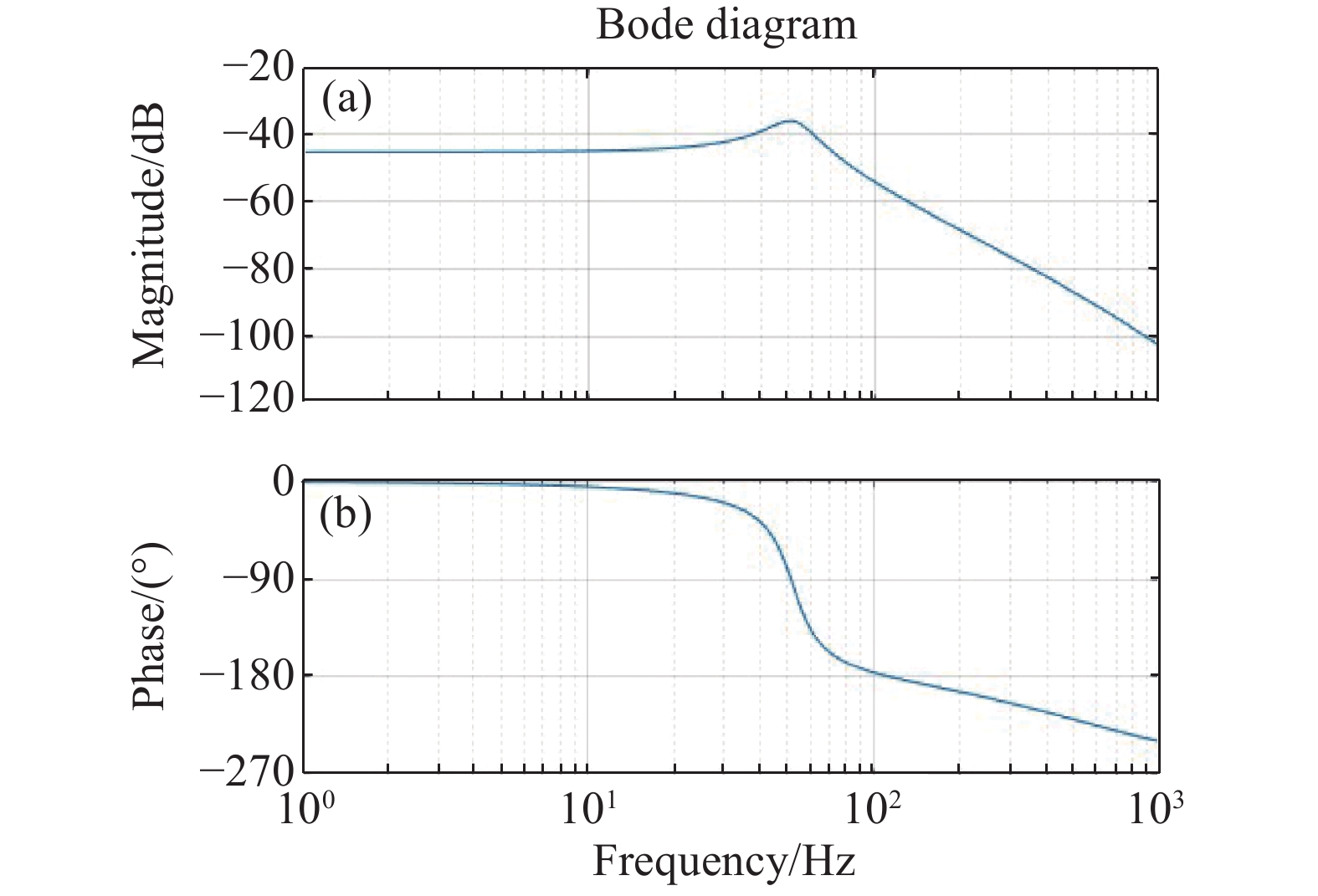
带入具体参数得到音圈电机输出力到快速反射镜位置转角和系统开环传递函数的对数频率特性曲线分别如图6和图7所示。从图6中可以看到快速反射镜的机械部分在频率为52 Hz时存在一个明显的谐振峰,峰值为-22.4 dB。对比图6和图7可以看出:音圈电机作用后系统的开环系统谐振峰仍出现在52 Hz处,但是谐振峰值变得平缓,这是由于音圈电机的作用相当于在系统中引入了一个一阶惯性环节,该环节不会改变谐振峰的作用位置,而是相当于引入了一个低通滤波器,对谐振峰进行了部分抑制。

Figure 6. Frequency response characteristics of the output force of voice coil motor to the position of mirror

Figure 7. Open-loop frequency response characteristics
将快速反射镜的开环传递函数写成尾一标准型,则:
为了完全抑制系统运动方向上的谐振,系统控制器的传递函数应该为:
式中:k为控制器增益;Tf为滤波时间常数。取控制系统开环截止频率为ωo,有:
求解上式可以得到:
取Tf=0.000 4 s,ωo=750 rad/s,控制器为:
加入控制器作用后,快速反射镜位置闭环系统的频率响应特性如图8所示。从图中可以看到运动方向上的谐振峰被抑制,系统的闭环带宽为203 Hz,符合设计要求。快速反射镜的闭环阶跃响应如图9所示。从图中可以得到,闭环系统的调节时间为5 ms,超调量为6.5%。
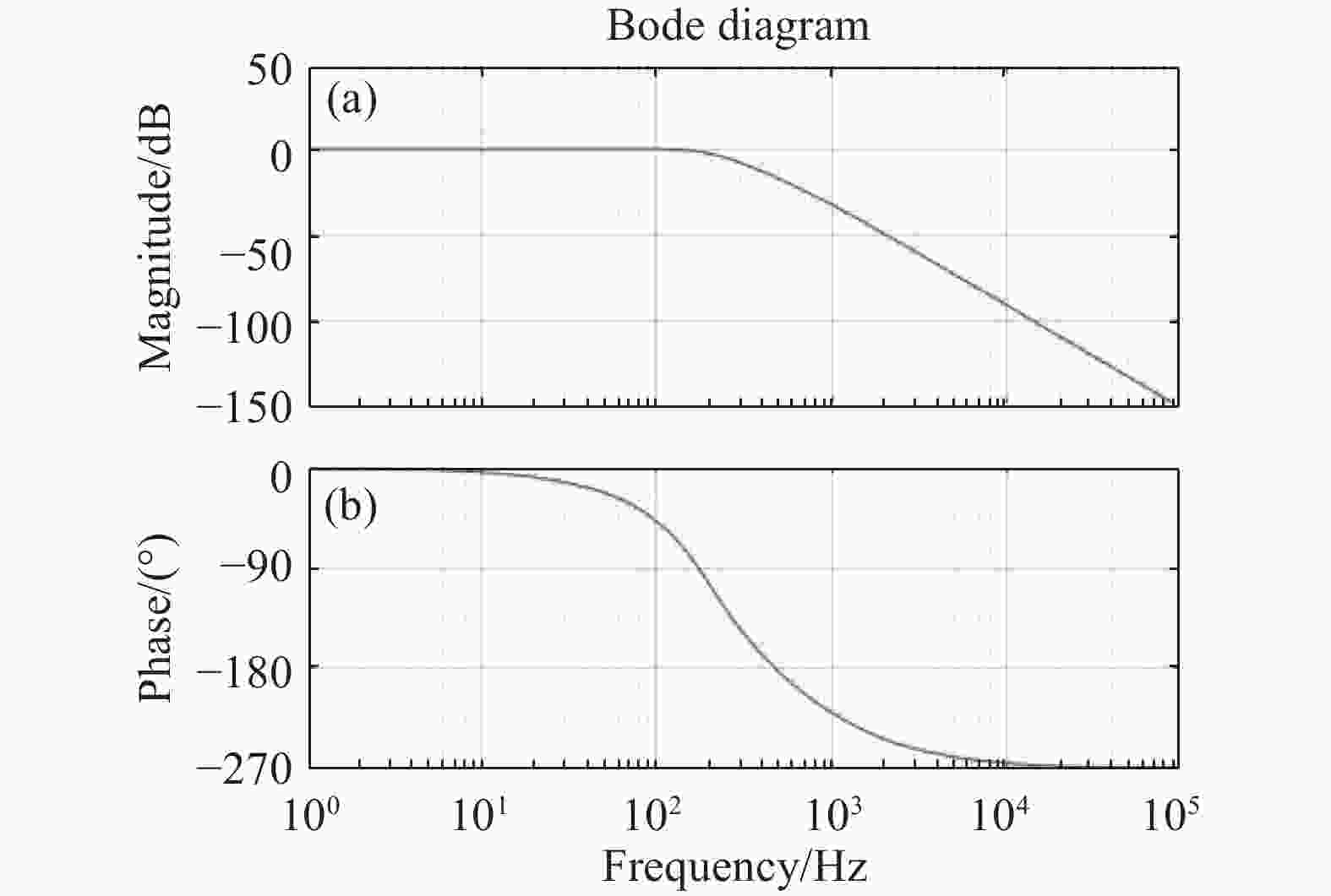
Figure 8. Frequency response characteristics of closed loop control system
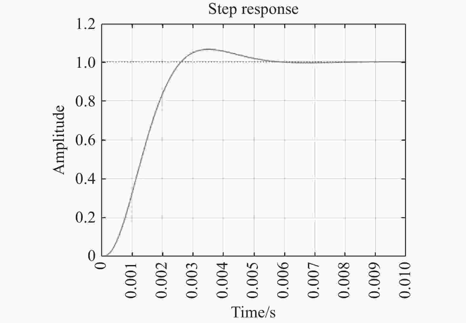
Figure 9. Step response of closed loop control system
-
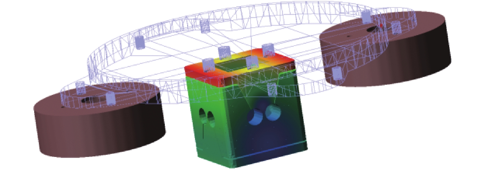
为了测试柔性支承结构的参数选择是否合理,利用SIMULATION软件对快速反射镜的摆动部分进行了频率分析。分析时对支承结构的螺孔进行固定,镜框与反射镜、柔性支承和4个线圈动子均采用接合的方式连结模拟实际装配,机构的有限元模型以及振型图如图10所示。从图中可以看到,快速反射镜一阶、二阶谐振频率亦即系统在运动方向上的谐振频率约为52 Hz,与理论计算结果相同。系统的三阶谐振频率为223.63 Hz,处于系统的工作带宽之外,符合设计要求。
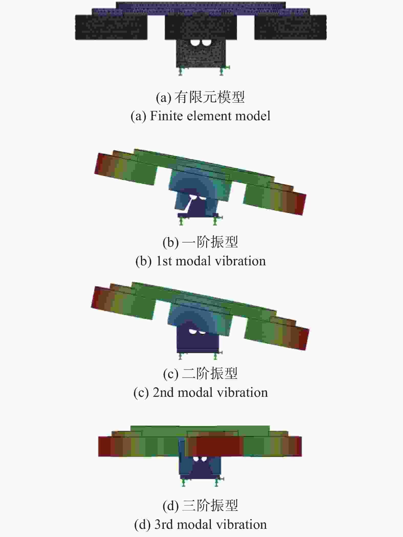
Figure 10. Finite element analysis result of swing part
考虑到两轴系统的对称性较好,在进行动力学研究时只选取其中一个运动轴作为研究对象。将SOLIDWORKS中建立的摆动组件的三维模型导入多体动力学软件ADAMS,导入后的模型的模型是刚体模型,需要先将柔性支承的刚性模型生成柔性体模型。将刚性体模型转化成为柔性体模型有两种方法,一种是借助有限元软件生成模态中性文件,然后将模态中性文件导入到ADAMS中,另外一种是直接使用ADMAS的FLEXVIEW插件直接生成柔性体文件,这里选的是第二种方法。生成柔性体文件后,需要再次确认个构件之间的约束是否正确。为了获取系统在运动方向上的频率响应函数,需要使用到ADAMS中的振动仿真分析模块Vibration,振动分析结果如图11所示。
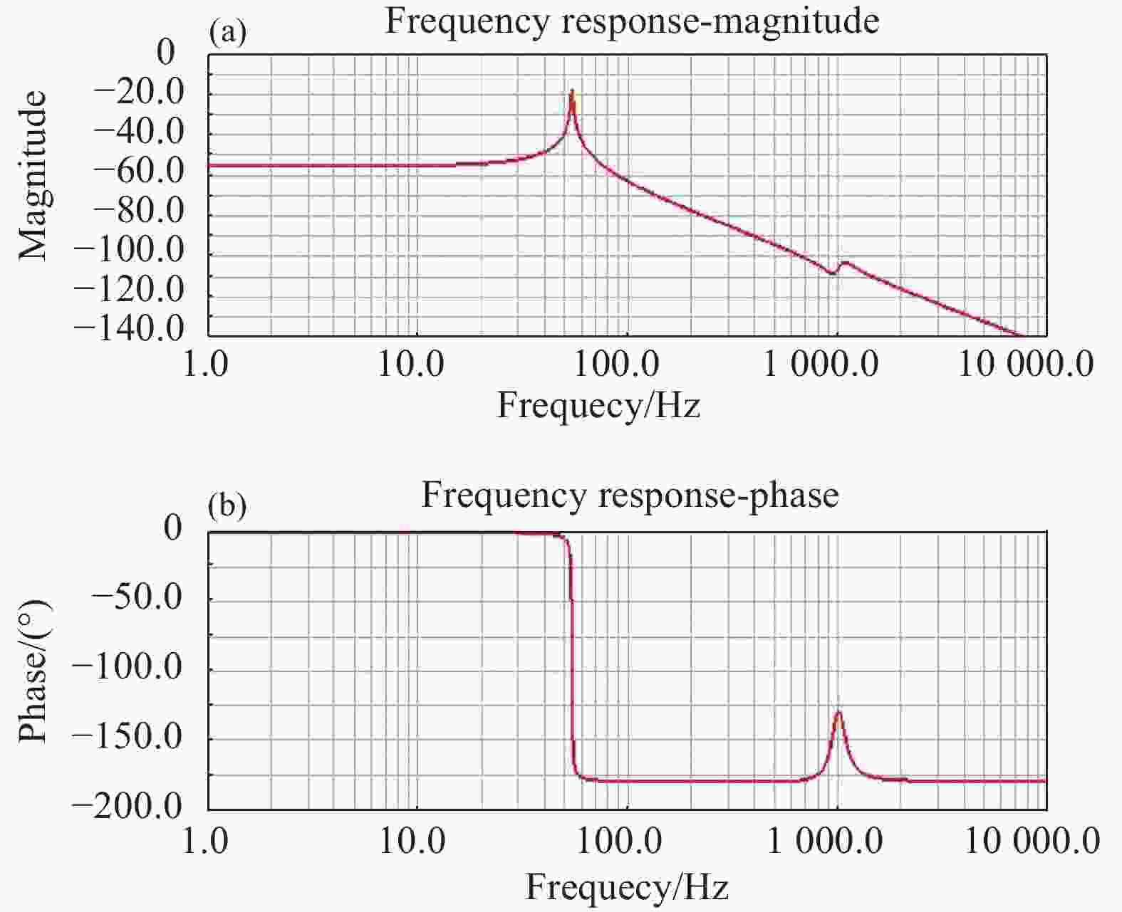
Figure 11. Frequency response characteristic of motion axis
从图11可以看到,运动方向上的一阶谐振频率为54 Hz,与理论计算结果和有限元仿真结果的误差为3.8%。谐振峰值为−18.8 dB,与理论计算结果的误差为16.1%。仿真结果还显示运动方向存着理论分析未曾考虑的高频谐振频率。
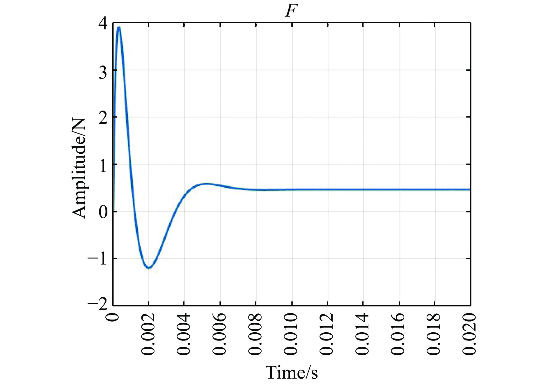
为了测试反射镜输出的渐进跟踪能力和系统时域性能指标,联合ADAMS和MATLAB进行了仿真测试[10]。通过ADAMS的CONTROL插件生成系统摆动部分的非线性模型,模型的输入和输出分别是音圈电机输出力信号和反射镜的转角信号,再在SIMULINK中完成系统控制器和控制信号到音圈电机输出力信号等环节的搭建,实现控制系统对运动系统的控制。系统输入信号为幅值0.001的阶跃信号时,力信号曲线如图12所示,从图中可以看到,系统稳定时,控制力信号的值为0.5 N。联合仿真过程中系统的运动学模型如图13所示,反射镜输出转角信号如图14所示。从图14中可以看到,反射镜的转角位置可以实现对阶跃信号的渐进跟踪,系统的超调量为3.5%,调节时间为10 ms,与理论计算结果相比,实际系统的超调量有所降低,调节时间有所增加,偏差分别为3%和5 ms。
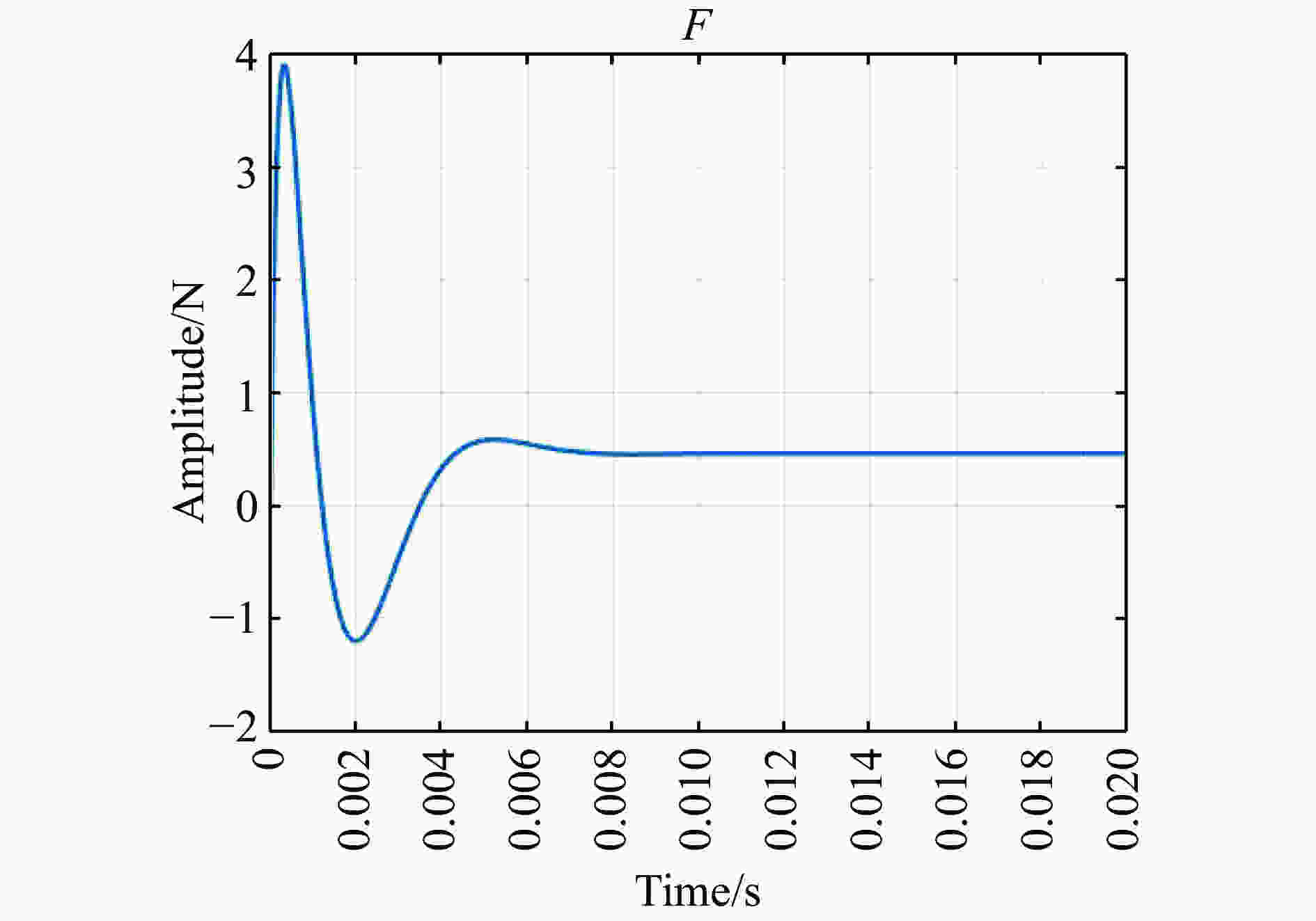
Figure 12. Control signal

Figure 13. Kinematics model of swing parts

Figure 14. Output angle signal of mirror
-
文中根据激光系统光束指向要求给出的快速反射镜的设计指标,设计了一种两轴柔性支承快速反射镜,完成了从结构到控制的一体化设计,实现了在虚拟样机结果设计阶段快速反射镜控制系统的性能预测和确认。研究内容主要包括结构设计、控制系统设计和联合仿真测试三个部分。在结构设计阶段,完成了音圈电机、传感器的选型,确定了反射镜、镜框、基座等零件的几何尺寸、材料等,着重研究了以柔性铰链为基本单元拓扑得到的柔性支承的结构形式和频率特性,通过利用卡氏第二定理和材料力学知识,确定了柔性铰链的刚度计算公式,进而得到柔性支承结构的刚度;在控制系统设计阶段,先是根据快速反射镜各组件间的关系建立控制系统的数学模型,然后带入结构设计阶段确定的结构参数和音圈电机的电气参数,进而得到快速反射镜运动部分的传递函数以及系统开环传递函数。为了抑制开环频率响应特性的谐振,设计了位置闭环控制器,闭环控制系统闭环带宽达到了203 Hz,调节时间为5 ms,超调量为6.5%;最后使用了有限元软件、多体动力学软件和MATLAB进行了联合测试研究。采用有限元软件进行频率特性仿真结果显示系统的运动方向的谐振频率为52 Hz,与理论计算结果相同。ADAMS中振动分析的结果显示运动方向的谐振频率为54 Hz,与理论计算结果和有限元仿真结果的误差为3.8%。联合MATLAB控制信号输出得到摆动部分的运动学仿真结果显示,快速反射镜控制系统可成功实现对阶跃输入的渐进跟踪,时域输出结果显示,系统的超调量为3.5%,调节时间为10 ms,与理论计算相比,实际系统的超调量有所降低,调节时间有所增加,偏差分别为3%和5 ms。下一步工作的重点是完成试验样机的试制,并在此基础上完成快速反射镜控制系统实验平台的搭建和反射镜输出实验数据的获取和分析,进一步验证在虚拟样机设计阶段结构和控制系统联合仿真测试预测和确认的性能指标的准确度。
Integrative design of structure control for two-axis fast steering mirror with flexible support
doi: 10.3788/IRLA20190479
- Received Date: 2020-04-07
- Rev Recd Date: 2020-05-09
- Available Online: 2020-07-23
- Publish Date: 2020-07-23
-
Key words:
- fast steering mirror /
- structure design /
- flexible support /
- control system
Abstract: To predict and confirm the frequency characteristics and time-domain performance of the fast steering system (FSM) in the structural design stage, a two-axis flexible-supported FSM was studied and tested. A new flexible support structure was proposed, and the main structural parameters of the FSM system were designed based on the performance index of FSM which is decided by the beam requirement of laser transmission system. The dynamic mathematical model of the system was studied, and the control mode and parameters of the closed-loop system were determined. The rigid-flexible coupling model of the swing part of the system was established, and the structural non-linear model was obtained. The joint simulation test of the system and the motion system were carried out based on the model above. The simulation results show that the resonance frequency of the system in the direction of motion is 54 Hz, and the errors between the calculated result and the finite element result is both 3.8%, and position closed loop bandwidth is 203 Hz which is right to the index. The output results in time domain show that the overshoot of the system is 3.5% and the adjustment time is 10 ms, the deviations from the theoretical results are 3% and 5 ms.


 DownLoad: