


-
基于面阵探测器的扫描型红外成像技术主要应用于红外搜索跟踪一体化系统中,使系统同时具备周扫搜索以及凝视跟踪功能。采用面阵探测器的红外成像系统在以1 s/圈的速率进行扫描时,由于成像需要一定的积分时间,会导致焦平面和景物之间产生相对运动,造成拖尾,使图像变得模糊。因此需要通过扫描镜回摆补偿技术,补偿平台扫描带来的物面移动,使图像稳定,不产生拖影。
国内外均开展了基于面阵探测器的扫描型红外搜索跟踪系统的相关应用研究。在2014 年的法国巴黎海军装备展上,HGH 红外系统公司推出的高分率广域监视系统-Spynel-X8000。该系统采用反扫补偿型像移补偿方案,采用制冷型中波红外面阵探测器,可以2 s/圈的搜索速率完成方位 360 °扫描,俯仰视场 5°。中国科学院上海技术物理研究所于2016年设计了面阵探测器连续扫描成像光学系统,系统焦距73 mm,F/2,搭配320×256的探测器,实现了固定焦距下的凝视跟踪与周扫搜索[1-7]。
红外系统对目标的探测、发现与识别需要不同的空间分辨率。对目标进行探测时,采用大视场搜索发现;探测到疑似目标时,采用长焦距进行识别。因此,红外搜索跟踪系统需要两档焦距,分别对应目标的搜索与跟踪。目前,对于红外变焦面阵搜索光学系统的设计国内外都尚未见报道。
红外两档变焦面阵扫描光学系统要解决的技术难点是:一是解决两种焦距状态下,消除振镜回摆带来的像差,保证扫描过程中成像清晰;二是解决两种焦距状态下,减小振镜回摆带来的畸变,保证图像在回摆过程中,全视场范围内的配准,使图像保持稳定。文中创新地提出了红外两档变焦面阵扫描光学系统的结构型式。提供了一种红外两档变焦面阵扫描光学系统,通过一组光学元件的移动,可实现两档变焦面阵扫描、两档凝视跟踪、−30 ℃~+60 ℃工作温度补偿、不同距离成像的调焦。
-
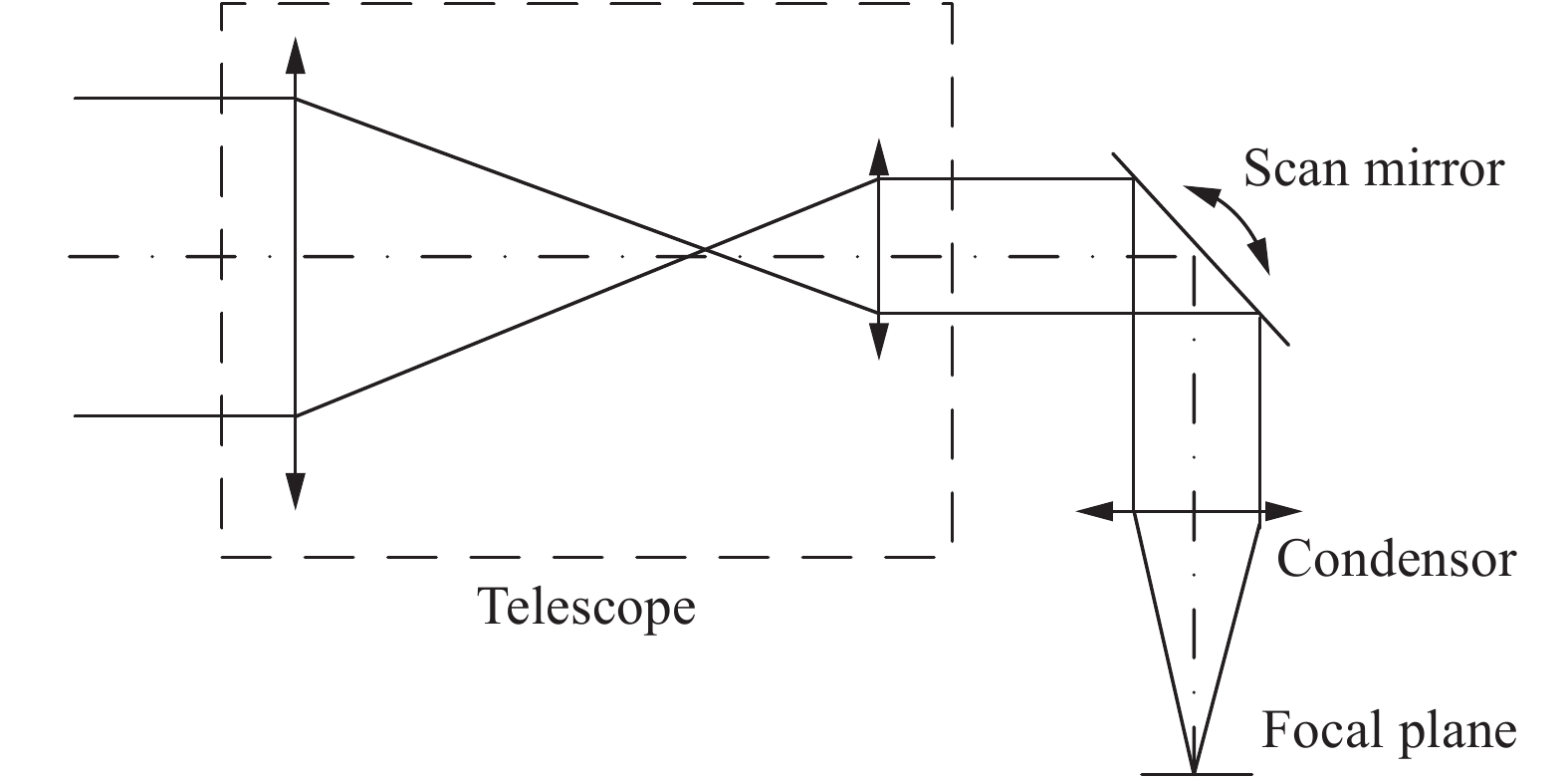
扫描光学系统主要作用是扩大光电系统的扫描方向的视场,常见的光学扫描方式有:物方扫描、像方扫描、中间平行光路扫描,中间会聚光路扫描等结构型式等。中间平行光路扫描光学系统如图1所示,通过在前置望远组件和后置会聚组件中间的平行光路中,引入扫描反射镜,实现扫描。该方式扫描反射镜尺寸较小,且在一定范围内,可保证良好的成像质量,可以应用于红外搜索跟踪一体化光学系统中。

Figure 1. Middle optical path parallel scanning layout
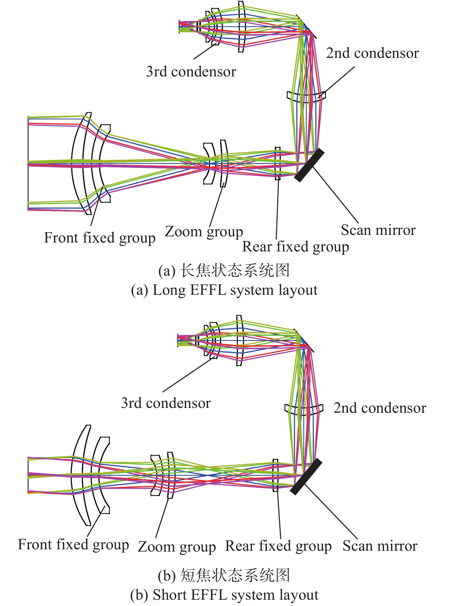
通过结合中间光路扫描、三次成像、两档变焦的结构形式,创新地提出了一种三次成像红外两档变焦中间光路扫描型光学系统,其组成如图2所示。

Figure 2. Three-times imaging scanning zoom optical system structure
为了获得更好的性能,系统采用制冷型红外探测器,光学系统光阑与探测器冷光阑100%匹配。同时为了减小光学系统的体积,减小第一片透镜的口径,需要将入瞳设计到第一片透镜的前端面上。为了进一步减小振镜的尺寸,望远系统的出瞳需要设计到振镜位置。
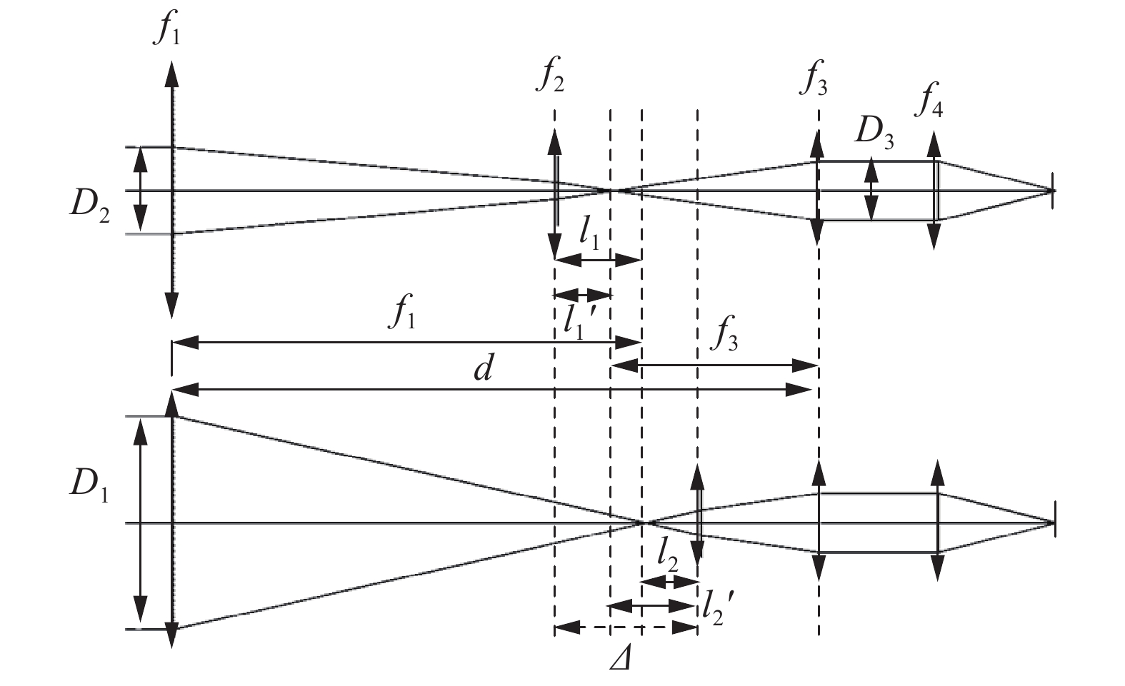
其中,二次会聚组、三次成像组主要作用是实现入瞳、望远镜出瞳、冷光阑的匹配。变焦系统的功能主要由前置望远镜完成,为简化系统,将振镜、二次会聚组、转折镜、三次成像组等效为一正透镜组,如图3所示。

Figure 3. Two EFFL telescope layout
如图3所示,前固定组焦距为f1,变焦组焦距为f2,后固定组焦距为f3。前固定组与后固定组之间距离为d,变焦组移动量为Δ。D1为长焦系统口径,D2为短焦系统口径,D3为后固定组口径。因振镜与光轴程45°放置,因此,振镜有效口径为椭圆形状,D3为振镜短轴口径,其长轴口径为
$ \sqrt{2}{D}_{3} $ 。光学系统需要实现两档变焦,采用单变焦组实现,其两个位置正好处于物像交换原则的两个位置。因此有:
由图3可知,存在以下关系:
变焦组移动距离如下:
将公式(3)代入,有:
两档变焦倍率为Γ,短焦状态时,变焦组放大倍率为β1,长焦状态变焦组放大倍率为β2,则有:
根据高斯光学公式有:
通过上述公式,可以求解出物距与像距。则变焦组的焦距为:
同时,根据F数匹配的原则,有:
针对后会聚透镜组f4,透镜组口径为D3。红外探测器的F数为F/#,则:
上述过程,即为单变焦组移动两档变焦望远系统设计的高斯光学求解过程。实际设计过程中,首先通过高斯光学求解出各组元的焦距、间隔,然后再进行单透镜、双透镜的替换,经过光线追迹优化,完成最终系统的设计[8-10]。
-
根据上述理论模型,以一两档变焦面阵扫描红外光学系统的具体设计为例进行设计。为满足应用需求,要求光学系统具备73 mm、180 mm两档面阵扫描的功能。选用红外探测器工作波段3.7~4.8 μm,像元阵列数为640×512,像元大小为15 μm,探测器F数为F/2;光学系统不同焦距的视场如表1所示。
EFFL/mm Aperture/mm FOV/(°) IFOV/mard 73 36.5 7.5×6.0 0.25 180 90 3.1×2.4 0.083 Table 1. Optical system specifications requirement
根据两档变倍光学系统的高斯光学求解过程,令前固定组焦距为f1=200 mm,后固定组口径D3=25 mm,则后固定组f3=87.22 mm,后会聚透镜组f4=50 mm。下面给定不同的前固定组与后固定组之间距离为d,根据公式计算变焦望远镜各组元高斯参数如表2所示。
由表2可见,在两档变焦望远系统中,系统总长增加时,则变焦组移动距离减小。进行光学系统初始结构设计时,需要在系统总长,与变焦组移动距离之间平衡。为减小变焦距离,缩短变焦时间,以前固定组与后固定组之间距离为d=275 mm为初始结构输入,经过优化设计,光学设计结果如图4所示。系统采用折衍混合的透射式三次成像的结构形式,具有100%冷光栏效率。光路由5组9片透镜组成。前固定组为1片硅透镜、1片锗透镜组成。变焦组由1片氟化钡透镜、1片锗透镜组成。后固定组为正光焦度非球面衍射AMTIR1透镜,其前表面是非球面衍射面。光学系统体积包络尺寸为300 mm×200 mm×100 mm。
Number Distance between front group and real fix group d/mm Zoom group EFFL f2/mm Zoom group movement Δ/mm 1 260 131.54 122.77 2 265 107.38 100.22 3 270 83.22 77.70 4 275 59.05 55.15 5 280 34.88 32.56 Table 2. Different initial Gauss optical parameters

Figure 4. Optical system design result
变焦系统采用两档光学变焦的结构形式,通过单个变焦组的移动,实现73 mm、180 mm两档焦距。下面给出了两档焦距下的的调制传递函数MTF图。由图5可知,光学系统在两档焦距状态下,MTF均大于0.4。

Figure 5. Optical system MTF
-
红外光学系统冷反射指制冷型探测器“看到”自身的反射像,它严重影响红外系统的图像质量。目前一般采用YNI参数来评估系统冷反射情况[11-12]。焦距73 mm、180 mm时,系统YNI计算如表3所示。
根据分析知,长焦时透镜3,透镜4的YNI较大,其主要原因是两个变焦透镜基本位于中间像面,其边缘光线高度较小造成。通过对冷反射路径进行光线追迹,可知冷反射现象较小。
Number Surface EFFL 73 mm YNI EFFL 180 mm YNI Lens 1 2 4.22 25.63 3 −1.96 −11.90 Lens 2 4 −0.73 −4.46 5 1.81 11.02 Lens 3 6 −1.85 0.02 7 −0.85 0.23 Lens 4 8 −0.38 0.55 9 −1.19 0.33 Lens 5 10 2.18 2.17 11 −0.50 −0.51 Lens 6 15 2.53 2.50 16 −0.14 −0.15 Lens 7 20 3.95 3.97 21 −0.21 −0.22 Lens 8 22 3.15 3.16 23 5.74 5.75 Lens 9 24 6.24 6.26 25 1.82 1.82 Table 3. Optical system YNI analysis data
-
振镜位于中间平行光路中。具有两种工作状态:锁紧状态与回摆补偿状态;振镜处于锁紧状态时,与望远镜光轴程45°放置,将光路转折90°。光学系统应用于凝视跟踪模式,可进行两倍变焦。振镜处于回摆补偿状态时,光学系统工作于周扫搜索模式,通过振镜往返扫描来补偿平台扫描转动带来的曝光时间内的物面的移动,保持图像清晰。
振镜短轴尺寸为25 mm,长轴尺寸为35.35 mm;考虑到振镜需要高频振动,要求具有足够的强度和较小的重量,因此选用碳化硅材料制作。
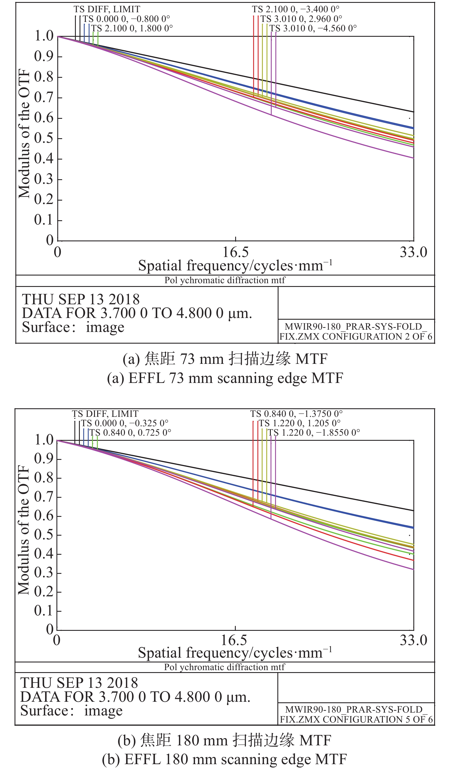
红外系统的焦距为73 mm时,面阵周扫的频率分别为1 s/圈;红外系统焦距为180 mm时,面阵周扫的频率为2.47 s/圈。在固定振镜摆角范围的情况下,积分时间可选取为4.0 ms;此时振镜补偿角度为振镜的摆动角度为±0.58°。短焦状态在振镜处于边缘角度下MTF如图6(a)所示;长焦状态在振镜处于边缘角度下MTF如图6(b)所示。
振镜的目的是使得在红外面阵探测器的成像积分时间内探测器所凝视的视场保持不变。因此需要实现平台周扫、振镜回扫、探测器积分三者之间的同步与参数匹配。振镜速度与探测器积分时序图如图7所示。

Figure 6. Scanning edge MTF

Figure 7. Relation of scan mirror velocity and detector integration
-
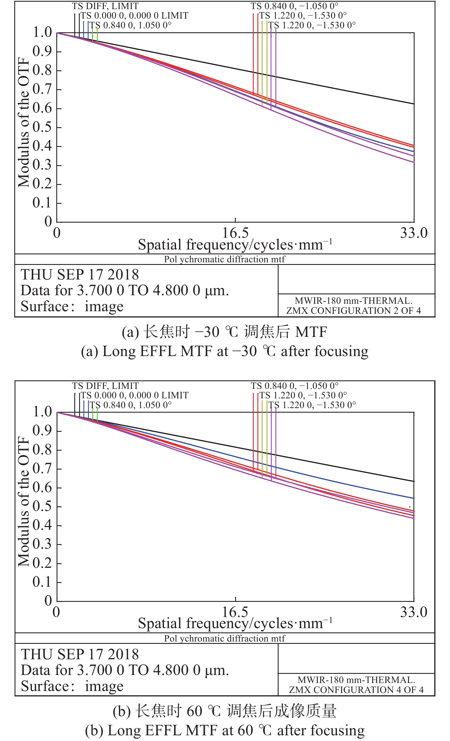
红外光学材料的折射率受温度影响变化较大,由于没有采用光学被动消热差的设计,因此,如果不进行调焦,是无法进行清晰成像的。在利用变焦组进行调焦后,通过仿真分析,−30 ℃时长焦状态下成像质量如图8(a)所示,MTF在33 Lp/mm时,全视场大于0.3。此时焦距为180. 7 mm,补偿组后移2.3 mm。在工作温度60 ℃时,成像质量如图8(b)所示,此时焦距为177.0 mm,补偿组前移1.90 mm。

Figure 8. MTF after focusing
-
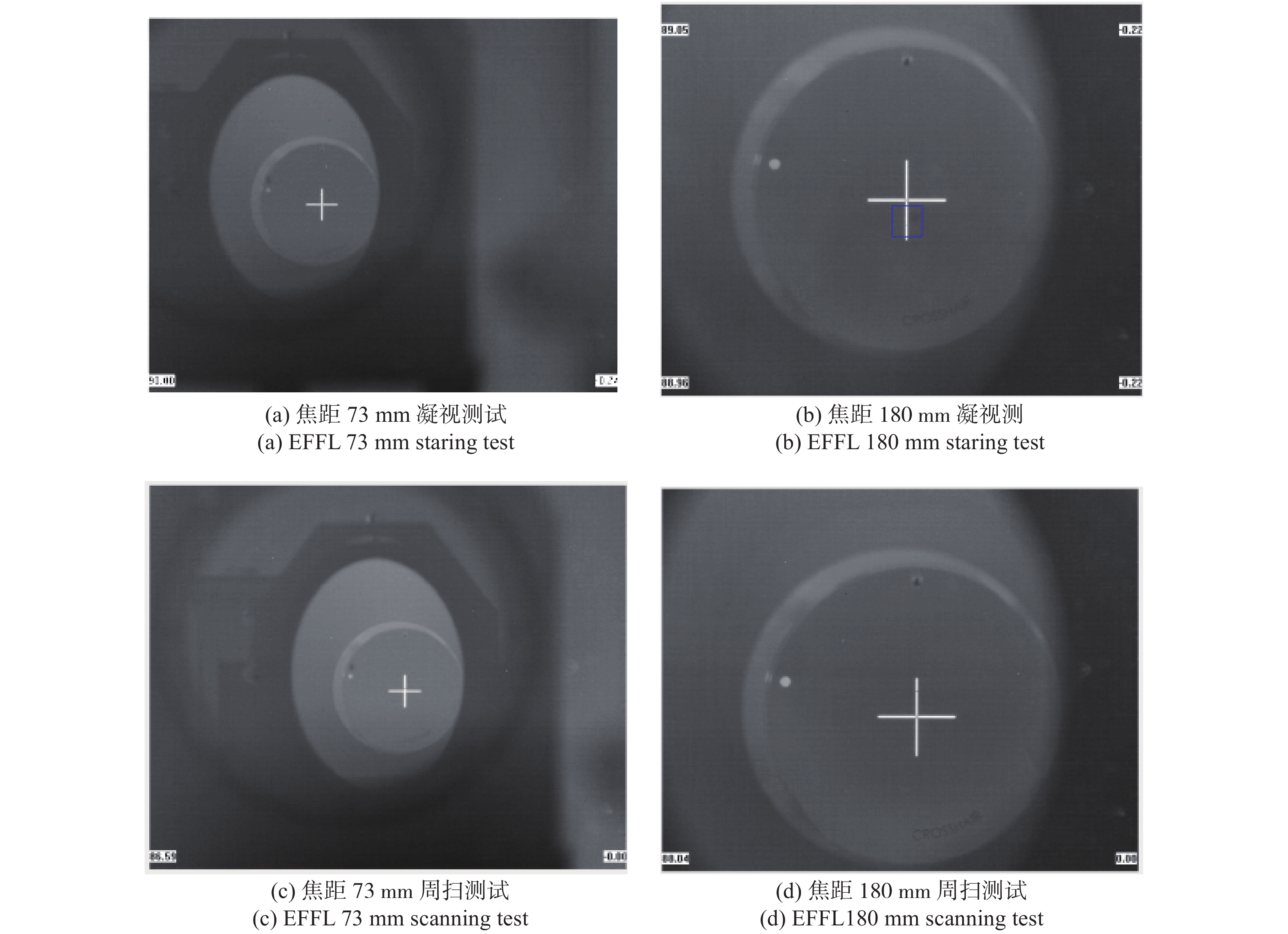
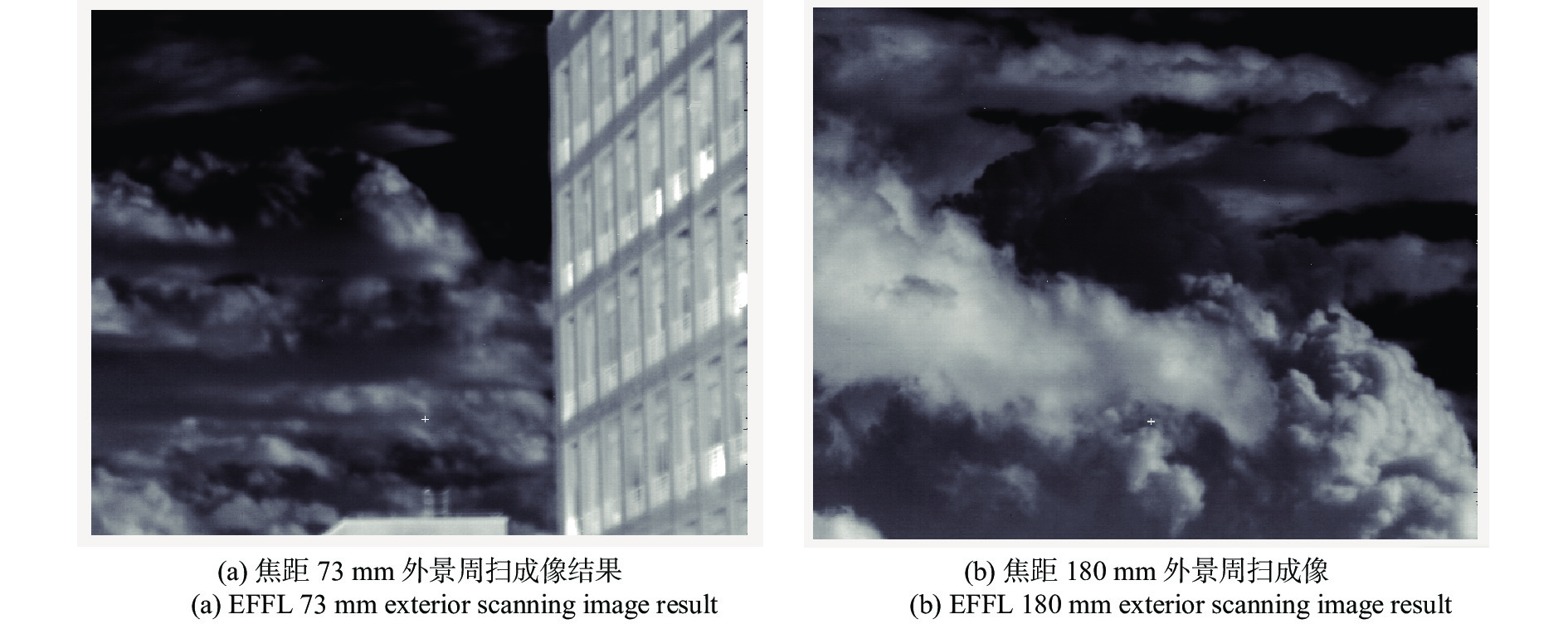
提出了两档变焦中间光路扫描红外光学系统的结构型式,推导了各组元高斯光学参数,设计了两档变焦面阵扫描光学系统,并进行了分析。将研制完成的变焦系统进行了实验室和外场测试,光学系统在凝视状态与快速周扫状态下,均能获取良好的面阵图像。该系统结构型式简洁紧凑,可广泛应用于红外搜索与跟踪一体化系统中。
Optical design of two-stage zoom scanning infrared system with array detector
doi: 10.3788/IRLA20200007
- Received Date: 2019-12-20
- Rev Recd Date: 2020-01-14
- Available Online: 2020-05-26
- Publish Date: 2020-08-28
-
Key words:
- infrared search and tracking /
- array detector scanning /
- triple imaging /
- infrared zoom
Abstract: A two-stage zoom array detector scanning infrared optical system was proposed. On the basis of traditional infrared secondary imaging optics, a two-stage zoom front telescope system was added to realize two-stage zoom by moving the zoom group along the optical axis. The zoom group adjusted the distance along the optical axis, and realized the compensation of different working temperature and different object distances. In the middle parallel light path, a galvanometer was introduced, and the galvanometer was used to scan back in the corresponding angle range at a specific frequency, which could compensate for the object movement during the exposure time caused by the rotation of the scanning platform, and keep the image clear and stable during the rotation scanning without any shadow. The system is very compact, and can be widely used in the infrared searching and tracking system.


 DownLoad: