


-
快速三维测量在先进制造、虚拟现实、安全防护等领域变得日益重要,数字光栅投影三维测量技术因其非接触、速度快、成本相对较低等优势,在快速三维测量领域表现了极大潜力[1-4]。传统光栅投影法投影符合正弦分布光栅条纹,通常由频域法或者相移法计算测量所需相位信息。频域法可依据单帧光栅条纹计算相位,但是较难保持待测物体边界、复杂面型等细节信息[5];相移法依据至少三帧以上相移光栅条纹,时域内计算得到相位信息,能较好地保持待测物体细节[6]。
数字投影设备利用数字微镜(Digital Micro-mirror Device,DMD)来投影光栅条纹,数字微镜中可以开和闭的微镜片表征对应像素,单个像素亮度强弱通过调整对应微镜片单位时间内开启时间长短来实现。投影“8”位正弦光栅条纹需要根据条纹灰度变化按照积分时间多次切换数字微镜开闭状态;而投影“1”位二值光栅条纹,数字微镜仅需保持开或闭两种状态,无需进行多次开闭状态切换,能够实现kHz(帧/秒)以上的投影速度。但投影二值光栅条纹不可避免会包含高次谐波,投影设备选择恰当离焦程度,离焦可由高斯低通滤波近似表征,即可滤除投影光栅包含的高次谐波,以生成测量所需正弦光栅条纹图像。基于二值光栅投影快速性,即可实现快速三维测量[7]。
然而,投影设备通常需要较大离焦程度来滤除二值光栅所包含高次谐波,以计算得到精确相位信息。但是,较大离焦程度会减少生成条纹对比度,降低三维测量动态范围;轻微离焦程度能够保证较高的动态测量范围,但是相应高次谐波会引入相位误差,降低三维测量精度。通常有两种思路解决上述问题:(1)优化设计二值光栅,降低所需离焦程度,主要包括:脉宽调制(PWM)和抖动(dithering)、方波等设计方法。其中,PWM [8]和dithering [9]各自适用于较窄和较宽周期二值光栅设计,投影高频方波二值光栅,操作便捷且在不同离焦程度保持良好的一致性。但是,实际测量过程中通常难以精确调整到恰当离焦程度,尤其当所选相移算法步数较低情况下,不可避免会包含高次谐波,降低三维测量精度。(2)通过附加多帧光栅或者进行频域分析进行相位误差补偿。附加多帧光栅条纹,需要投影多帧相移二值光栅,制约了三维测量速度[6];引入频域变换方法,相对难以保持待测物体边界[5]。基于上述,采用较低步数相移算法(例如:快速测量常用三步相移算法),投影设备处在不同离焦程度,均能实现精确相位获取,对快速三维测量具有重要意义。
文中对传统快速三维测量方法做了改进,提出一种基于深度学习精确相位获取的离焦投影三维测量方法。具体而言,在快速测量过程中引入基于深度学习的PDNet(Phase Denoising Network)算法,使用含噪声相位到理想相位的端到端方式来训练PDNet模型,训练完成后使用模型就能够在测量过程中得到精确相位图像。文中将三帧相移二值光栅离焦投影,采用三步相移算法计算得到的包裹相位图像作为输入,对应的理想相位图像通过多步相移算法获得,所提方法能够实现不同离焦下的精确相位获取,进而实现快速精确三维测量。
-
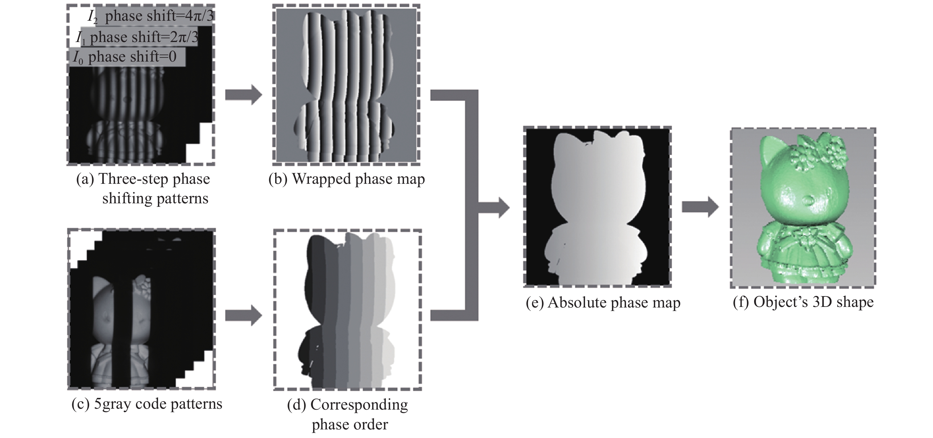
快速三维测量使用二值离焦技术来提高测量速度,二值方波凭借其获取简易以及一致性较好等一系列优点,在快速三维测量中得到广泛应用。三步相移算法因其所需投影光栅帧数较少,实际快速测量可通过离焦投影三帧相移二值方波光栅实现[7]。具体测量流程如图1所示。
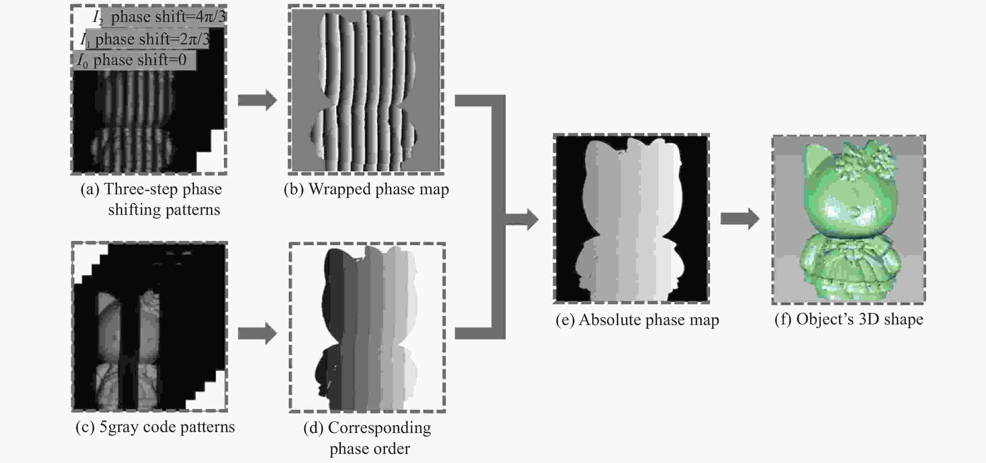
Figure 1. Schematic diagram of conventional high-speed 3D measurement
图1(a)表示相机实际采集得到三帧相移光栅图像,具体可描述为[3]:
式中:n = 1,2,···,N表示相移步数;
$(x,y)$ 为像素坐标;${B_0}$ 为背景光强;${B_k}$ 表示第k阶高次谐波的幅度信息;${\phi _n}$ 为耦合相位,可描述为:式中:
$\phi $ 是理想相位信息;${\delta _n}$ 为第n帧条纹相移量,具体为:为了简化起见,下文省略像素坐标
$(x,y)$ 。图1(b)为采用相移算法计算所得真实相位
${\phi ^C}$ ,通常采用最小二乘方法实现[6]:由于采集条纹中含有高次谐波,真实相位信息中会引入相位误差形如[3]:
式中:
$B_{mN}^{ - 1}{\rm{ = }}B_{mN{\rm{ + }}1}^{} - B_{mN - 1}^{}$ ;$B_{mN}^{{\rm{ + }}1}{\rm{ = }}B_{mN{\rm{ + }}1}^{}{\rm{ + }}B_{mN - 1}^{}$ 。该类型相位误差会给实际三维测量带来不可忽略的测量误差。上述过程求解得到的相位信息
${\phi ^C}$ 是在(−π,π]范围内的一系列呈锯齿状不连续分布相位。为了获得物体的绝对相位$\varPhi$ ,需要对${\phi ^C}$ 进行相位展开,相位解包裹的方法有时域法和空域法,如图1(c)文中使用格雷编码法展开包裹相位[10]:式中:
$K$ 是对图像进行解码确定的相移条纹的级次信息,如图1(d)。最后,利用标定后的系统参数就可以从绝对相位中得到图1(f)的物体的三维信息[11-13]。 -
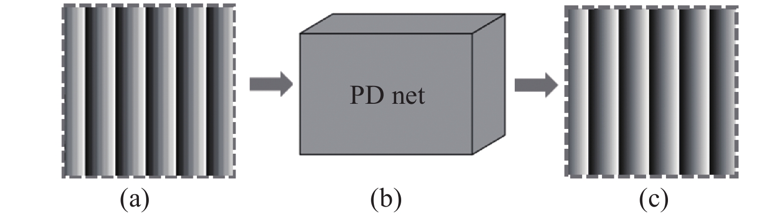
旨在轻微离焦程度下减少以致削弱高次谐波引入的测量误差,实现精确相位获取,进而实现快速精确三维测量,提出了基于深度学习精确相位获取的离焦投影三维测量方法,所提方法中使用深度学习实现精确相位获取的流程如图2所示。
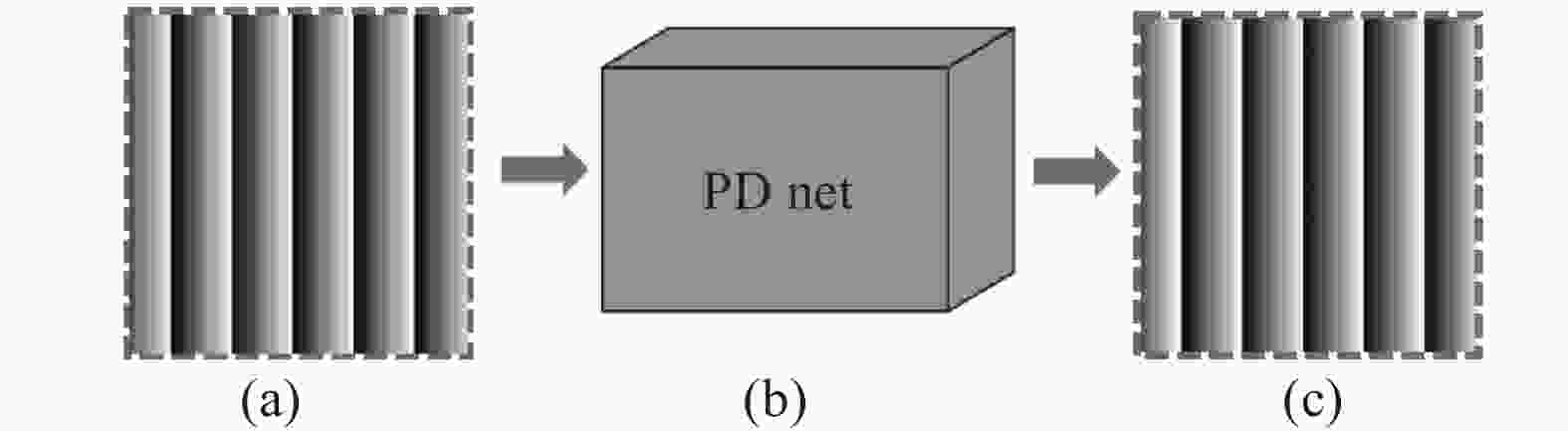
Figure 2. Schematic of accurate phase acquisition. (a) Phase with noise;(b) proposed PDNet;(c) result by the proposed method
与传统快速三维测量方法相比,所提方法在测量过程中引入基于深度学习的PDNet算法对包裹相位进行计算以得到精确相位信息。引入的PDNet算法构建含噪声相位
${\phi ^C}$ 到近似无噪声理想相位$\phi $ 的端到端方式训练模型,训练过程中算法每次迭代计算出的精确相位$\phi _i^{out}$ 与理想相位图像$\phi $ 进行残差学习将产生的误差返回到网络中,使网络不断迭代,得到一个最优的网络参数,使其具有较好的去噪能力同时对不同程度的噪声具有较好的鲁棒性。文中使用的误差函数如下式:式中:
$\phi _i^{{\rm{out}}}$ 为PDNet训练过程中每次迭代计算得到的相位图像,i为迭代次数,$\phi $ 为理想相位图像;m为相位图像中有效像素个数。最终,训练完成后利用得到的PDNet模型能够对不同场景下获取的相位图像${\phi ^C}$ 进行去噪,以得到测量所需精确相位图像${\phi ^{{\rm{out}}}}$ 。投影设备轻微离焦程度下,实际测量过程中仅需30次以下高次谐波影响,根据方波误差分布规律,投影十五步高频二值方波条纹,即可得到理想相位
$\phi $ 。对应的输入含噪声相位图像${\phi ^C}$ 即可选取三步相移算法求解得到。使用训练后得到的PDNet模型对输入相位图像${\phi ^C}$ 进行运算即可得到精确相位图像${\phi ^{{\rm{out}}}}$ ,精确相位图像${\phi ^{{\rm{out}}}}$ 与理想相位图像$\phi $ 之间存在的相位误差可用$\Delta \phi _{}^{{\rm{out}}}$ 表示,可简单用数学描述为:据此式即可进行相位误差评估。依据去噪后的精确相位
${\phi ^{{\rm{out}}}}$ 即可得到物体的准确三维信息。如图2所示,PDNet算法训练完成后使用模型就能够在测量过程中将图2(a)含有噪声的相位图像
${\phi ^C}$ 作为输入层计算,得到去噪后的精确相位图像${\phi ^{{\rm{out}}}}$ ,如图2(c)所示。图2(b)为引入的PDNet,具体结构见图3。
Figure 3. Structure of the PDNet
如图3所示,对于网络结构的设计,文中借鉴了高效残差分解网络(Efficient Residual Factorized Network,ERFNet)[14],在其基础上对网络结构进行了改进,增加了跳层连接并去掉了池化层,以更好地匹配文中的图像去噪任务。因为增加跳层可以更好地进行残差学习,利于噪声的去除,而池化层则可能导致图像丢失细节信息,内部的网络层均由特征图所构成。编码过程和解码过程都含有多尺寸的卷积层与相关的策略层,其主要模块及相关参数设置如表1所示。表1中,“Out-F”为输出图层通道数,“Out-Res”为假设输入尺寸为1 024×512时各层的输出分辨率。
Type Out-F Out-Res ENCODER 1 Downsampler block 16 512×256 2 Downsampler block 64 256×128 3−7 5 × Non-bt-1D 64 256×128 8 Downsampler block 128 128×64 9 Non-bt-1D(dilated 2) 128 128×64 10 Non-bt-1D(dilated 4) 128 128×64 11 Non-bt-1D(dilated 8) 128 128×64 12 Non-bt-1D(dilated 16) 128 128×64 13 Non-bt-1D(dilated 2) 128 128×64 14 Non-bt-1D(dilated 4) 128 128×64 15 Non-bt-1D(dilated 8) 128 128×64 16 Non-bt-1D(dilated 16) 128 128×64 DECODER 17 Deconvolution (unsampling) 64 256×128 18−19 2 × Non-bt-1D 64 256×128 20 Deconvolution (unsampling) 16 512×256 21−22 2 × Non-bt-1D 16 512×256 23 Deconvolution (unsampling) C 1 024×512 Table 1. Main network modules and parameters
该网络模型结构主要包含三个模块:Downsampler block,Non-bt-1D(dilated),Deconvolution (unsampling):
(1) Downsampler block
该模块包括:卷积核大小3×3的卷积层,并根据参数设置输入及输出的特征图通道数,用于获取噪声图的特征分布;BN层(Batch Normalization),可防止梯度消失或爆炸;ReLu激活层,也可克服梯度消失的问题并通过特征稀疏性加快网络速度。
(2) Non-bt-1D(dilation rate)
该模块包括:两层卷积核大小3×1的卷积层,两层卷积核大小1×3的卷积层,并可设置卷积核的间隔数量(dilation rate),形成空洞卷积以增大感受野,两层BN层,还包括dropout策略,即在前向传播的时候,让某个神经元的激活值以一定的概率停止工作,使得它不会太依赖某些局部的特征,这样可以使模型泛化性更强。
(3) Deconvolution (unsampling)
此模块主要包括一层卷积层、BN层和ReLu激活层,该模块主要目的是为了对特征进行上采样,最终恢复出与原图相同尺寸的目标输出图。
-
该节在模拟环境下验证所提方法。选取的二值方波条纹尺寸为400×400像素,周期在[48,78]之间,使用高斯低通滤波来模拟离焦,标准差
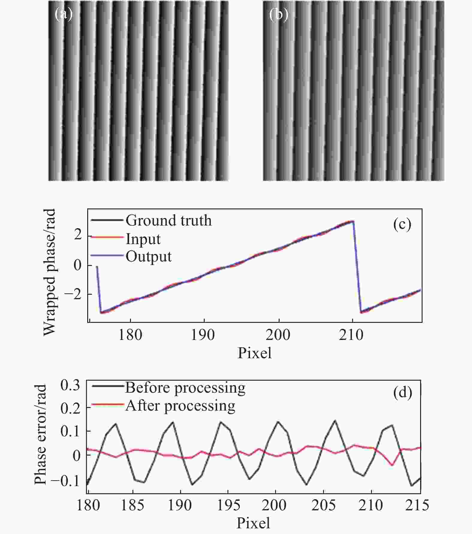
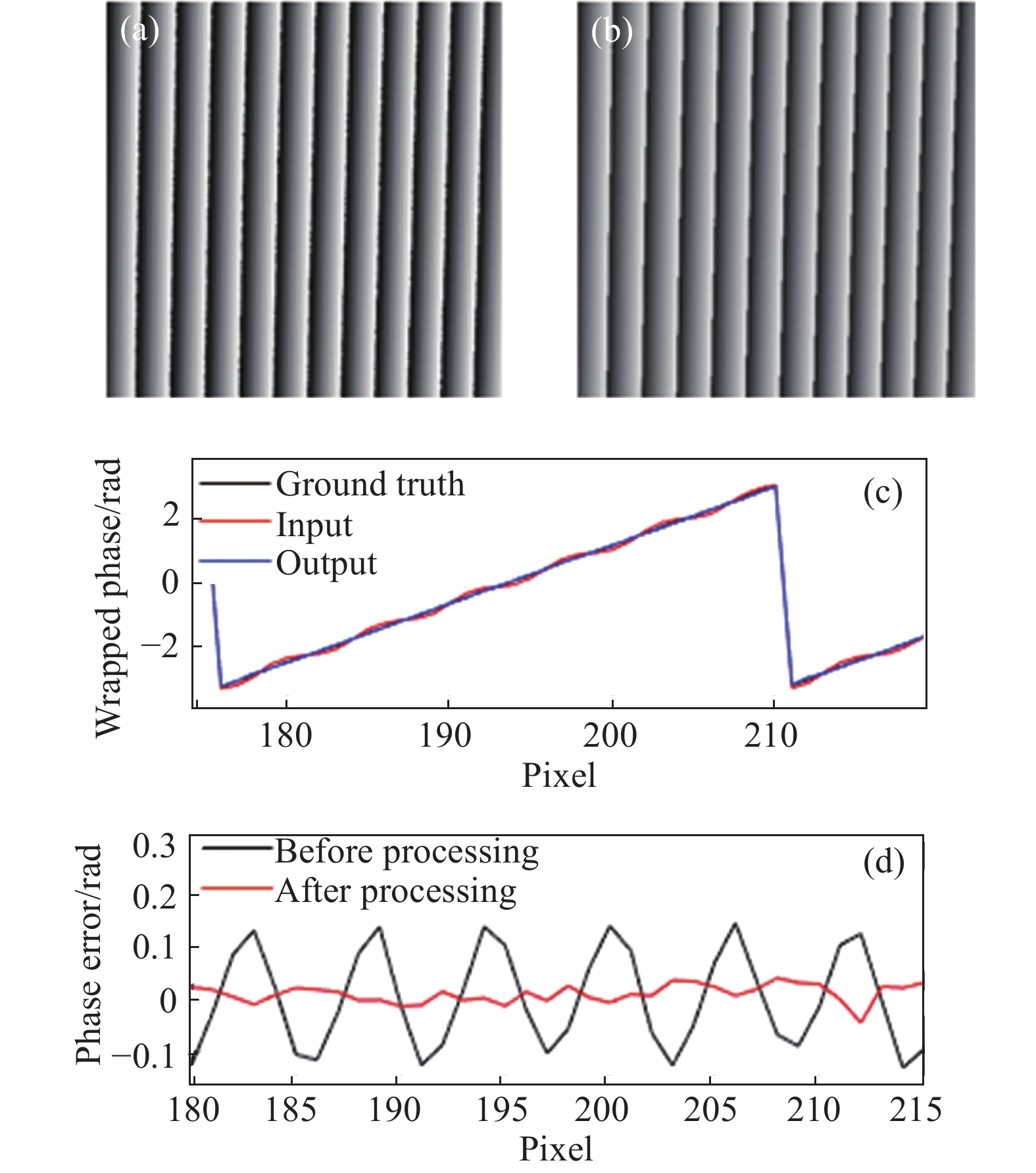
$\sigma $ 的范围在[2,5]之间,使用的高斯低通滤波器大小设定为$[6\sigma ] \times [6\sigma ]$ 。通过选取合适的方波条纹周期和高斯低通滤波器的标准差,以三步相移方波条纹仿真求解得到的包裹相位图像为输入,十五步相移方波条纹仿真求解得到的相位图像为近似理想相位,最终生成140组对应的包裹相位图像,其中100组作为训练集,验证集和测试集各20组。在图4中,选择周期T = 60的二值方波条纹,即30个黑色像素加30个白色像素,对其进行仿真来验证所提方法。图4(a)为输入带有噪声的相位图像,图4 (b)是使用所提方法预测出的相位图像,从视觉对比可以看出高次谐波引起的噪声在相位图像中明显降低。为了更精确对比去噪效果,图4(c)展示了去噪前后以及理想相位图像第100行像素中部分细节信息对比,图4(d)展示了图4(a)与图4(b)各自减去理想相位图像后第100行像素的部分误差曲线图。图4(c)展示了使用所提方法处理后的结果与理想相位图像更为接近,图4(d)展示了使用所提方法处理后的误差曲线更接近零,计算其MAE可知所提方法将相位噪声从0.108 6 rad降至0.020 2 rad,去噪效果显著。
为了验证所提方法在不同周期条纹下的表现,文中分别计算了模拟数据中周期T=48,54,60,66,72以及78的相位图像误差MAE数值并绘制误差曲线,如图5所示。由MAE误差曲线对比可得,文中所提出的方法对于不同周期相位图像具有良好的一致性效果。
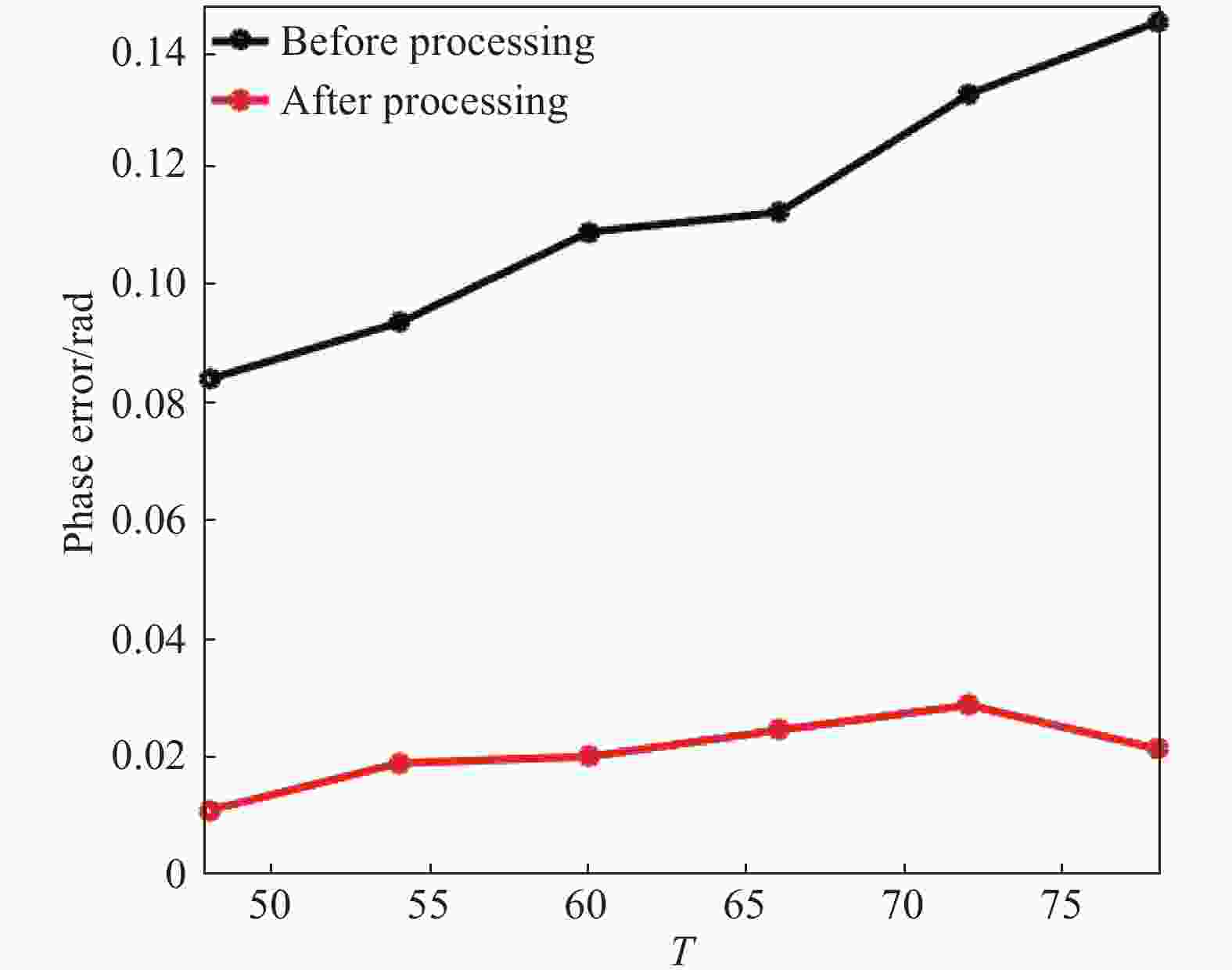
Figure 5. Phase error of simulated wrapped phase at T = 48,54,60,66,72,78
-
该节在实际构建系统中验证所提方法。所构建测量系统主要包括DLP6500投影仪,带有8 mm焦距镜头的Basler acA800-510um CMOS相机,以及一台使用TITAN RTX(NVIDIA)进行运算加速的计算机。
真实数据集共采集580组真实场景,选取500组真实场景作为训练集,验证集和测试集各40组。真实数据集中输入和近似理想相位图像分别为离焦投影三步和十五步二值方波条纹并使用相移算法求解得到的包裹相位图像,图像的大小为400 × 400像素,投影所用二值方波光栅的周期仍在[48,78]之间。
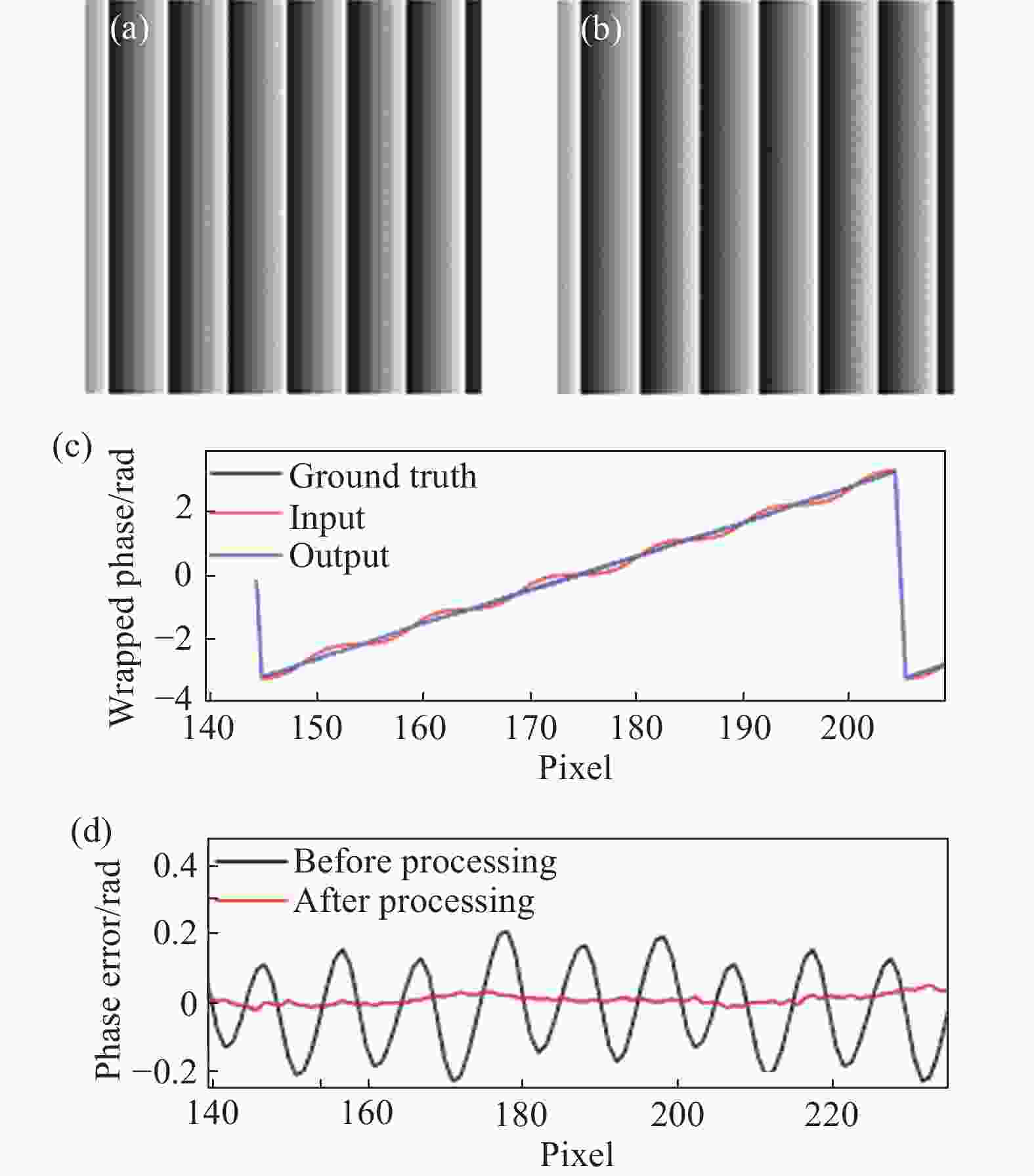
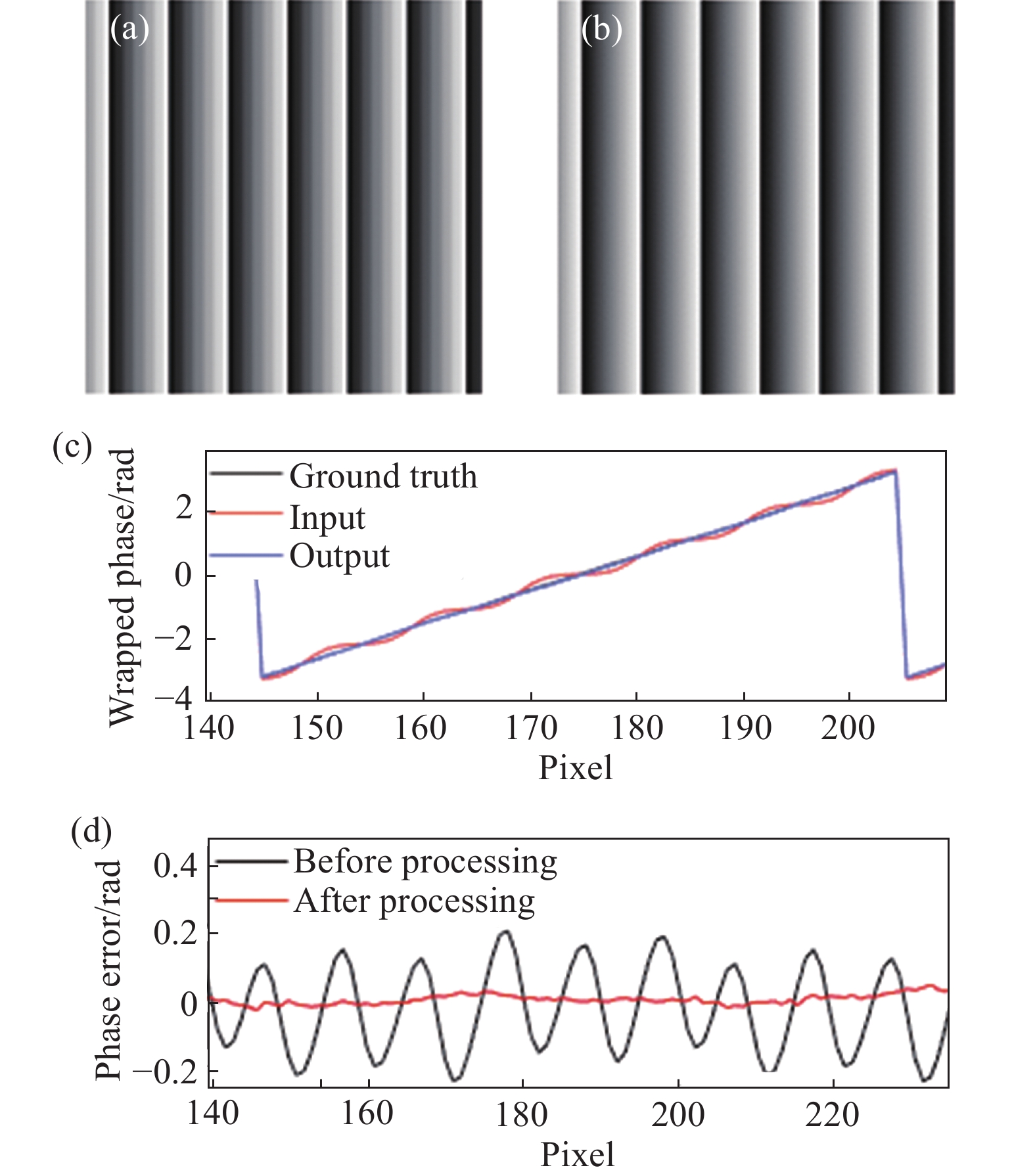
首先选取了白色墙面作为目标物体,投影周期在[48,78]之间的二值方波条纹进行测量。文中选取投影周期T=60的二值方波条纹计算得到的包裹相位图像进行分析。图6(a)是输入带有噪声的相位图像,图6(b)是使用所提方法得到的精确相位图像。由视觉对比可以明显看出使用所提方法得到的精确相位图像,与含有噪声的相位图像相比更加平滑,计算其MAE数值可知,所提方法将相位噪声从0.156 5 rad降至0.018 8 rad。
为了进一步对比去噪表现,图6(c)展示了图6(a)、图6(b)与理想相位图像第100行部分细节对比,可以清楚看出使用所提方法得到结果与理想结果更为接近。图6(d)展示了图6(a)与图6(b)各自减去理想相位后第100行部分误差曲线图。红色表示使用所提方法处理后的误差曲线,该方法能够将误差降低至随机噪声水平。
为了分析所提方法在实际测量情况下投影不同周期条纹时的表现,同样绘制周期T=48,54,60,66,72以及78的相位图像MAE误差曲线,如图7所示。由MAE误差曲线对比可得,文中所提方法在实际测量中投影不同周期相位图像同样表现出良好的一致性效果。
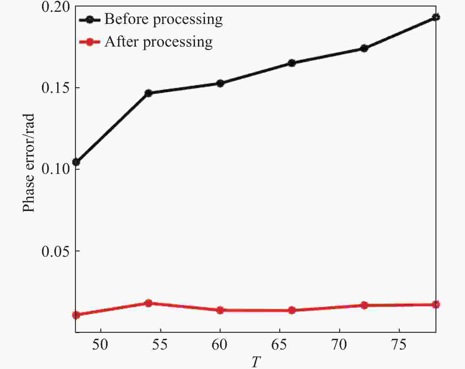
Figure 7. Phase error of actual measurement of wrapped phase at T = 48, 54, 60, 66, 72, 78
其次选取玩具模型作为目标物体进行三维重建,使用所提方法对投影三步二值方波条纹计算得到的的包裹相位图像去噪前后效果如图8(a)~8(b)所示。为了更准确地评估文中所提方法的效果,对处理前后的包裹相位做了误差对比,如图8(c)~8(d)所示,由误差对比可以看出虽然在边缘以及细节处仍存在部分误差,但整体去噪效果显著。此外,还计算了误差去除前后的相位误差MAE数值,处理前为0.036 7 rad,处理后为0.024 6 rad。

Figure 8. Wrapping phase map before and after denoising and its error comparison. (a) Phase map with noise;(b) result by the proposed method;(c) phase error before denoising;(d) phase error after denoising
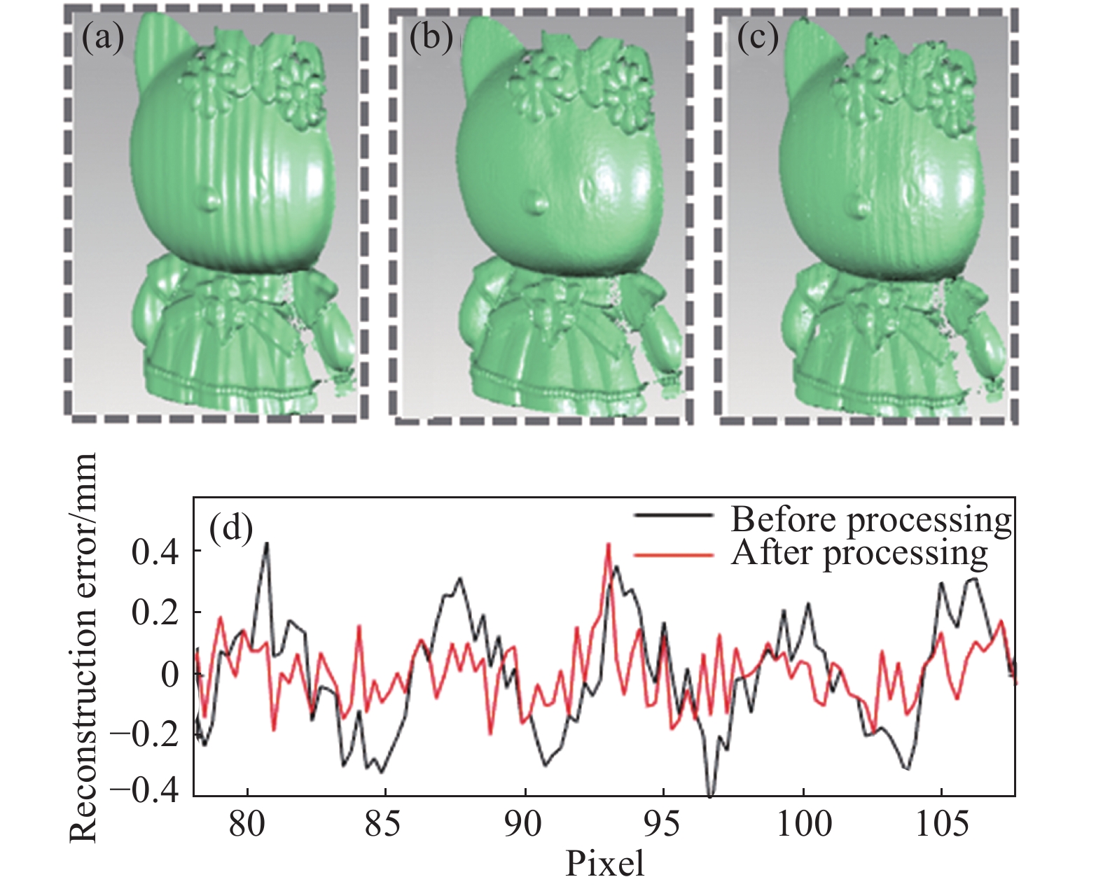
从图8中物体的相位误差对比结果可知,所提方法去噪效果显著。为了更进一步检验去噪效果,文中分别比较了使用所提方法处理前后相位图像的重建效果,如图9所示。图9(a)与图9(b)分别为三步和十五步相移条纹求解相位的重建效果,图9(c)为使用所提方法对三步相移条纹处理后的重建结果。从视觉对比可以明显看出图9(a)的重建结果受高次谐波干扰较大,经过所提方法处理后的重建结果与近似理想重建结果较吻合。为了更准确说明所提方法的效果,将去噪前后物体三维坐标深度信息与对应近似理想结果相减得到误差曲线,如图9(d)所示。计算其MAE数值可知,使用所提方法将高次谐波引起的重建误差从0.161 2 mm降至0.089 6 mm。可以进一步得出结论,文中所提的快速测量方法能够有效较低高次谐波带来的干扰。综上,从模拟和真实数据均验证了所提快速测量方法的有效性和精确性。
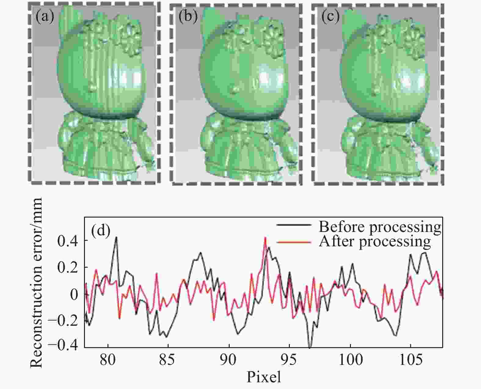
Figure 9. Comparison of reconstruction results. (a) Reconstruction results before processing using the proposed method;(b) ideal reconstruction results;(c) reconstruction result by the proposed method;(d) reconstruction error curve
-
在传统快速三维测量基础上,提出一种降低高次谐波引起相位噪声的快速三维测量方法。所提方法的明显优势在于,能够在不增加额外投影光栅帧数前提下,实现轻微离焦程度下精确相位信息获取,结合已标定系统参数,即可进行精确快速三维重建。与现有快速三维测量方法相比,该方法能够在不牺牲测量速度的前提下保证测量精度。采用该方法对模拟数据和真实墙面进行验证分析。结果表明,该方法对于不同周期相移条纹计算得到的相位图像均能得到高质量相位图像,且去噪效果稳定,证明该方法的有效性。此外,文中还对真实玩具模型进行验证,对比处理前后的重建效果,证明该方法的精确性。另外,在实际测量中,仅需使用数据集训练后得到的模型,无需修改任何参数信息,即可实现不同离焦程度下的精确三维重建。
Defocus projection three-dimensional measurement based on deep learning accurate phase acquisition
doi: 10.3788/IRLA20200012
- Received Date: 2020-04-13
- Rev Recd Date: 2020-05-22
- Available Online: 2020-07-23
- Publish Date: 2020-07-23
-
Key words:
- 3D measurement /
- defocused projection /
- deep learning /
- accurate phase
Abstract: The digital fringe projection three-dimensional (3D) measurement technology can generate a sinusoidal fringe pattern for 3D measurement by defocusing a binary fringe pattern. It can achieve extremely high projection speed and has great potential in the field of high-speed 3D measurement. However, the binary fringe pattern inevitably contains higher-order harmonics, resulting in a phase error introduced into the calculated phase, thereby reducing the accuracy of high-speed 3D measurement. A 3D measurement method for defocused projection based on deep learning accurate phase acquisition was proposed. The image feature processing capability based on deep learning algorithm can remove the phase errors introduced by higher-order harmonics. An end-to-end deep convolutional neural network from noise phase to precise phase was constructed by this method and the phase error introduced by higher-order harmonics was reduced. Finally, high-speed and accurate 3D measurement could be achieved by this method. Firstly, the theoretical analysis proved the feasibility of the proposed method. Then, simulation and experiments were performed to further verify the effectiveness and accuracy of the proposed method. Compared with the existing high-speed 3D measurement methods, the proposed method can ensure measurement speed while ensuring measurement accuracy.


 DownLoad: