


-
对地观测卫星正日益从大型(耗资几百亿美元)观测平台转变为由高精尖的光学、电子和材料技术制造的微纳遥感卫星方向发展,这些尖端制造技术可以提供更短的研制周期,更低的成本以及更加可靠的性能[1]。目前最流行的小卫星种类划分方法由英国萨瑞大学提出,质量在10~100 kg范围以内的卫星为微型卫星,质量在10 kg以内的卫星为纳卫星。微纳卫星可以通过加强组网,缩短重访周期,完成对全球任意目标的准实时观察,根据用户的要求灵活部署,这些是传统大型遥感卫星难以做到的,使卫星遥感的性价比大为提升[2-4]。
美国Planets Lab公司的Skysat系列卫星,总规模达21颗,每颗质量100 kg左右,分辨率在0.5~1 m量级。该公司的“鸽群”遥感卫星星座是由约350颗卫星组成,每颗卫星质量5 kg左右,地面分辨率为3~5 m,该星座是全球最大规模的地球遥感卫星群[5]。我国商业航天遥感以“吉林一号”卫星星座为代表,目前已在轨29颗各类型光学遥感卫星,并首次在国内推广视频遥感卫星的应用[6]。
针对空间相机的轻量化和稳定性要求,研究人员广泛采用先进航天材料,并结合形状、尺寸及拓扑等结构优化设计方法对相机进行设计[7-8]。空间相机的研制涵盖光学、机械、热学等多个学科[9],随着空间相机轻量化程度要求的不断提高,其设计越来越富有挑战性[10-11]。而多学科优化设计技术,在处理复杂耦合系统的多目标优化设计方面具有突出的优点[12-13],特别适用于微纳卫星和空间相机的设计[13-14]。目前,国内外已将光机集成仿真方法应用于空间相机的系统性能闭环分析[15-19],而进行集成优化设计的研究与应用相对较少。
文中所研究的光学遥感载荷搭载于20 kg级微纳视频卫星,该星是包括普查、详查、多光谱等遥感卫星在内的微纳卫星星座的重要组成部分,该星座主要用于验证在轨交付、编队飞行、任务协同等对地应急遥感关键技术。该视频相机在500 km轨道上,地面像元分辨率优于1.5 m,幅宽大于10 km的性能指标下,质量要控制在5 kg以内,实现光机结构的超轻高稳定性设计成为该相机最具挑战性的任务之一。文中在阐述该相机关键设计环节的同时,重点介绍了其进行光机结构设计所采用的以系统波像差和视轴稳定误差为目标的光机集成优化方法,在实现轻量化设计的同时来保证相机的成像质量和稳定性,并对相机研制过程中的装调和试验环节进行了介绍。
-
微纳视频卫星主要由综合电子、姿态与轨道控制、电源与总体电路、结构与机构、热控、视频相机等分系统组成。卫星运行在500 km高度的太阳同步轨道上,采用三轴稳定技术,实现对日定向、对地推扫、对地凝视等姿态控制模式。卫星结构采用串联式总体布局,充分考虑载荷的支撑和力学特性,采用箱体式卫星结构为视频相机提供了良好的动力学环境和热环境,同时在舱内紧密布置了各分系统,以高功能集成化和质心最低为核心目标,有效减小了相机的动力学环境,便于批量化装配和降低生产成本。整星尺寸为740 mm×380 mm×380 mm(发射状态),视频星模型如图1所示。

Figure 1. (a) Launching mode; (b) On orbit operating mode
根据遥感星座的总体任务要求,其所搭载的相机应具备框幅式推扫成像和高帧频视频成像两种任务能力。为了实现推扫及视频两种成像功能,并具有较高的星下点分辨率,选用辰芯公司的GMAX1205 CMOS作为相机的图像传感器,其有效像元数为12 000 H ×5 000 V,像元尺寸为5.5 μm×5.5 μm,功耗1.5 W。根据相机指标要求和所选传感器,相机光学参数设计为焦距1 850 mm,视场角1.64°。
-
分析了折射式、折反射式和全反射式等光学系统结构的特点后,该相机采用了同轴两反加校正镜的光学系统。在焦距一定的情况下,口径的变化即为相对孔径的变化,相对孔径越小,衍射极限越低,奈奎斯特频率处的调制传递函数值也越小。此外,信噪比与相对孔径值的二次方成正比。为了保证足够高的衍射极限和信噪比,并且平衡相机的尺寸和质量,最终选择光学系统通光口径为Ф210 mm,F数为8.8,星下点分辨率为1.48 m。光学元件布局如图2所示,其中主镜和次镜均采用偶次非球面,四片校正镜用于校正轴外像差,同时为了降低空间辐射的影响,校正镜组前采用熔石英平板玻璃进行防护。光学设计的调制传递函数曲线如图3所示,探测器奈奎斯特频率(91 lp/mm)处的全视场全波段平均值为0.28。此外,主要光学元件的偏心和倾斜的公差分别是10 μm和20″。

Figure 2. Layout of optical elements

Figure 3. MTF curve
-
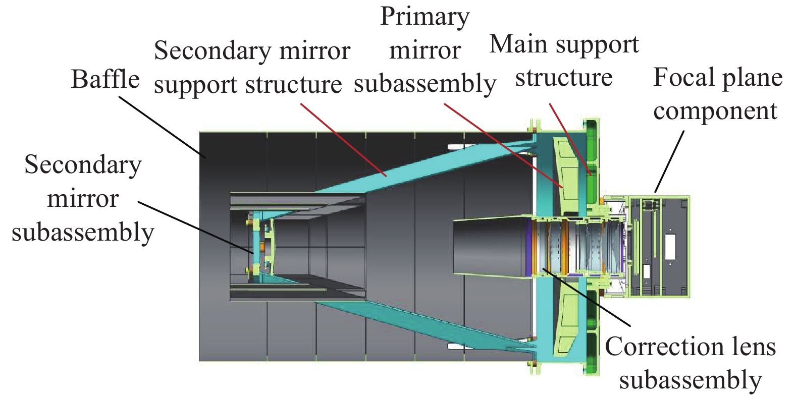
如图4所示,相机主要的光学元件为主反射镜和次反射镜,为了获得轻量化、高稳定的光机结构设计,来保证相机的在轨成像性能,主镜和次镜均采用碳化硅材料,碳化硅材料具有比刚度高、热膨胀系数小以及导热性能良好的优点。主、次镜均通过柔性支撑安装在主承力结构上,柔性支撑材料选用与碳化硅材料线胀系数一致的殷钢制造。
主承力结构是相机的主要支撑部件,是主、次镜位置精度的重要保证,主承力结构分为次镜主支撑结构和主背板。次镜主支撑结构由三根桁架杆和薄壁筒组成,为次反射镜提供安装定位接口;整个桁架结构一体化设计、加工,材料选用铝合金。主背板除了为主反射镜提供安装定位接口外,还为次镜主支撑结构、外遮光罩、校正组件和焦面组件等提供了支撑和定位,采用了碳化硅材料进行设计。校正镜组件的各透镜安装在铝合金镜筒中,并固定在主背板上。
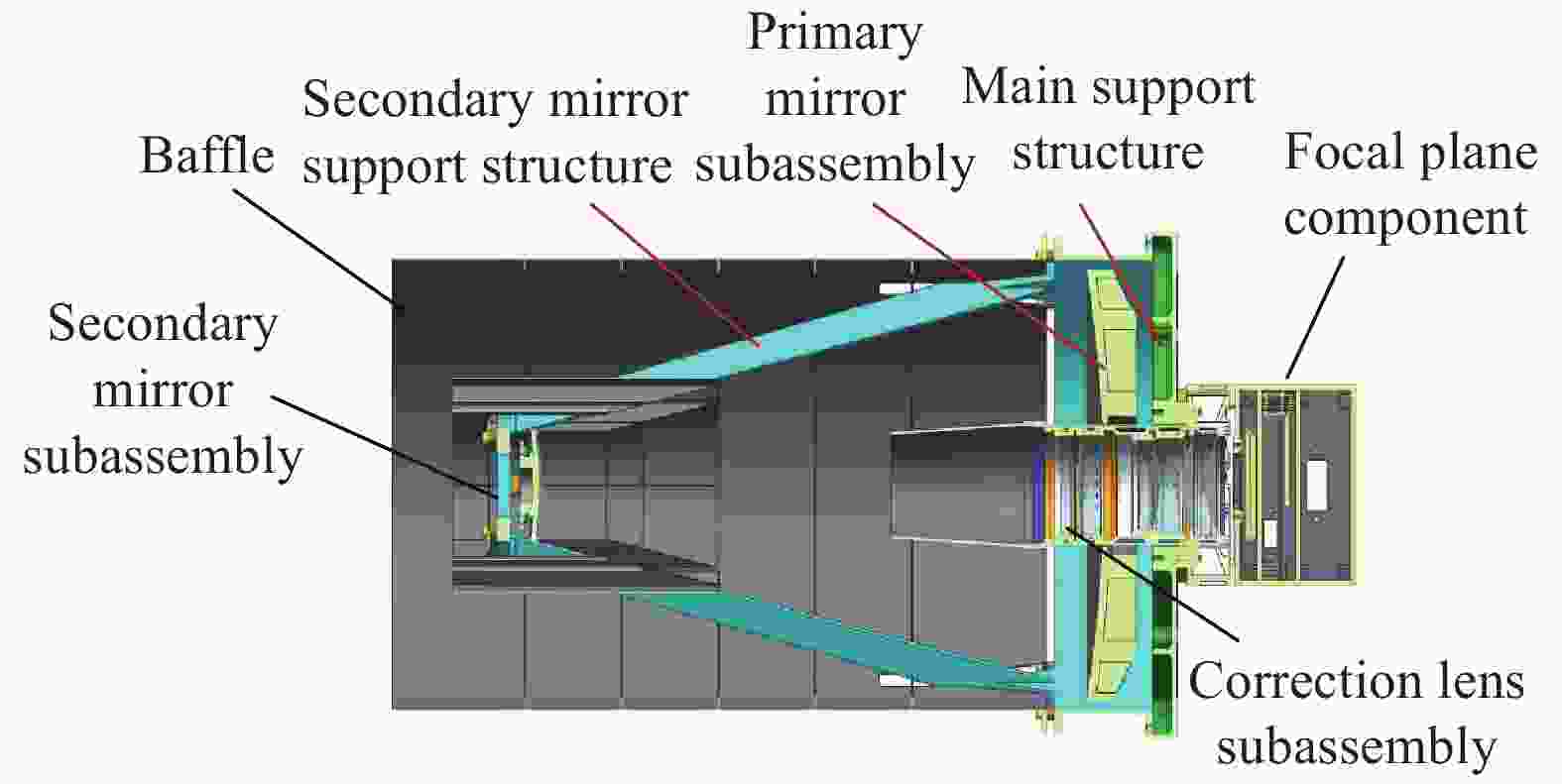
Figure 4. Optomechanical structure of camera
-
相机与成像性能和稳定性相关的两个主要指标包括:系统波前误差是光学系统的实际波面与理想波面之间的偏差,反映了光学系统的成像质量;视轴稳定性误差是外界载荷作用下物体在光学系统像面上的成像位置变化,反映了系统指向精度的稳定性[20]。在设计过程中,为了使光机结构能够在满足这两项相机性能要求的同时,实现最优的结构尺寸参数设计,从而具有较高的轻量化率,使用了光机集成分析与优化技术进行了优化设计。
将光机结构的关键尺寸参数作为优化设计变量,将质量、视轴稳定性误差和系统波前误差最小作为目标。与此同时,为避免火箭发射过程中产生共振现象对结构造成破坏,约束结构的一阶固有频率不小于100 Hz。有限元模型如图5所示。建立次镜主支撑结构和主反射镜的集成优化数学模型表示为:
式中:Li为次镜主支撑结构和主反射镜的关键尺寸参数,设置为优化的设计变量;L1~L4分别代表反射镜背板加强筋厚度、支撑孔壁厚、加强筋间距和边缘材料切除高度;L5和L6代表主支撑结构的支撑杆厚度和底部安装面厚度;f1为结构第一阶固有频率,f1≥100 Hz;MASS、LOS和WFE分别为结构质量、相机的视轴稳定性误差和系统波前误差,设置为尺寸优化模型的目标。

Figure 5. FE model of optomechanical structure
此外,由于主背板处于相机的最底部,主要对主反射镜的面形误差以及整机的固有频率具有较大影响,因此,首先开展了主背板以主镜面形误差为主要指标的优化设计。主镜的面形误差需要考虑加工和检测两种状态,在优化模型中将平行光轴方向面形误差作为约束,约束其不大于5 nm;将垂直光轴方向面形误差最小设为目标,尽量提高其面形稳定性,则背板的优化模型为:
式中:Pi为背板的结构尺寸参数;P1~P3分别代表了背板的厚度、高度、加强筋厚度,并且每个尺寸应控制在一定的尺寸范围内
$\underline {{P_i}} \leqslant {P_i} \leqslant {\overline P _i}$ 进行优化;RMSX和RMSZ分别代表主反射镜在水平和竖直重力作用下的面形畸变的RMS值。根据材料的制造工艺性和设计经验制定边界约束条件:1.5≤P1≤4.5,7.0≤P2≤20.0,2.5≤P3≤7.5。 -
采用适用多目标、复杂目标函数、高度非线性和非连续设计空间的第二代非序列排序遗传算法(NSGA-Ⅱ)对参数进行优化。通过多学科软件集成,调用NSGA-Ⅱ算法迭代寻优,求得尺寸参数多目标优化的最优解。主镜和主支撑结构主要尺寸优化结果如表1所示,主反射镜的质量由1.241 kg减小到0.561 kg,次镜主支撑结构的质量由1.109 kg减小到0.577 kg。主背板在满足面形误差设计要求的前提下,背板的厚度、高度及加强筋厚度初始尺寸分别为3、13.5、5 mm,经优化后尺寸分别为2.0、9.6、2.2 mm,质量由1.054 kg减小到0.591 kg。含主镜组件、次镜组件、遮光罩组件、校正镜组件、次镜主支撑结构及主背板在内的光机结构总重仅3.03 kg。
Parameters L1 L2 L3 L4 L5 L6 Initial values 3.0 5.0 30.0 15.0 5.0 5.0 Optimized values 2.3 2.9 32.5 18.6 3.1 3.3 Table 1. Integrated optimization results of the primary mirror and main support structure(Unit: mm)
为了对设计结果进行验证,首先对整机进行静力学分析,在重力、均匀温升4 ℃以及安装不平度0.01 mm耦合工况下,主、次反射镜面形及偏心与倾斜如表2所示,其中偏心和倾斜均以主镜为基准。
Mirror Displacement RMS /nm Decenter/μm Tilt /(″) X Y X Y Primary 1.35 − − − − Secondary 1.03 7.22 4.13 14.87 2.19 Table 2. FEA results of coupling conditions
对优化后的相机进行约束模态分析,前两阶振型云图如图6所示,一阶模态为123.6 Hz,满足相机指标要求。
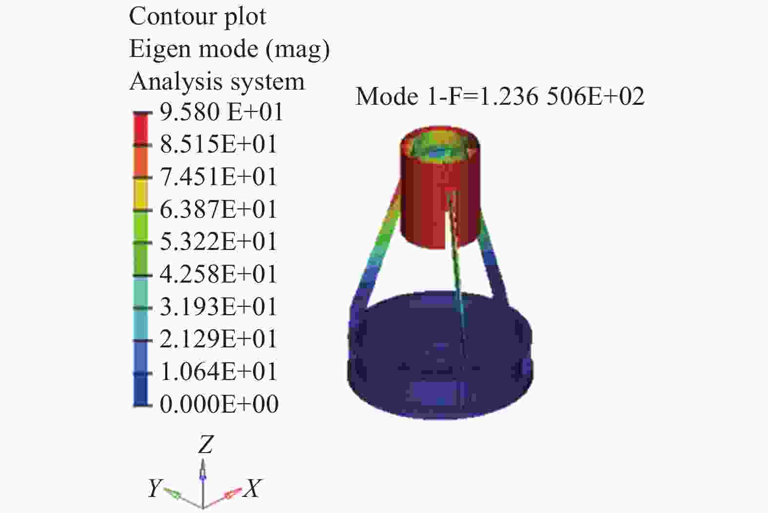
Figure 6. 1st modal shape
-
相机装调以主镜作为基准,调整其他光学元件,采用自准直干涉法来检验系统的波像差,通过监测波像差来对次镜进行调整,使系统达到最佳成像状态。采用定心车的方法来进行校正镜的装配,通过修研校正镜组件和背板之间的垫片来保证其位置精度要求。
-
空间相机是在地面1 g重力环境下制造、加工和装配的,相机进入工作轨道后的重力场几乎为零,这种重力的变化会引起光学元件发生刚体位移以及一定程度的面形畸变,这些变化会影响相机的成像质量[20]。在重力测试实验中,相机的光轴处于水平状态,分别进行了正向和反向重力工况下的波像差测试,其中反向重力工况为将相机倒置并在相机状态稳定后进行波像差测试,检测状态如图7所示。相机在两种状态下所承受的重力大小相等,方向相反,两种状态下的系统波前检测干涉云图如图8所示。在重力作用影响下,相机正向和反向重力工况下中心视场的系统波前误差RMS值均保持在0.06λ以内,且两种重力工况下中心视场的系统波前误差RMS变化量极小,表明了相机的静力学性能和稳定性良好。

Figure 7. Wavefront aberration measurement setup

Figure 8. (a) Wavefront aberration of positive gravity; (b) Wavefront aberration of negative gravity
-
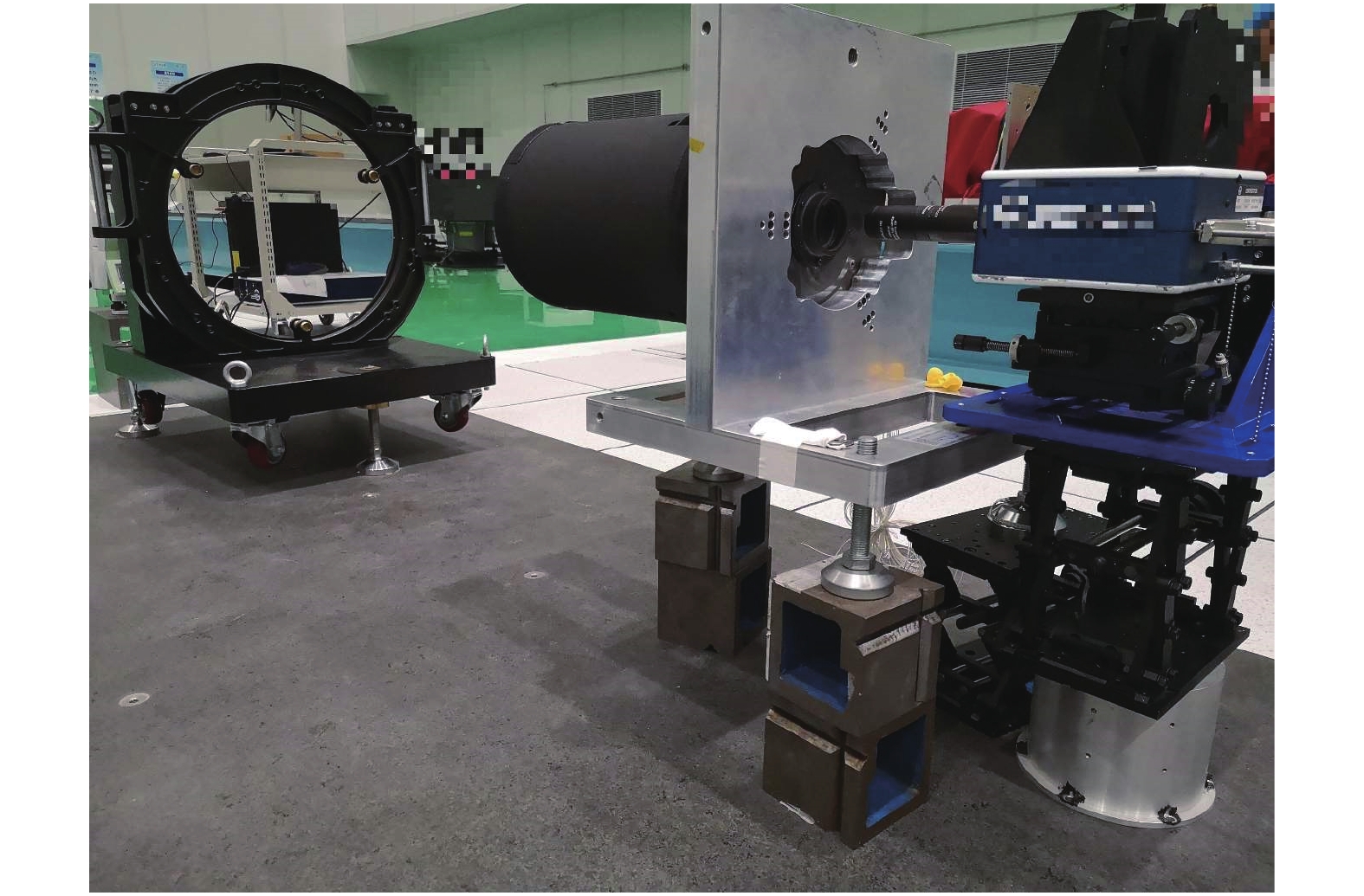
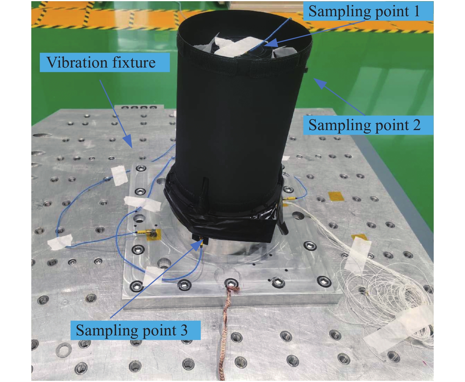
在相机装调及静力学试验后,对相机进行了振动试验,试验装置如图9所示。采样点1为相机次镜主支撑结构顶端,采样点2为相机外遮光罩的顶端边缘,采样点3为相机主背板的底部边缘。振动试验包括特征级扫频、正弦振动和随机振动试验。特征级试验参数为:三个方向扫描频率为5~2 000 Hz,振幅为0.1 g。正弦激励参数为:三个方向扫描频率为5~100 Hz,振幅为0.7 g,扫描率为4 oct/min。随机激励参数为:三个方向扫描频率为5~2 000 Hz,总均方根加速度值为1.2 g,持续2.0 min。

Figure 9. Vibration test of camera
两个水平方向的特征级试验的第一峰值出现在120 Hz附近,这与相机模态分析的一阶基频123.6 Hz接近,相差2.4%,验证了仿真分析模型的准确性,也表明结构具有足够高的刚度。振动试验后,相机的系统波像差及传递函数无明显变化。
-
文中研制了一种采用同轴两反加校正镜光学系统的微型空间遥感相机,焦距为1850 mm,通光口径为Ф210 mm,在500 km轨道高度下空间分辨率达到了1.48 m,并同时具备框幅式推扫和高帧频视频成像功能。光机结构设计采用了先进航天材料,并建立了以质量、系统波前误差和视轴稳定性误差最小为目标的集成优化模型。通过光机集成分析和优化设计,相机体积仅Φ254×482 mm,相机总质量仅4.76 kg,其中光机结构的质量仅3.03 kg,并通过地面力学试验验证了其力学性能和稳定性。
Optomechanical structure design and experiment of high-resolution video camera for micro-nano satellite(Invited)
doi: 10.3788/IRLA20210477
- Received Date: 2021-07-13
- Rev Recd Date: 2021-08-15
- Publish Date: 2021-10-20
-
Key words:
- camera structure /
- spaceborne video camera /
- optomechanical integrated optimization /
- micro-nano remote sensing satellite /
- mechanical performance
Abstract: The design, assembly and experiment of the optomechanical system of a compact spaceborne video camera developed for the 20 kg micro-nano optical remote sensing satellite were introduced, and the integrated optimization method was also proposed. The camera was a Cassegrain optical system including two mirrors and one corrector assembly. In order to obtain the best thermal stability, the mirrors were made of silicon carbide. Firstly, based on the task and overall design of 20 kg micro-nano video satellite, the requirements of video camera were proposed; Then, the optical and optomechanical structure system of the video camera were introduced respectively; In order to further improve the lightweight rate, while meeting the requirements of optical performance, the optomechanical integration optimization method was used to the lightweight design. After optimization, the mass of the optomechanical system was only 3.03 kg, the weight of the whole camera was only 4.76 kg, and the 1st mode was larger than 120 Hz; Finally, the assembly and ground mechanical experiments of the camera were summarized. The results showed that the camera had very dynamic properties and stability.


 DownLoad: