


-
光电编码器是以高精度计量圆光栅为检测元件,通过光通量变化,将角位置信息转换为数字代码的高精度非接触测量装置。具有测量精度高、体积小、质量轻和使用可靠等优点,广泛应用于雷达、光电经纬仪、数控机床及闭环调速系统等领域[1-2]。但编码器在实际生产过程中,存在光学码盘的光栅线刻划不均匀、编码器主轴与轴承配合间隙过大及安装偏心等问题,导致编码器经常出现误差或误码等情况,严重影响编码器的正常使用。光电编码器精度检测是控制编码器质量的重要一环,也是保证编码器高分辨力、高精度的必要条件[3-4]。
德国联邦物理技术研究院利用非均匀分布的16个读数头分析编码器误差,不确定度仅为0.01″,但存在同一位置对读数头测量误差的一致性要求较高的弊端[5];加拿大哥伦比亚大学和美国麻省理工学院利用记录精密转台的主轴转过单位空间角位移所用时间,检测编码器的细分误差,准确度为 ±0.5″,但在测量过程中对转台主轴的稳定性要求较高[6];意大利国家计量研究所利用双气浮轴承转台与双读数头,读取底座和转台角度差,检测精度可达 ±0.04″,但在测量过程中,对转台精度要求较高[7]。北京理工大学利用高精度蜗轮蜗杆减速器保证转台高精度和高分辨率,但检测效率相对较低[8]。中国科学院长春光学精密机械与物理研究所利用高精度的基准编码器与被检编码器同轴转动,采集并比较二者输出的角度信息,但检测精度受基准编码器精度限制[9];长春禹衡光学有限公司利用自准直仪与多面棱体作为角度基准,与多面棱体同轴的待检编码器对标,检测方便,但多面棱体检测点数有限,无法实现连续检测[10]。综上所述,采用高精度编码器或多面棱体作为角度基准的直接比较法,虽然操作简单、使用方便、成本低,但精度受角度基准限制,很难实现高精度或全圆周连续检测;采用高精度转台、光学或算法分析的方法能实现高分辨力和高精度检测,但检测装置成本高、结构复杂、检测周期长[10-12]。文中利用自准直仪与多面棱体的光学小角度测量原理,实现高精度角度测量;同时,利用转角互逆双轴转台,实现连续误差检测,设计了一种光学连续闭环的光电编码器误差检测系统,该系统检测精度高、不受角度基准限制、可实现连续误差检测,具有较好的市场推广价值。
-
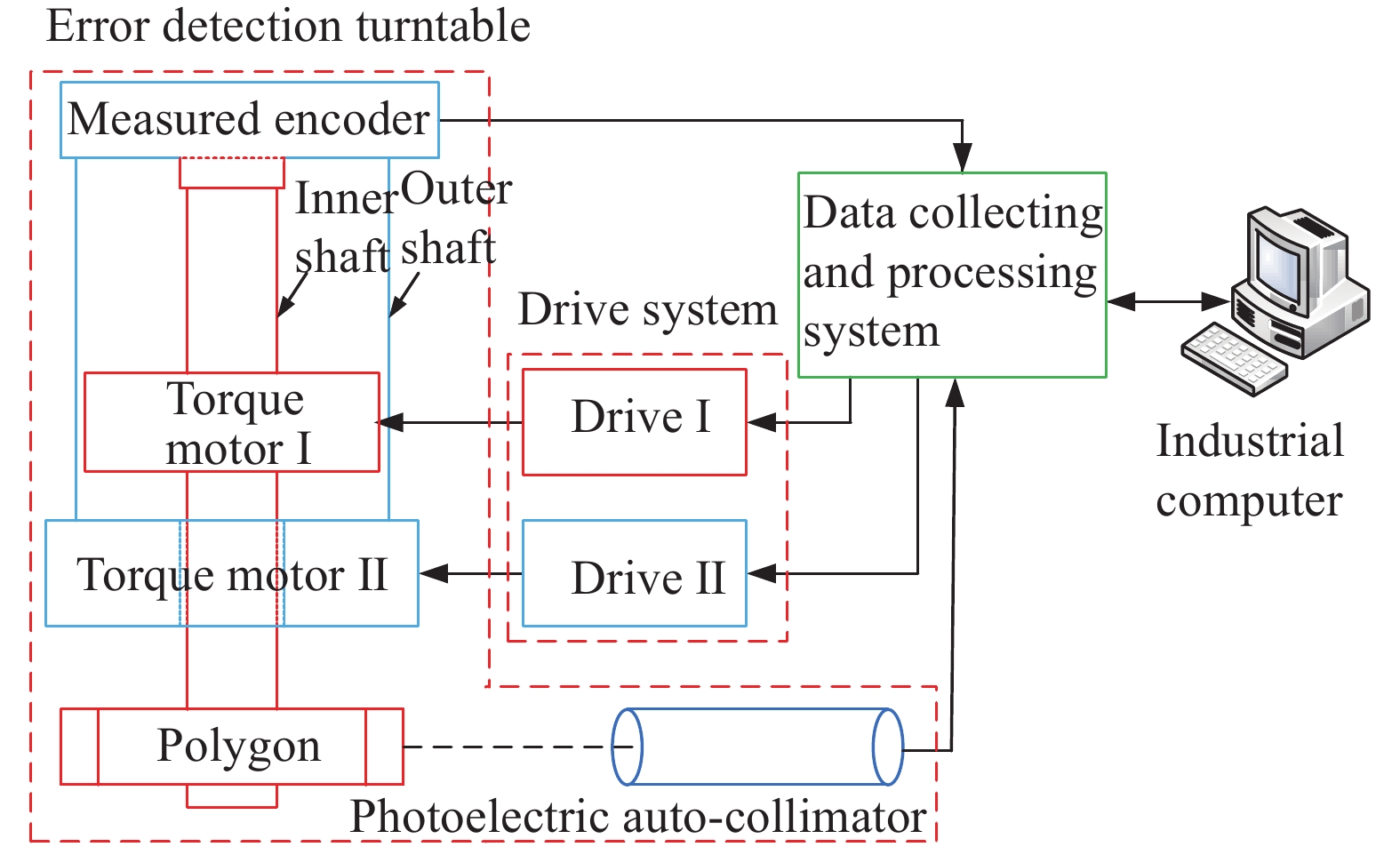
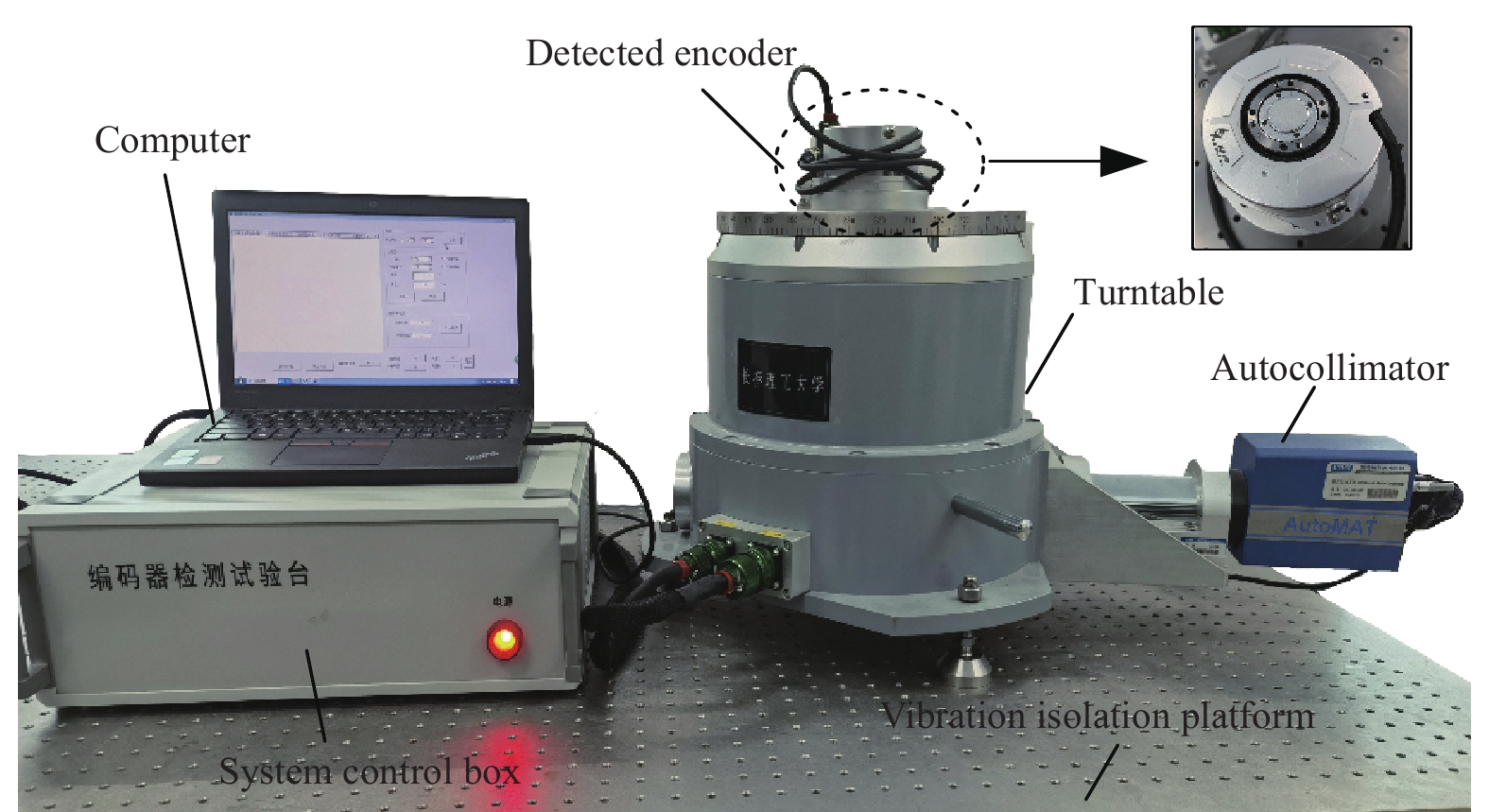
光学连续闭环误差检测系统利用光电自准直仪(奥特梅尔ULTRA- 3050 HR,分辨率:0.01″,精度:0.2″)与四面棱体(3级)的光学小角度测量原理,实现角度的高分辨率、高精度测量及转轴的回转位置反馈;利用双轴转台的内、外轴正反互逆和连续转动,实现全量程角度误差连续检测。该系统主要由光学误差检测转台、数据采集与处理系统、双轴驱动系统、计算机等组成,总体架构如图1所示。

Figure 1. System architecture
-
光学误差检测转台主要由自准直检测单元、双轴转台单元、校正反射镜单元和待检编码器组件组成。利用自准直初始化、工作系统回零、转角产生及检测、转角互逆、全量程检测和自准直复位等环节实现光电编码器高精度、全量程连续闭环检测,系统原理如图2所示。
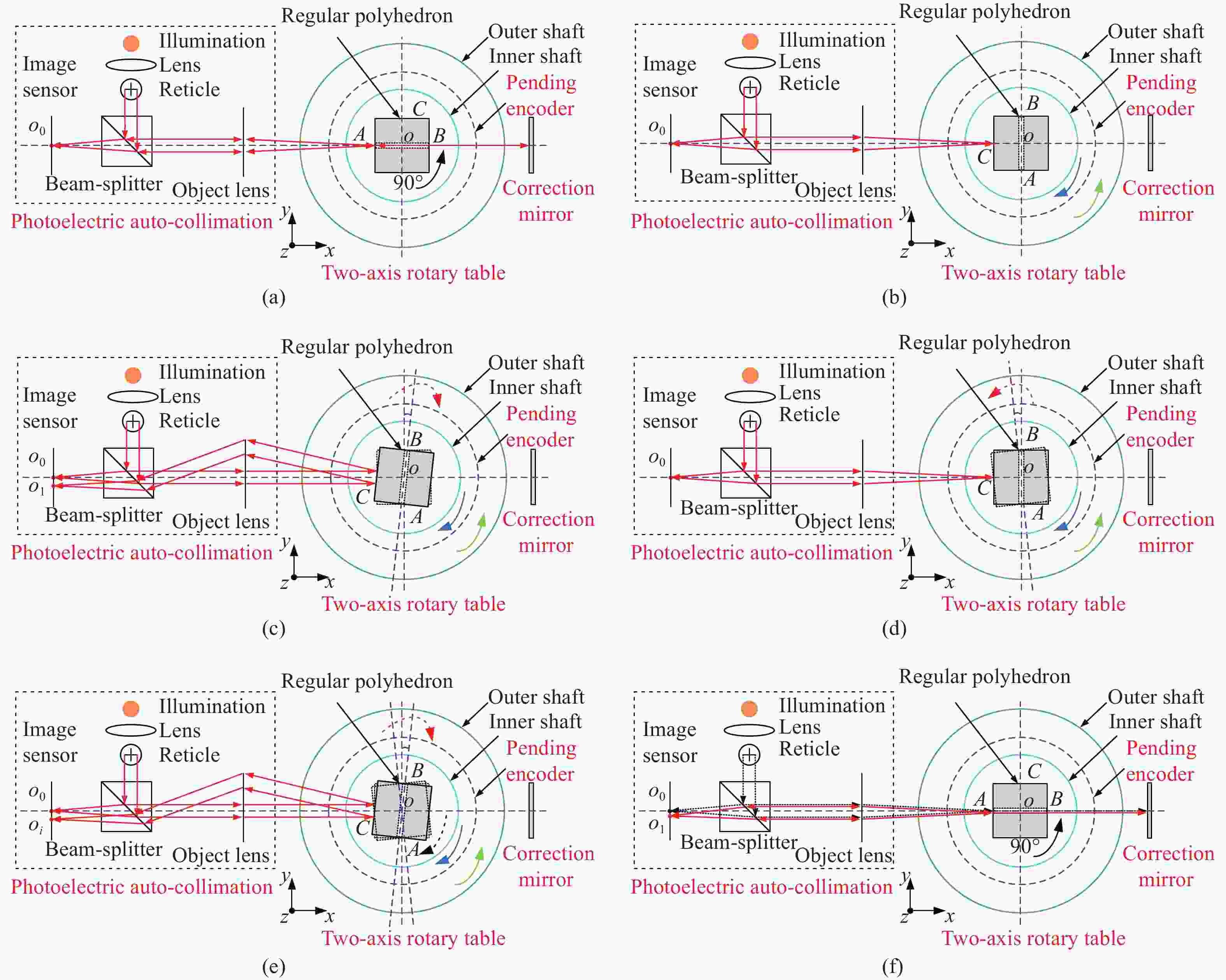
Figure 2. Detection principle of optical continuous closed-loop. (a) Self-collimation initialization; (b) System home position; (c) Corner generation and detection; (d) Reciprocal rotation; (e) Full range detection; (f) Self-collimation restoration
检测系统启动后,调整自准直仪、四面棱体(四面棱体A、B棱面具有通光孔AB)及校正反射镜位姿,自准直初始化如图2(a)所示;系统锁定双轴转台单元的内轴相对位置(内轴与外轴相对静止),外轴逆时针转动90°,调整四面棱体(四面棱体C棱面为工作棱面),工作系统回零如图2(b)所示;系统锁定双轴转台单元的外轴相对位置(外轴与基座相对静止),转动内轴,使待检编码器主轴随内轴旋转角度
$\; \beta $ 做为参考转角,且$\; \beta $ 值应不超过自准直仪量程,通过自准直检测单元的自准直仪与内轴同轴的四面棱体(工作棱面C),测得转角$ {\gamma _i} $ ,将其作为基准转角,与待检编码器输出值$ {\gamma }_{i}^{、} $ 进行差值计算,得到待检编码器位置$ i $ 的精度值:$ {\Delta }_{i}={\gamma }_{i}-{\gamma }_{i}^{、} $ ,转角产生及检测如图2(c)所示;系统解锁双轴转台单元的外轴固定关系,锁定内轴相对位置(内轴与外轴相对静止),外轴向着逆于转角产生方向转动角度$ - {\gamma _i} $ ,系统利用自准直仪与四面棱体的光学闭环(光学读数反馈),保证转轴的回转精度,转角互逆如图2(d)所示;系统解锁双轴转台单元的内轴固定关系,锁定外轴相对位置(外轴与基座相对静止),转动内轴,使待检编码器主轴随内轴旋转角度$ \;\beta $ 做为参考转角,且$ \;\beta $ 值应不超过自准直仪量程。以此类推,待检编码器输出角度值与自准直仪测量角度值独立比较后,完成待检编码器全圆周误差检测,全量程检测如图2(e)所示;经过$ n $ 个测量周期或系统需要复位检测时,系统锁定双轴转台单元的内轴相对位置(内轴与外轴相对静止),外轴顺时针转动90°,自准直光线穿过四面棱体通光孔AB,利用校正反射镜(始终保持相对静止),补偿自准直仪的漂移量,调整自准直仪复位(初始化状态),自准直复位如图2(f)所示。 -
以待检编码器与双轴转台的耦合系统作为研究对象,利用多体系统理论和相对位姿矩阵变换进行空间误差建模。在多体系统运动学上,待检组件与双轴转台属于多体串联式结构,耦合系统拓扑结构如图3所示。
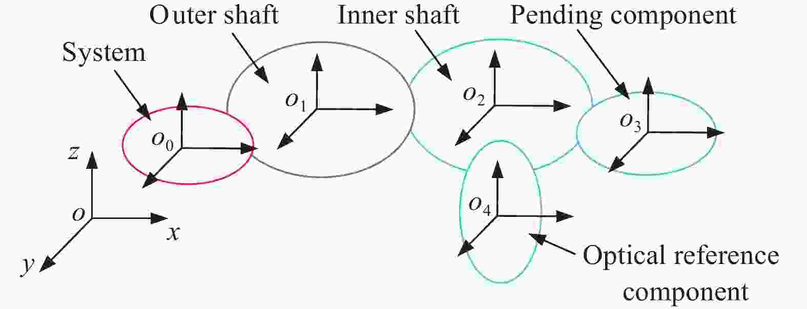
Figure 3. Topological structure of system
-
为了建立待检编码器在双轴转台上的全误差模型,以双轴转台的拓扑结构为基础,建立系统
$o$ 坐标系$ {o_0}{x_0}{y_0}{z_0} $ ,外轴$ E $ 坐标系$ {o_1}{x_1}{y_1}{z_1} $ ,内轴$ I $ 坐标系$ {o_2}{x_2}{y_2}{z_2} $ ,编码器轴$ C $ 坐标系$ {o_3}{x_3}{y_3}{z_3} $ 和光学组件轴$ S $ 坐标系$ {o_4}{x_4}{y_4}{z_4} $ 。系统坐标系$ {o_0}{x_0}{y_0}{z_0} $ 为理想参考坐标系,光学组件坐标系$ {o_4}{x_4}{y_4}{z_4} $ 为实际参考坐标系。在理想条件下,系统坐标系与内、外轴坐标系重合,光学组件主轴和编码器主轴共线。设外轴转角为$ {\alpha _i} $ ,内轴转角为$ {\beta _i} $ ,双轴系统如图4所示。
Figure 4. Schematic diagram of biaxial system
-
(1)外轴相对于系统的位姿矩阵
设外轴相对于系统的同轴度误差为
$ \Delta {\varepsilon _{x0}} $ 、$ \Delta {\varepsilon _{y0}} $ ,零位误差为$ \Delta {\varphi _{z1}} $ ,倾角回转误差为$ \Delta {\sigma _{x1}}(\alpha ) $ 、$ \Delta {\sigma _{y1}}(\alpha ) $ ,回转误差二次谐波傅里叶级数展开式为:式中:
$ \Delta {\sigma _{x1 c}} $ 、$ \Delta {\sigma _{x1 s}} $ 、$ \Delta {\sigma _{y1 c}} $ 、$ \Delta {\sigma _{y1 s}} $ 为外轴倾角回转误差的二次谐波正余弦项幅值。则,外轴相对于系统的位姿矩阵为:式中:
$ B(\nu ,\theta ) $ 为绕$ \nu $ 轴旋转角$ \theta $ 后所形成的单位位姿变换矩阵$ \nu = {x_j},{y_j},{z_j} $ 且$ j = 0,1,2,3,4 $ ;$ \varphi $ 为各个轴转角误差。因此,绕$ x $ 、$ y $ 、$ z $ 轴的单位变换矩阵为:(2)内轴相对于外轴的位姿矩阵
设内轴相对于外轴的同轴度误差为
$ \Delta {\varepsilon _{x1}} $ 、$ \Delta {\varepsilon _{y1}} $ ,零位误差为$ \Delta {\varphi _{z2}} $ ,倾角回转误差为$ \Delta {\sigma _{x2}}(\beta ) $ 、$ \Delta {\sigma _{y2}}(\beta ) $ ,回转误差二次谐波傅里叶级数展开式为:式中:
$ \Delta {\sigma _{x2 c}} $ 、$ \Delta {\sigma _{x2 s}} $ 、$ \Delta {\sigma _{y2 c}} $ 、$ \Delta {\sigma _{y2 s}} $ 为内轴倾角回转误差的二次谐波正余弦项幅值,内轴相对于外轴的位姿矩阵为:(3)光学组件相对于内轴的位姿矩阵
设内轴与光学组件之间安装误差为
$ \Delta {\tau _{x0}} $ 、$ \Delta {\tau _{y0}} $ ,光学组件相对于内轴的位姿矩阵为:(4)编码器相对于系统的位姿矩阵
设待检编码器主轴初始零位误差为
$ \Delta {\tau _{z3}} $ ,相对于转台台面的安装误差为$ \Delta {\tau _{x3}} $ 、$ \Delta {\tau _{y3}} $ ,待检编码器主轴相对于系统的位姿矩阵为: -
双轴转台采用立式内、外双转轴结构,待检编码器输入参量随机变化,以双轴转台同时、同向匀速转动后的定位精度(最复杂工况)为目标值。
待检编码器输入(系统输出)的角位置空间耦合位姿矩阵为:
式中:
$ {[1\begin{array}{*{20}{c}} {} \end{array}1\begin{array}{*{20}{c}} {} \end{array}\lambda ]^{\text{T}}} $ 为编码器角位置矩阵在主轴上产生的误差分量;$\Delta{s_x}$ 、$\Delta {s_y}$ 、$\Delta{s_o}$ 分别为编码器主轴角位置相对于$ x $ 、$ y $ 轴及系统$o$ 轴的误差分量。将各轴相对位姿矩阵与单位位姿矩阵
$ B(\nu ,\theta ) $ 分别代入空间耦合位姿矩阵。编码器主轴角位置相对$ x $ 、$ y $ 轴和系统$o$ 轴的误差分量分别为:考虑空间几何误差耦合,待检编码器输入轴全误差模型为:
式中:
${K_o}$ 为系统主轴精度系数;$ {K_x} $ 、$ {K_y} $ 、$ {K_{xy}} $ 分别为编码器主轴相对于$ x $ 、$ y $ 轴及$ x $ 、$ y $ 轴交叉耦合项精度系数;$ {K_{xx}} $ 、$ {K_{yy}} $ 为$ x $ 、$ y $ 轴二次项非线性精度系数;$ \kappa $ 为系统残差。忽略高阶小量的影响,设二次项精度系数近似误差分量为
$ \Delta {s_x}' $ 、$ \Delta {s_y}' $ 且$ \xi $ 为二次项精度调节系数,误差分量的近似取值为:待检编码器输入(系统输出)轴空间全误差方程为:
-
双轴转台系统主轴及待检编码器主轴相对
$ x $ 轴与$ y $ 轴的精度系数,影响检测系统输出角的精度,双轴转台的结构误差导致编码器输出值引入系统误差。双轴转台系统误差主要由双轴转台内、外主轴的同轴度误差、回转误差、零位误差及各个组件安装误差组成。各轴系的精度系数为固定误差影响因素;内、外主轴及编码器主轴同轴度误差$ \Delta \varepsilon $ ,倾角回转误差$ \Delta \sigma $ ,零位误差$ \Delta \varphi $ 及各个组件安装误差$ \Delta \tau $ 为可变误差影响因素。利用参考转角误差消除及全量程转角误差相互补偿后[13],待检编码器输入轴空间全误差方程为:
为了保证计算精度及优化计算过程,忽略系统误差小量影响,考虑回转误差的二次谐波,系统空间全误差方程近似为:
系统主轴的精度系数
${K_o}$ 和待检编码器主轴相对于$ x $ 、$ y $ 轴及$ x $ 、$ y $ 轴交叉耦合项精度系数$ {K_x} $ 、$ {K_y} $ 、$ {K_{xy}} $ 为固定误差影响因素且影响较小,忽略不计。通过系统空间全误差方程(15):内轴轴线相对于外轴轴线同轴度误差$ \Delta {\varepsilon _{x1}} $ 、$ \Delta {\varepsilon _{y1}} $ 和内轴倾角回转误差二次谐波项$ \Delta {\sigma _{x2 c}} $ 、$ \Delta {\sigma _{x2 s}} $ 、$ \Delta {\sigma _{y2 c}} $ 、$ \Delta {\sigma _{y2 s}} $ 是系统误差主要影响因素。双轴转台的内轴同轴度误差和倾角回转误差影响系统的空间角位置精度,将导致检测系统的输出值引入系统误差。因此,文中通过合理匹配与误差补偿的方法将四项主要几何误差控制在许用范围内,即可保证系统的检测精度。 -
以双轴转台的精度0.4″为目标值,采用MATLAB反向求解全误差方程的误差项,双轴转台各项误差最大极值见表1。
Error Max Error Max Error Max $ \Delta {\varepsilon _{x0}} $ 0.721″ $ \Delta {\varepsilon _{x1}} $ 0.825″ $ \Delta {\tau _{x0}} $ 0.025 mm $ \Delta {\varepsilon _{y0}} $ 0.952″ $ \Delta {\varepsilon _{y1}} $ 0.986″ $ \Delta {\tau _{y0}} $ 0.025 mm $ \Delta {\tau _{z1}} $ $ \infty $ $ \Delta {\tau _{z2}} $ $ \infty $ $ \Delta {\tau _{z3}} $ $ \infty $ $ \Delta {\sigma _{x1}} $ $ \infty $ $ \Delta {\sigma _{x2}} $ $ \infty $ $ \Delta {\tau _{x3}} $ 0.050 mm $ \Delta {\sigma _{y1}} $ $ \infty $ $ \Delta {\sigma _{y2}} $ $ \infty $ $ \Delta {\tau _{y3}} $ 0.050 mm Table 1. Extreme error of turntable simulation
利用各项误差极值,估计双轴回转精度为:
通过双轴转台仿真分析:内、外轴(双轴)倾角回转误差
$ \Delta {\sigma _{x1}} $ 、$ \Delta {\sigma _{y1}} $ 、$ \Delta {\sigma _{x2}} $ 、$ \Delta {\sigma _{y2}} $ 和双轴及待检编码器主轴(主轴)零位误差$ \Delta {\tau _{z1}} $ 、$ \Delta {\tau _{z2}} $ 、$ \Delta {\tau _{z3}} $ 的最大值均趋于$ \infty $ ,可知双轴及主轴倾角回转误差、零位误差对系统回转精度影响较小;内轴及主轴相对转台安装误差$ \Delta {\tau _{x0}} $ 、$ \Delta {\tau _{y0}} $ 、$ \Delta {\tau _{x3}} $ 、$ \Delta {\tau _{y3}} $ 的最大值为常数,可知双轴及主轴的安装误差不随转台角度变化而发生改变;双轴同轴度误差$ \Delta {\varepsilon _{x0}} $ 、$ \Delta {\varepsilon _{y0}} $ 、$ \Delta {\varepsilon _{x1}} $ 、$ \Delta {\varepsilon _{y1}} $ 的最大值为变量,可知双轴的同轴度误差随转台角度变化而改变。为保证双轴转台精度小于0.4″的设计要求,采用精密机械加工及装配工艺,控制安装误差位移量小于0.025 mm,通过精确控制双轴同轴度误差,保证双轴转角回转精度,实现高精度误差检测。 -
利用光学误差检测的双轴转台,建立外/内轴径向和轴向回转精度测量平台。转台内轴轴端固定测量反射镜(测量范围:0°~360°,3级)与光电自准直仪(ULTRA-3050 HR,分辨率:0.01″,精度:0.2″,2级)组成光学闭环,回转精度测量在恒温恒湿(温度(20±1) ℃,相对湿度(50±5)%)及隔振条件相对良好的实验室,测量标定点的二维角度值,转台转速10 (°)/s,采样间隔20 s,采样点数12个,正、反互逆测量取平均值,回转精度测量实验台与精度曲线如图5和图6所示。
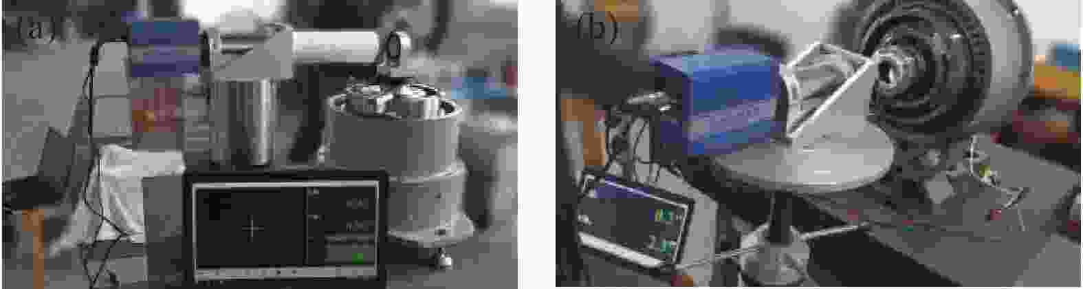
Figure 5. Measuring platform of rotation accuracy. (a) Radial direction; (b) Axial direction

Figure 6. Curve of rotation accuracy. (a) Radial direction; (b) Axial direction
由图6分析可知:测量数据具有合理的重复性,径向和轴向跳动呈周期性变化趋势,利用传统傅里叶谐波分析与经典稀疏分解拟合修正双轴误差后,径向回转精度为0.868″和1.220″,轴向回转精度为0.916″和1.275″。满足仿真计算控制双轴的回转定位精度不大于1.096″和1.371″的数值要求。
-
利用高精度光电自准直仪(测量范围:0′~10′,分辨率:0.01″,精度:0.2″,2级)与23面棱体(测量范围:0°~360°,3级)进行系统精度校准。校准实验台由控制箱、双轴转台、转台自准直仪、标定自准直仪及23面棱体组成,精度校准实验台如图7所示。
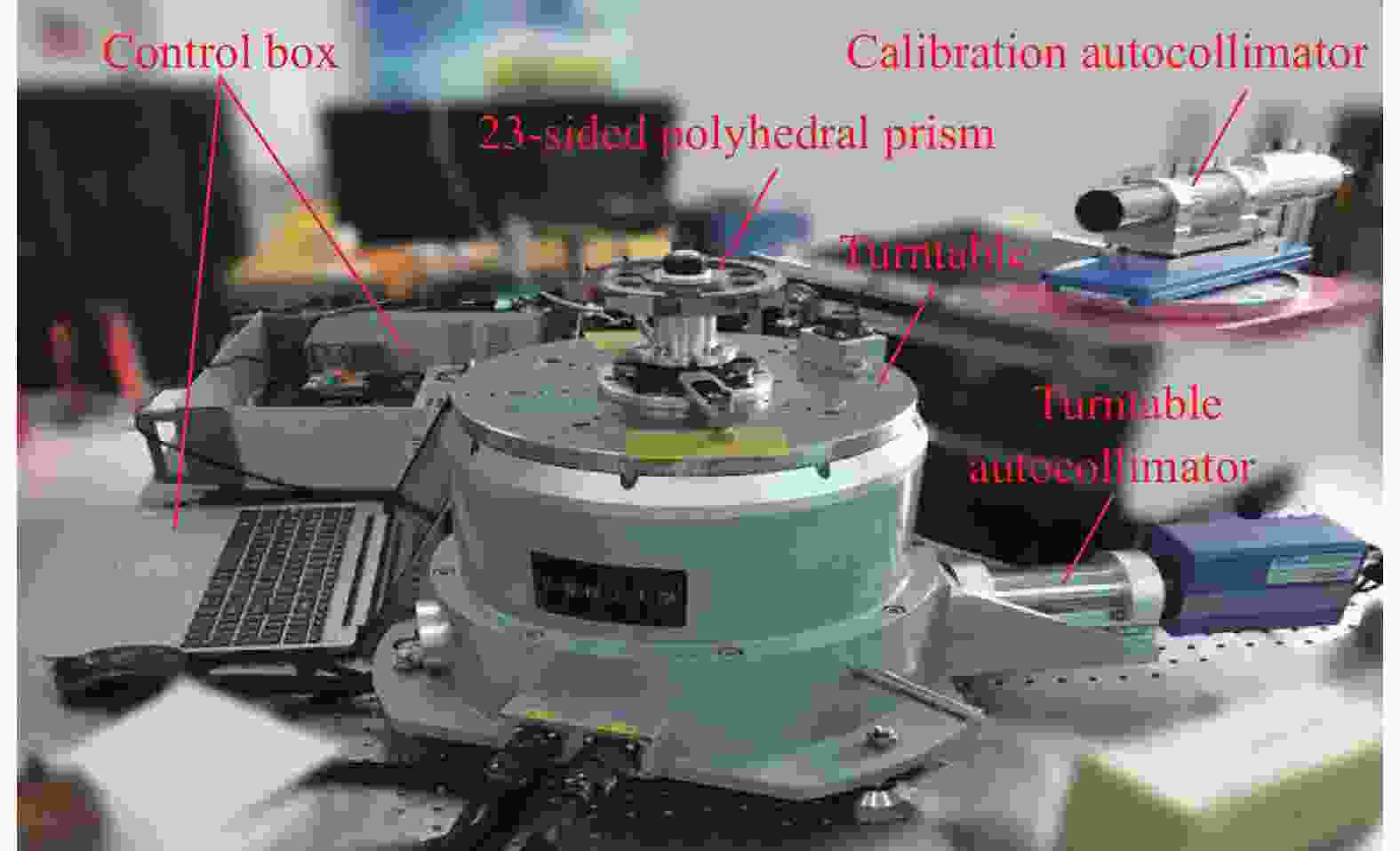
Figure 7. Experimental platform of accuracy calibration
系统校准实验对主要的影响因素进行严格控制,测试在恒温恒湿(温度20 ℃,相对湿度50%)及隔振条件相对良好的实验室进行。调整23面棱体定位夹具,使23面棱体回转中心与转台回转中心重合(控制在许用偏差0.02 mm以内),调整转台自准直仪和标定自准直仪,使自准直光束中心与对应的棱体工作面中心重合,转台转速10 (°)/s,采样间隔20 s,采样点数22个。采用全组合法与全圆周闭合原理,校准系统精度,通过精度校准曲线(图8),零起误差值0.00″,最大误差值±0.19″,系统校准后的系统精度为0.38″(峰峰值),满足亚角秒级高精度、全圆周连续误差检测要求。
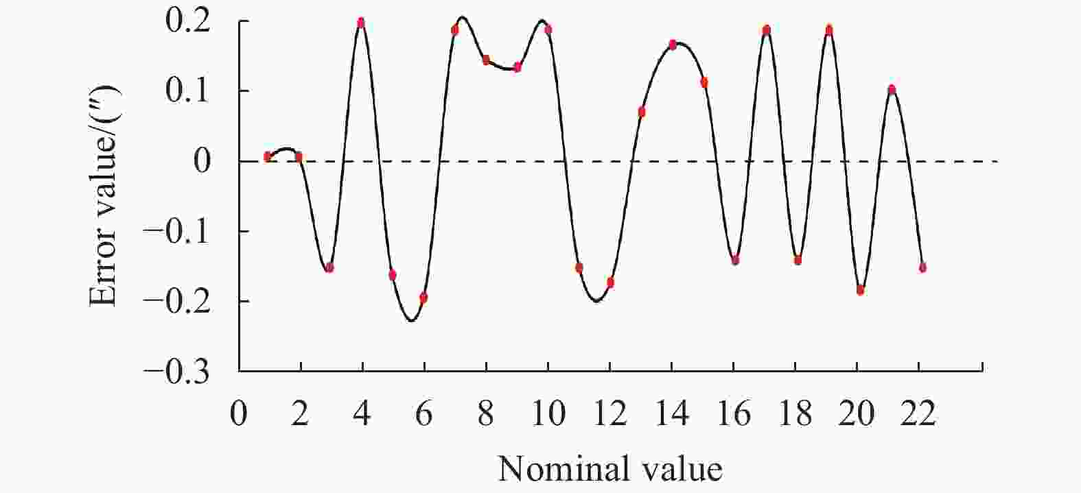
Figure 8. Curve of accuracy calibration
-
考虑不确定度的主要来源为光电自准直仪引入的不确定度分量(
$ {u_1} = 0.035'' $ )、四面棱体引入的不确定度分量($ {u_2} = 0.05'' $ )及转台的重复性引入的不确定度分量($ {u_3} = 0.072'' $ )。各不确定度分量相互独立,故灵敏度系数$ {c_i} = 1 $ ,相对自由度$ {v_i} = 50 $ 。根据不确定评定准则,计算标准不确定度分量和自由度分别为:取置信概率
$ p $ =95%,查$ t $ 分布表得到${k_{95}} = t(112) =$ $1.984$ ,取包含因子$ k = 2 $ ,扩展不确定度为: -
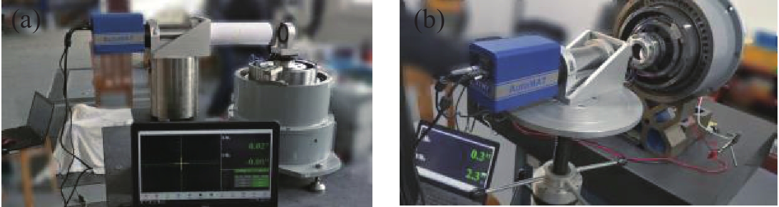
在恒温恒湿(温度19.9 ℃,相对湿度52%)及隔振条件相对良好实验室,利用长春理工大学研制的CUST-JDJCXT-001光学连续闭环光电编码器误差检测系统对长春禹衡光学生产的JZN-1高精度光电轴角编码器(分辨率:0.005″,准确度:±0.5″)进行精度对比验证。调整编码器JZN-1定位夹具,将JZN-1回转中心与转台回转中心重合,转台转速10 (°)/s,角度间隔0.25°,时间间隔20 s,采样点数1440个,精度对比实验台及系统补偿前后精度对比曲线分别如图9和图10所示。
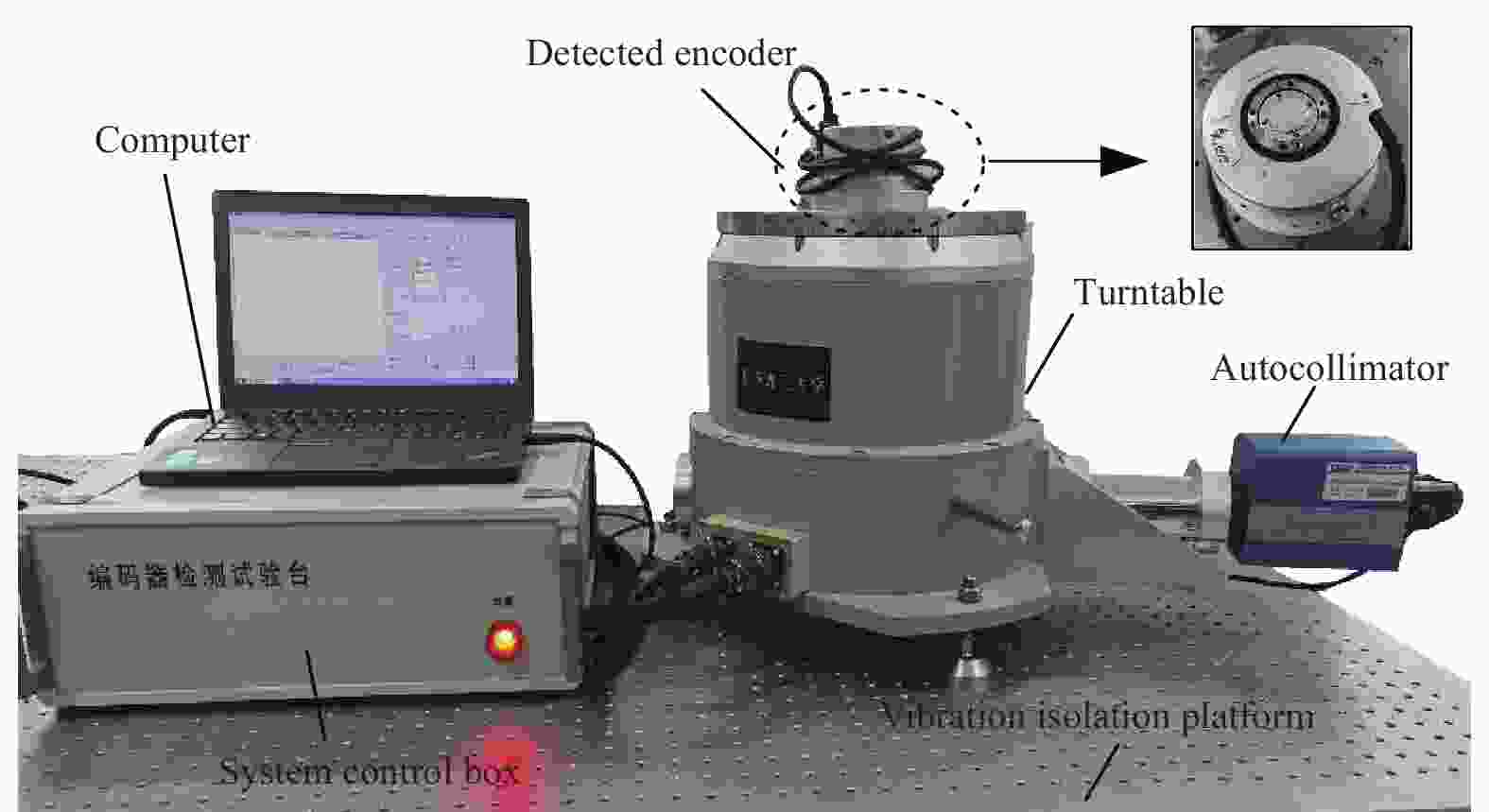
Figure 9. Experimental platform of accuracy comparison
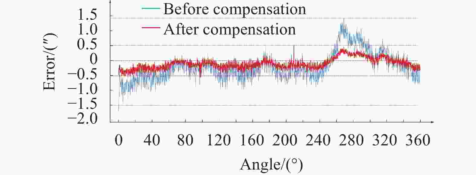
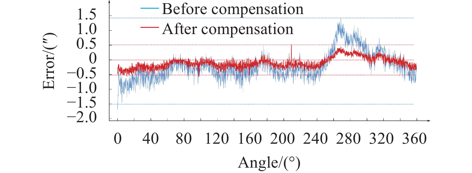
Figure 10. Comparison curves of accuracy
通过精度对比曲线可知:误差补偿后的系统检测精度与JZN-1出厂时标定准确度基本一致,但由于不同采样点,测量环境干扰和测量仪器波动等因素,某些采样点存在测量误差偏大或波动情况,但系统补偿后的总体误差分布在 ±0.5″(补偿前在 ±1.5″)以内。周期采样72个角度,实际采样时间约为15 min(标准检测方法的检测时间约为20 ~ 30 min),验证CUST-JDJCXT-001系统可以满足高精度、全量程连续误差检测的实际需求。
-
文中利用自准直仪和多面棱体的光学小角度测量原理,保证基准角度测量精度和转轴回转精度,利用转角互逆的双轴转台实现连续误差检测,建立了光学连续闭环光电编码器误差检测系统;采用多体系统理论与相对位姿矩阵变换方法,建立了双轴转台全误差模型,得到固定误差和可变误差对系统的影响规律;利用双轴转角互逆方法,消除系统零位误差与安装误差,通过双轴转台连续误差补偿,全量程补偿系统的同轴度误差与倾角回转误差,保证双轴的回转精度满足数值仿真的定位精度要求。实验表明,光学连续闭环误差检测系统精度可达0.38",测量不确定度为0.2"(k=2),满足亚角秒级全量程连续误差检测的需求,对生产制造光电编码器产品,实现全周期连续误差标定具有一定的应用价值。
Error detection system of photoelectric encoder based on optical continuous closed-loop
doi: 10.3788/IRLA20210715
- Received Date: 2022-01-20
- Rev Recd Date: 2022-02-25
- Publish Date: 2022-08-05
Fund Project:
National Key Research and Development Program of China(2017 YFF0105304);Science and Technology Development Plan Project of Jilin Province(20200401117 GX);Youth Fund project of Changchun Institute of Technology(320210006)
-
Key words:
- photoelectric encoder /
- error measurement /
- photoelectric autocollimator /
- error modeling /
- turntable
Abstract: In order to solve the problems of low accuracy, complex optical machine structure, and long detection cycle in the error detection of the photoelectric encoder, the optical small-angle measurement principle of an autocollimator and a polyhedral prism, and the continuous error detection method of the reciprocal rotation angle of the dual-axis turntable were combined to establish an error detection system for photoelectric encoder based on optical continuous closed-loop. By using the multi-body system theory and the relative pose matrix transformation method, a full error model of the dual-axis turntable was established, and the influence of the fixed error and variable error of the full error model on the system was analyzed. The detection system was calibrated with a calibrated autocollimator and a 23-sided polyhedral prism, and a high-precision photoelectric encoder was used to compare the detection accuracy with the system. The test results show that the rotation accuracy of the dual-axis had met the requirements of the numerical simulation calculations, the system detection accuracy had reached 0.38″, and the measurement uncertainty is 0.2″ (k=2). And for the encoder actually produced, the detection accuracy of the system is basically the same as the accuracy of the factory calibration. Which had been verified the feasibility of the optical continuous closed-loop system to achieve high precision and circumference continuous error detection.


 DownLoad: