


-
星敏感器是卫星姿态测量的重要部件,对于光学成像卫星,为了能控制卫星姿态,对遥感图像进行精确定位,需保证星敏感器与卫星载荷航天相机之间严格的姿态关系[1-3]。针对星敏感器与相机的高精确配准,一些学者进行了设计及检测方法的研究,从而提高星敏感器的指向精度或保证其精度稳定性,孙刚等人建立了一种高精度的星敏感器与卫星相机的姿态关系自动化测量系统,最终可实现5″的系统姿态测量精度,并将其用于高分二号的相机与星敏感器的姿态关系测量[4]。余成武等人针对高分七号卫星甚高精度星敏感器的高热稳定性任务需求,进行了星敏感器的结构和热设计,将星敏感器的光轴指向性误差保证在0.3 (″)/℃以内[5]。魏新国等人通过星敏感器主光轴和遥感相机主光轴交联角的在轨检校方法,进行了星敏感器和遥感相机姿态关系的系统误差补偿,最终使得遥感图像的定位精度得到显著提高[6]。星敏感器支架作为星敏感器和相机集成的重要载体,是实现星敏感器和相机高精度姿态关系的关键部件。目前,较多研究都是针对星敏感器支架的结构和热稳定性进行了星敏感器支架的优化设计[7],但对于星敏感器支架与相机间固有的姿态关系精度,一般仅是通过高精度数控机床进行超精密加工来保证,田丽丽针对高精度星敏感器支架的加工,进行了机床制造误差、径向跳动误差、刀具稳定误差分析,并采用动态测量方法进行了加工误差补偿,但由于多种原因依然不能普适性地对各种材料、各种结构的星敏感器支架进行误差模型应用[8]。星敏感器支架的姿态精度主要体现为单方向的指向精度,因此如何有效地对星敏感器支架的指向性进行标定及误差校正是提高星敏感器与相机配准精度的重要课题[9-11]。
-
星敏感器支架的指向性标定及校正即是实现星敏感器支架在相机机身上的精密装调。常规的技术方法中,对有严格姿态要求的两个部件进行精密装调时,需先通过研磨保证两对接面的平面度,然后通过经纬仪、干涉仪等光学测量方法对其实际姿态进行检测,再根据测量结果,进行对接面的研磨修正,这样反复迭代,最终可实现角秒级的装调精度。在整个过程中,最重要的步骤是如何确定两精密部件的姿态偏差量和通过检测结果进行修研量及修研方向的计算和判断。对于两个姿态关系简单的零部件,方法比较容易,姿态偏差量可以通过经纬仪正交的高低角和方位角单独计算,修研量通过将角度误差转化为线位移量获得。
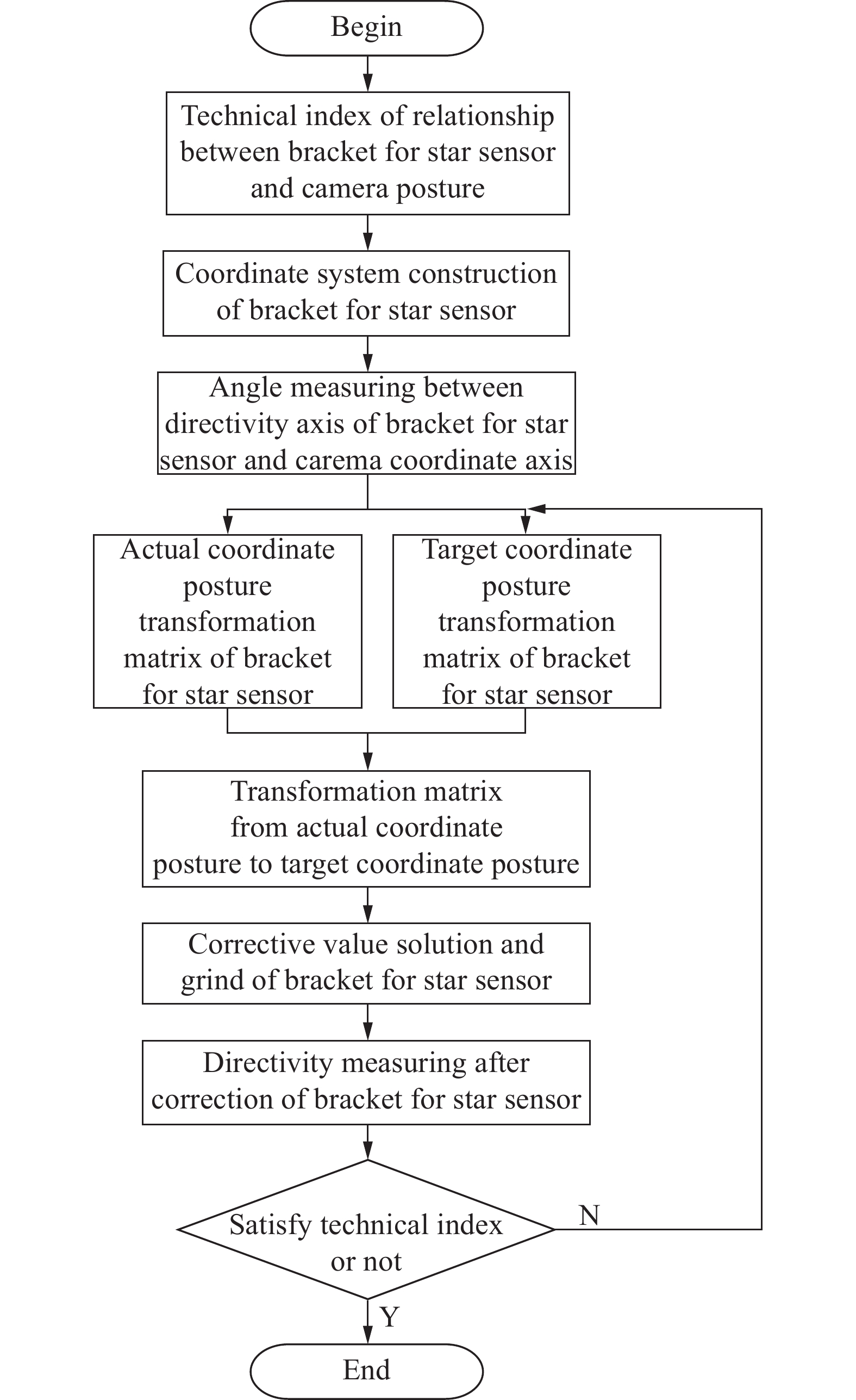
根据上述原理及星敏感器支架的单方向指向性特点[12],决定通过交互测量、姿态变换、定量修研的技术途径,实现星敏感器支架与相机机身的高精度配准关系。星敏感器支架具有两个高精度的研磨对接面,一个是与航天相机固连的对接面,另一个是与星敏感器连接的对接面。为保证更高效地校正星敏感器的指向轴,选择星敏感器支架的星敏感器对接面作为修研校正面。具体装调策略为:首先将星敏感器支架与相机固定连接,根据星敏感器支架的星敏感器连接面建立星敏感器坐标系,然后对星敏感器坐标系与航天相机坐标系各坐标轴夹角关系进行测量,并根据测量结果计算实际星敏感器坐标系与航天相机坐标系的姿态变换矩阵T1,再根据理论的星敏感器坐标系与航天相机坐标系各坐标轴夹角关系,计算理论星敏感器坐标系与航天相机坐标系的姿态变换矩阵T2,根据姿态变换矩阵T1、T2计算星敏感器实际坐标系到理论坐标系的变换矩阵T3。根据T3确定星敏感器实际坐标到理论坐标变换的RPY角,根据该角度确定星敏感器支架的星敏感器对接面的测量点的修调量。根据该计算值进行定量修研,然后对星敏感器指向轴与航天相机坐标轴夹角关系进行修调后复测,若不满足指标要求,可重复上述步骤进行多次迭代,其详细的精密装调流程图如图1所示。

Figure 1. Flow chart of precise assembly and adjustment of star sensor bracket
-
星敏感器支架的指向轴与航天相机坐标轴夹角关系可以通过两台经纬仪交互测量的方式获得。首先通过虚拟坐标轴的方法进行星敏感器支架坐标系的建立。如图2所示,以星敏感器支架的星敏感器对接面的法向向量作为星敏感器支架的q轴,然后构建虚拟水平轴,即以水平面内与q轴垂直的水平轴作为星敏感器支架的m轴,根据右手定则确定星敏感器支架的n轴,为求解星敏感器支架坐标系与相机坐标系的姿态变换关系,规定星敏感器支架的m、n、q分别对应航天相机的x、y、z轴。测量时可先将相机的xy轴调水平,再用平晶贴靠星敏感器支架的星敏感器对接面,分别用经纬仪1和经纬仪2准直平晶和相机的X轴,测得经纬仪1的高低角为Vq,将经纬仪1和经纬仪2互瞄,测得经纬仪1和经纬仪2的方位变化角分别为Hqx和Hxq,如图3所示,根据三余弦定理确定星敏感器支架q轴与x轴夹角为:

Figure 2. Modeling of star sensor support coordinate system
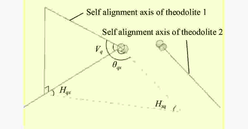
Figure 3. Model of interactive measurement
同理根据该方法可以获得q轴与y轴夹角为:
式中:Hqy与Hyq为准直平晶的经纬仪1和准直相机坐标系y轴的经纬仪2互瞄时的方位变化角。根据θqx和θqy可以获得星敏感器支架q轴与相机坐标系z轴的夹角为: 公式中的正负取决于Vq的大小,若Vq>90°,公式符号为正,若Vq<90°,公式符号为负,因此可获得星敏感器支架指向轴与相机xyz轴的夹角关系。根据该实际测量值可进行任务指标的对比,判断星敏感器支架的装调精度是否合格。
-
为获得星敏感器支架实际状态与理想状态的偏差量,需要求解星敏感器支架实际坐标系到理论坐标系的姿态变换矩阵。由于星敏感器支架的理论坐标系无法直接测量,但可根据星敏感器支架指向轴与相机坐标轴的理论夹角关系进行星敏感器支架理论坐标系与相机坐标系的姿态变换矩阵求解,然后采用相机坐标系进行中间传递的方法,获取星敏感器支架实际坐标系到理论坐标系的变换矩阵。详细方法及步骤如下:根据上述的检测方法已获得qx、qy、qz的夹角具体值,由于星敏感器支架实际坐标系的m轴为水平轴,同时相机检测前已将XY轴调为水平状态,因此可确定mZ轴的夹角为90°,此时qz、mz均为已知量,因此可根据公式(4)求nz大小:
式中:±号根据nz轴夹角大小确定,若大于90°,符号为负;若小于90°,符号为正。
星敏感器支架实际坐标轴与相机坐标轴的对应关系及当前已明确状态如图4所示。红色线连接的两轴夹角关系为第一级求解结果,黄色线连接的两轴夹角关系为第二级求解结果,该值可通过第一级结果进行求解,具体方法为:
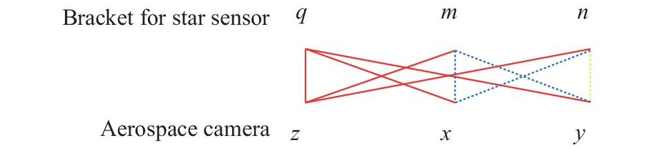
Figure 4. Corresponding relationship of coordinate axis and solution state
剩下的蓝色连线为第三级求解结果,由于同一坐标系具有任意两轴互相垂直特点,因此空间任一方向向量与坐标轴xyz的夹角α、β、γ满足公式(6)的等式关系。根据该等式关系及第一级和第二级求解结果,可以很容易的求解第三级坐标轴夹角具体值。
根据星敏感器支架实际坐标轴与相机坐标轴夹角关系可以进行姿态变化RPY角(横滚、俯仰、偏转)的求解,即以相机坐标系o-xyz为固定坐标系,星敏感器支架实际姿态的坐标系O’-mnq相对于相机的变换角度。具体的变换顺序为:先绕x轴转
${\theta _x}$ ,再绕y轴转${\theta _y}$ ,最后绕z轴转${\theta _z}$ ,各变换角度的具体求解方法如公式(7)~(9)所示:式中:
$ {r_{11}} = \cos (mx) $ ,$ mx $ 为星敏感器支架实际姿态的m轴与相机x轴的夹角;$ {r_{21}} = \cos (my) $ ,$ my $ 为星敏感器支架实际姿态的m轴与相机y轴的夹角;$ {r_{31}} = \cos (mz) $ ,$ mz$ 为星敏感器支架实际姿态的m轴与相机z轴的夹角;$ {r_{32}} = \cos (nz) $ ,$ nz$ 为星敏感器支架实际姿态的n轴与相机z轴的夹角;$ {r_{33}} = \cos (qz) $ ,$ qz $ 为星敏感器支架实际姿态的q轴与相机z轴的夹角;$ A\tan 2(y,x) $ 为“四象限反正切函数”,具体表达式为:根据上述RPY角可以获得相机坐标系到星敏感器支架实际坐标系的变换矩阵T1表示为[13]:
同时具有如下等式关系:
式中:
$ A = {[\begin{array}{*{20}{c}} {{A_x}}&{{A_y}}&{{A_z}} \end{array}]^{\rm{T}}} $ ;$ a = {[\begin{array}{*{20}{c}} {{a_m}}&{{a_n}}&{{a_q}} \end{array}]^{\rm{T}}} $ ;a为星敏感器支架实际坐标系内任意一点的坐标;A为转变到相机坐标系中的坐标。同理可知星敏感器支架理论坐标系到相机坐标系的变换矩阵为T2,并具有公式(13)、(14)的等式关系:式中:b为星敏感器支架理论坐标系中任意一点的坐标;B为该点转换到相机坐标系中的坐标;
${\theta _x}'$ 、${\theta _y}'$ 、${\theta _z}'$ 为相机坐标系到星敏感器支架理论姿态坐标系变换的RPY角。其具体值可参照公式(7)~(9)进行求解。根据公式(12)可知若将相机中任意一点变换到星敏感器支架实际坐标系中,其具体变换方法为:
若将星敏感器支架理论姿态坐标系中坐标为c的一点转换到星敏感器支架实际姿态坐标系中,需要先将其转换到相机坐标系,然后再转换至星敏感器支架实际姿态坐标系中,转换公式可表示为:
根据公式(16)可以确定星敏感器支架实际姿态到理论姿态的转换矩阵T3,可表示为:
根据该转换矩阵可以求出星敏感器支架实际姿态变换到理论姿态的RPY角,即以当前星敏感器支架坐标系为初始点,按一定顺序绕m、n、q轴转动
$ {\theta _m} $ 、$ {\theta _n} $ 、$ {\theta _q} $ 可获得理论的星敏感器支架姿态。 -
根据星敏感器支架实际姿态到目标姿态的RPY角,可进行星敏感器支架与星敏感器连接面修调量的求解,如图5所示B1、B2、B3、B4是星敏感器支架安装面上4个修研测点,将已建立的星敏感器支架坐标系O-mnq坐标原点O移至B1。根据星敏感器支架结构尺寸确定B1、B2、B3、B4的坐标分别是(0,0)、(xB2,yB2)、(xB3,yB3)、(xB4,yB4) 。星敏感器支架实际坐标到理论坐标的变换角度为θm、θn、θq,其中θq转角不影响星敏感器的指向性,因此不进行该角度的变换,最终计算各点的修调量如公式(18)~(21)所示:
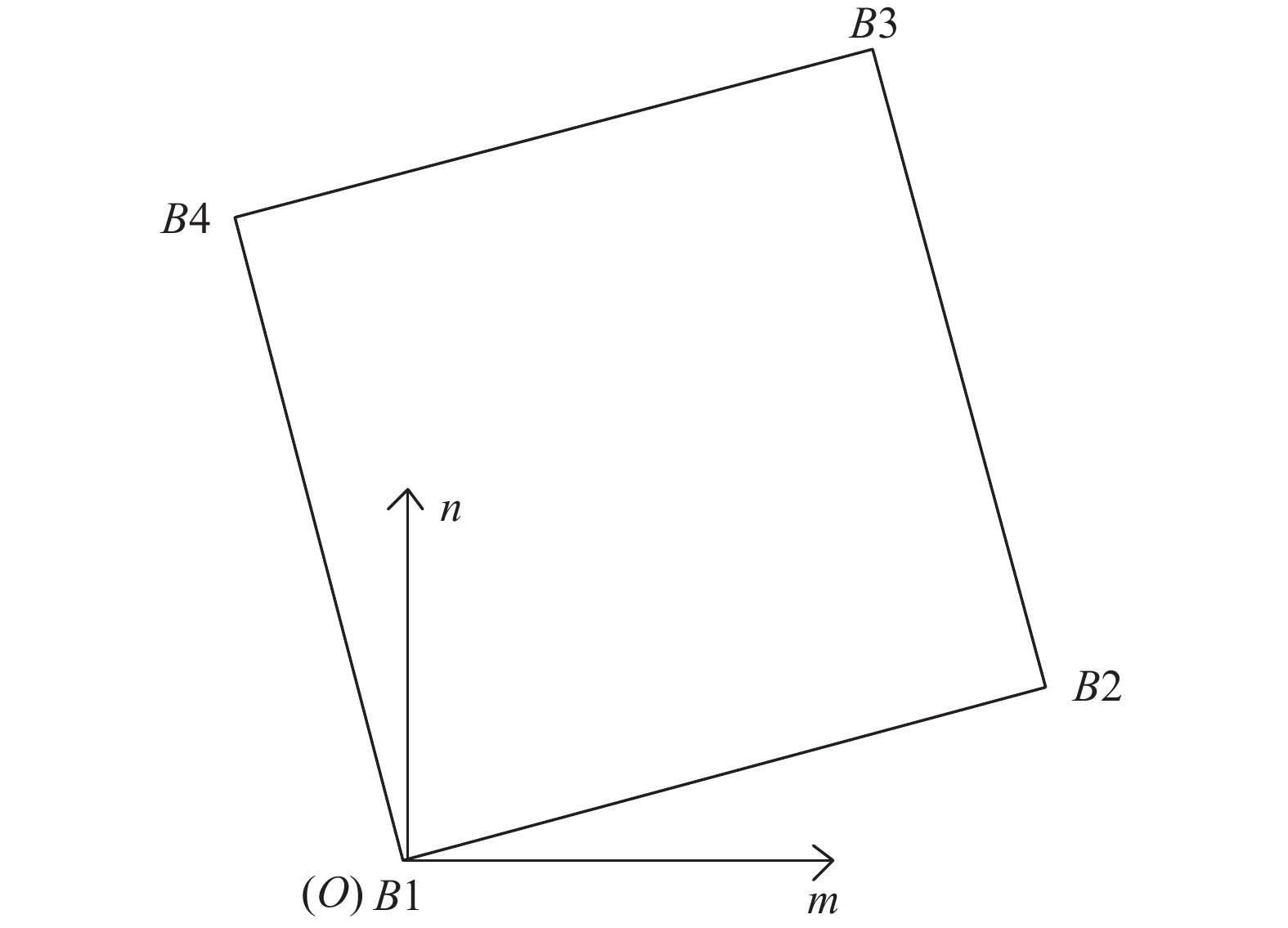
Figure 5. Schematic diagram of measuring point coordinates
修调时只能对各测点研磨去量,因此若求解的测点修调量值为负数,需将负值点找正。对最大负值测点进行归零, 然后将其余测点平移校正。上述求解量中若
$ {x_{B3}} \cdot {\theta _n} \gt {y_{B3}} \cdot {\theta _m} $ ,则需对B3测点修调量归零,最终得到的其余各测点的修调量为:根据该修调量可通过直接修研连接面或增加修研垫的方法对星敏感器支架的实际指向误差进行修正。
-
根据上述星敏感器支架的指向性标定及校正理论,对某相机的星敏感器支架装调进行了试验研究。根据卫星总体技术要求,星敏感器支架的指向轴q要求与相机的坐标轴xyz的夹角分别为37.2491°、76.8521°、55.8810°,指向精度要求优于30”。星敏感器支架与相机坐标的位姿关系如图6所示。对相机和星敏感器支架对接面的平面度进行修研保证平面度优于0.005 mm后,将星敏感器支架安装在相机本体上,将相机x、z轴通过经纬仪监测调至与大地水平面平行,用平晶贴靠星敏感器支架与星敏感器的连接面,通过两台经纬仪交互测量获得星敏感器支架实际坐标与相机坐标关系,为保证测量数据的精确,对qx和qz重复测量三次取平均值,然后利用该结果进行其余坐标轴夹角关系求解,qx和qz的三次测量结果如表1所示。再根据总体对星敏感器支架的指向性技术要求,求解星敏感器支架理论坐标与相机坐标的关系,理论和实际数据对比如表2所示。
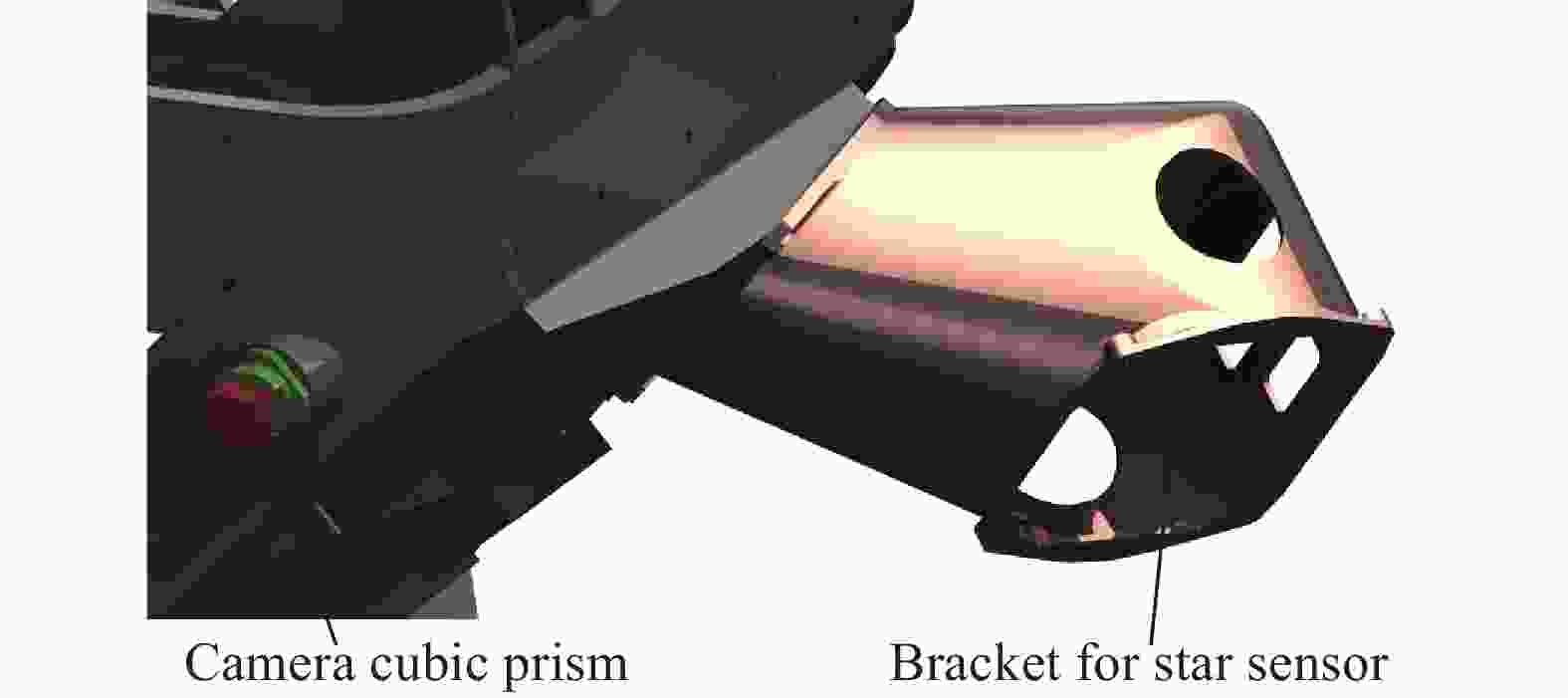
Figure 6. Position relationship between star sensor bracket and camera’s cube prism
First Second/(°) Third/(°) Average/(°) qx 37.4154 37.4162 37.4161 37.4159 qz 55.665 55.6650 55.6646 55.6649 Table 1. Measurement results of qx and qz
根据星敏感器支架坐标与相机坐标实际和理论关系的对比可知:星敏感器支架安装后其指向轴的指向误差分别为:∆qx=0.1668°, ∆qy=0.0909°, ∆qz=−0.2126°。根据星敏感器支架实际姿态坐标系与相机坐标系的坐标轴夹角关系求解实际姿态的RPY角,得
${\theta _x}$ =−13.0570°,${\theta _y}$ =54.6196°,${\theta _z}$ =0。再根据星敏感器支架理论姿态坐标系与相机坐标系的坐标轴夹角关系求解理论姿态的RPY角,得${\theta _x}'$ =−13.1479,${\theta _y}'$ =54.8294,${\theta _z}'$ =0。根据上述角度可求星敏感器支架实际坐标系到理论坐标系的姿态变换矩阵为:Camera coordinate system x/(°) z/(°) y/(°) Coordinate system of
bracket for star sensorTheory q 37.2491 55.8810 76.8521 m 54.8294 144.8294 90 n 100.7159 97.5287 13.1479 Reality q 37.4159 55.6649 76.9430 m 54.6196 144.6169 90 n 100.6145 97.5163 13.057 Table 2. Relationship comparison between actual coordinate, theoretical coordinate of bracket for star sensor and camera coordinate
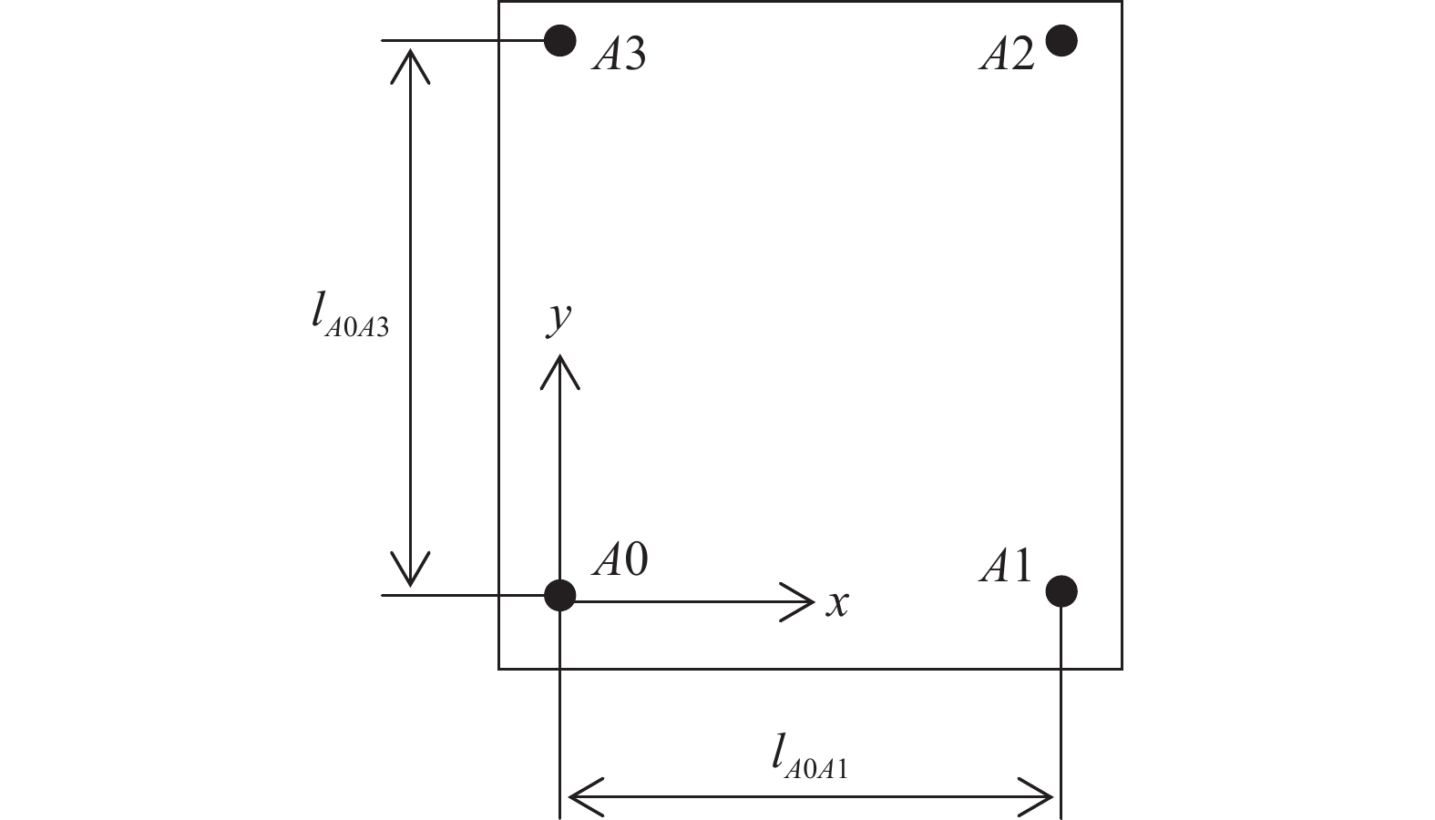
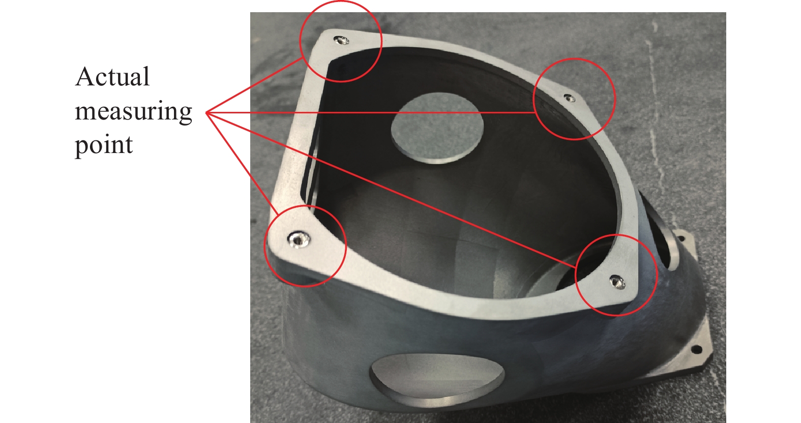
根据该矩阵可求星敏感器支架实际坐标系到理论坐标系的RPY角。得Rx=−0.0917°, Ry=0.2063°, Rz= 0.0458°。由于Rz不影响星敏感器支架指向轴与相机坐标系的姿态关系,因此不对该偏差量进行修调。对星敏感器支架与星敏感器对接面修研前,需先确定4个检测位置点,然后计算4个检测点的修研量。为了方便计算,测点按坐标方向取规则矩形的4个角点,同时将星敏感器支架实际坐标系的原点设置在其中一个测点上。对接面的结构尺寸如图7所示,其中lA0A1=173 mm,lA0A3=188 mm。实际测点位置如图8所示,4个测点全部设置在星敏感器的连接螺纹孔附近。

Figure 7. Schematic diagram of docking surface
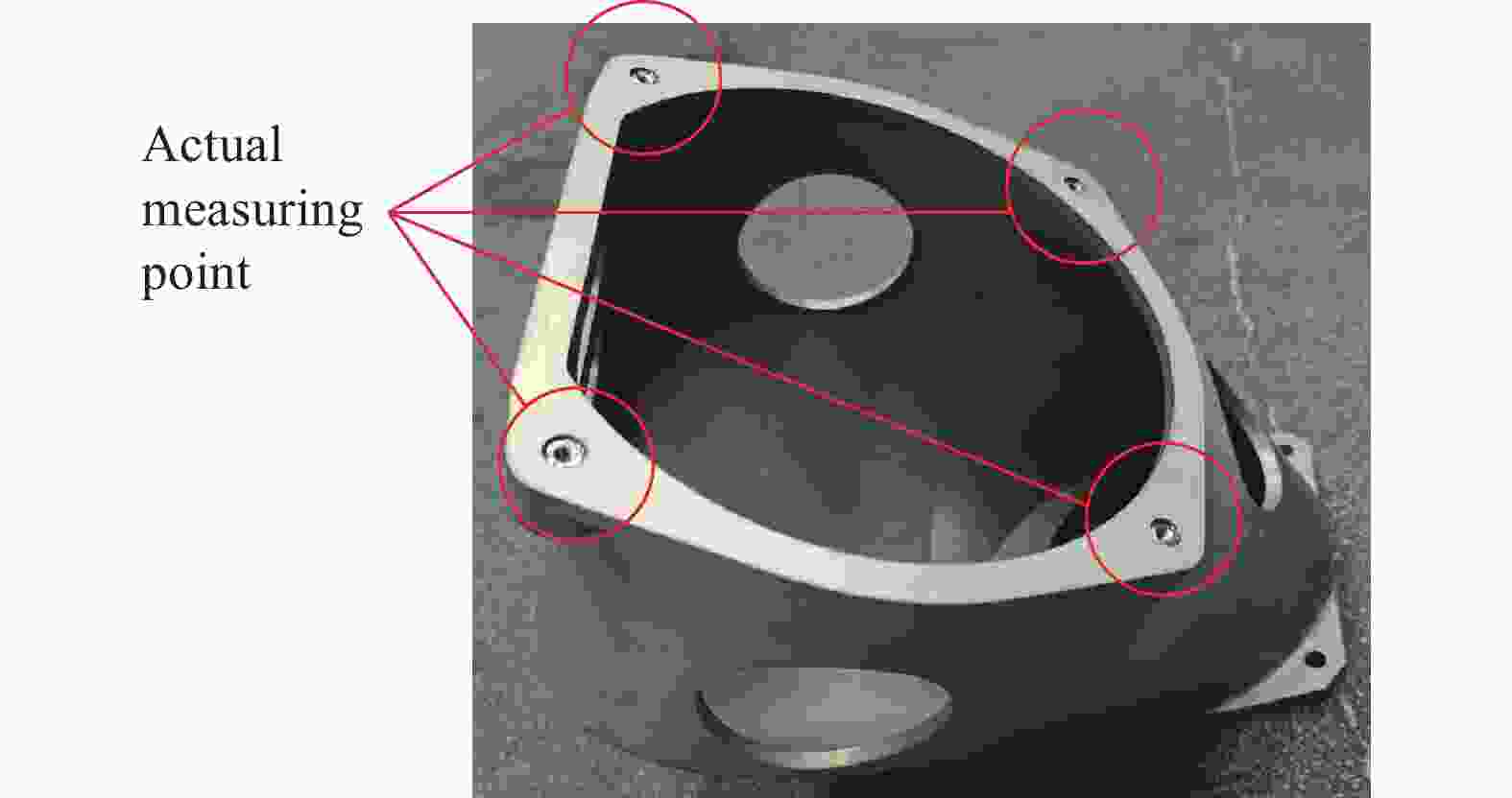
Figure 8. Actual measuring points of star sensor bracket
根据测量点的位置关系及姿态变换角度,求得各测量点修调量,然后将修调量最大负值点归零。可得各点的修调量可表示为:
按上述求解量进行去量修研,同时需保证修调后平面度优于0.005 mm。修调完对星敏感器支架重新安装后进行姿态复测,测量步骤同第一次测量,对qx、qz测量三次取平均值求解,测量结果如表3所示,最终坐标关系计算结果如表4所示。
First/(°) Second/(°) Third/(°) Average/(°) qx 37.2403 37.2405 37.2416 37.2408 qz 55.8860 55.8850 55.8855 55.8855 Table 3. Measurement results of qx and qz after the first grinding and calibration
Camera coordinate system x/(°) z/(°) y/(°) Coordinate system of
bracket for star sensorq 37.2408 55.8855 76.8606 m 54.8355 144.8355 90 n 100.7098 97.5228 13.1394 Table 4. Retest result after the first grinding and calibration
根据测量结果,可求星敏感器支架在第一次修研后指向轴的指向误差分别为:∆qx=−0.0082°,∆qy=0.0085°,∆qz=0.0045°。相比于修调前其指向精度明显提高。然后按照第一次计算步骤进行第二次修调量的计算,并进行第二次修研。第二次修调去量的结果为:δA0=0.019 mm,δA1=0,δA2=0.019 mm,δA3=0.038 mm。修研结束后,进行星敏感器支架指向轴精度复测,结果如表5所示。
Camera coordinate system x/(°) z/(°) y/(°) Coordinate system of
bracket for star sensorq First 37.2489 55.8806 - Second 37.2482 55.8804 - Third 37.2481 55.8804 - Average 37.2484 55.8805 76.8545 Table 5. Retest result after the second grinding and calibration
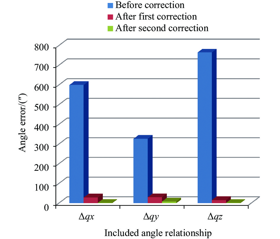
从结果可计算,第二次修调后星敏感器支架指向轴精度∆qx=−2.52″,∆qy=8.64″,∆qz=−1.8″。该精度满足指标要求,因此完成对星敏感器支架的精密装调。在星感器支架的指向性标定及校正过程中,经纬仪的测试误差为2″,平晶的平行度误差约为2″,研磨修正的误差可控制在1″以内,因此受上述因素限制最终星敏感器支架的指向性精度最高可达到5″量级。对于上述修正结果,基本已接近极限精度。将修正前和两次修正后的星敏感器支架指向精度列于表6中,将偏差量取绝对值后用柱形图表示,如图9所示。
Situation Included angle relationship ∆qx/(″) ∆qy/(″) ∆qz/(″) Before correction 600.48 327.24 −765.36 After first correction −29.52 30.6 16.2 After second correction −2.52 8.64 −1.8 Table 6. Comparison of deviation before and after calibration of star senstor support

Figure 9. Pointing accuracy histogram of star senstor bracket before and after correction
-
由于星敏感器支架指向轴与相机坐标系具有极其自由的空间夹角关系,同时星敏感器又具有严格的指向性要求,因此实现星敏感器支架的超精密装调是提高卫星对图像定位精度的重要解决方案。文中通过交互测量、姿态变换、定量求解及修研的策略提供了一种高效、高精度的星敏感器支架标定及校正方法。并对某相机进行了星敏感器支架装调试验研究,通过两轮的迭代修研,使最初的760″的装调精度修正到10″以内,表明该方法的有效性及实用性。该方法同样可指导其它有空间姿态关系的精密零部件的装调。
Directivity calibration and correction of bracket for star sensor
doi: 10.3788/IRLA20210875
- Received Date: 2022-02-10
- Rev Recd Date: 2022-03-25
- Publish Date: 2022-09-28
Fund Project:
Large Aperture Optical Foundation of ChangChun Institute of Optics,Fine Mechanics and Physics,Chinese Academy of Sciences(Y6A912U160)
-
Key words:
- star sensor bracket /
- pointing accuracy /
- interactive measurement /
- posture transformation
Abstract: In order to ensure the high-precision pointing of bracket for star sensor after installation, a technical method for quantitative grind of bracket for star sensor was proposed. Firstly, we established the star sensor bracket’s coordinate system by constructing the virtual horizontal axis, then obtained the angle relationship between any two coordinate axes by the theodolite interactive measurement and sequential solving strategy. According to the results, we got the posture transformation matrix between star sensor bracket’s actual coordinate system and the space camera’s coordinate system. By the technical requirements of the star sensor bracket’s installing, we acquired the posture transformation matrix between the ideal star sensor bracket’s coordinate system and the space camera’s coordinate system. Then, we obtained the posture transformation matrix from the actual coordinate system to the ideal coordinate system by bridge of the camera coordinate system. According to this result, the corrective value of bracket for star sensor was accurately solved. The experimental research shows that this method can improve the star sensor bracket’s pointing accuracy from the initial 760″ to less than 10″ after two rounds of iteration, which proves effectiveness of the method. At the same time, directivity calibration and correction of bracket for star sensor can also guide the precise assembly and adjustment of other two components with spatial free angle relationship.


 DownLoad: