


-
惯导系统因其自主性高、抗干扰能力强并且可以提供丰富的导航参数而被广泛应用于航空、航天、航海和陆用车辆等领域[1]。而其作为保障武器精确打击的核心导航系统的必要前提是可以保证高可靠性和高精度。提高惯导系统的可靠性可以通过冗余配置惯性器件来实现,这种由惯性器件冗余配置而组成的器件级冗余惯导系统已经成为了研究热点[2]。器件级的冗余惯导系统相对于传统的三轴正交配置的惯导系统可以大幅提高系统的可靠性,而其相比于系统级的冗余惯导系统又能在保证可靠性相当的情况下降低成本、减小体积和质量[3]。为了在实现系统高可靠性的同时实现高精度,旋转调制技术可以在惯性器件精度不变的情况下,通过将IMU绕单轴或多轴有规律的旋转将惯性器件的误差调制成周期性地变化信号使其相消,从而达到降低系统导航误差累积的目的[4]。
初始对准是惯导系统开始导航的必要前提,其作用是确定载体在初始时刻的姿态和航向,从而建立载体坐标系到导航坐标系(地理坐标系)之间的方向余弦阵,初始对准的精度直接影响导航精度。目前,传统的捷联惯导系统初始对准技术已经较为成熟,但是其在静基座下初始对准的可观测性较差,这直接影响了初始对准的快速性和精度[5]。1992年,Meskin[6]等提出可在一定条件下通过基座的有目的机动提高系统的可观测性。1993年,Lee[7]等在此基础上首次提出了多位置初始对准方法,并实现了提高捷联惯导系统对准精度的最优二位置对准,获得了较好的效果,随后引发了多位置初始对准的研究热潮。多位置对准技术也可以应用于解析对准,但其只能使用转停状态下的惯性器件输出的数据。谭彩铭[8]等提出了最简多位置解析对准方法,通过几何方法得到IMU偏置的几何解,但是计算方法比较复杂,计算结果受先验信息的影响也比较大。丁磊香[9]等在最简多位置解析对准方法基础上进行了改进,推导了IMU偏置的解析表达式,得到了任意多位置IMU偏置的解析解,解析方法计算简单,解决了先前解析式对准方法存在的受先验信息影响较大的问题。
上述关于捷联惯导系统的初始对准方面的研究已经较为成熟,而目前并未查阅到有关冗余旋转惯导系统(Redundant Rotating Inertial Navigation System, RRINS)初始对准方面的研究。文中以正四面体冗余旋转惯导系统为例,首先推导了在惯性器件(3个陀螺仪和3个加速度计)组合方式下惯性器件的零偏与冗余配置相关的解析表达式,然后利用两位置的测量信息可以求得每个惯性器件的零偏,最后将求得的零偏对惯性器件的测量信息进行补偿后做对准和导航。在理论分析的基础上做了数学仿真和实验,验证了该方法可有效提高RRINS的初始对准精度。
-
以正四面体冗余旋转惯导系统为例进行研究,图1所示为正四面体RRINS的IMU的三维模型图和冗余配置三维示意图。

Figure 1. Redundant configuration of IMU
图1中,正四面体配置的冗余IMU安装框架是正四面体结构,底面是正三角形,3个侧面安装面均是等腰三角形,侧面和底面的夹角均为
$ \alpha {\text{ = }}70.53^\circ $ 。s1代表陀螺仪1和加速度计1,s2、s3、s4分别代表陀螺仪2和加速度计2、陀螺仪3和加速度计3、陀螺仪4和加速度计4。s1的测量轴与$ o{z_s} $ 轴重合,装配于四面体底面,s2、s3、s4测量轴与$ o{z_s} $ 轴的夹角为$ \alpha $ ,分别垂直于3个侧面装配,其中s2的测量轴位于$ {x_s}o{z_s} $ 平面,s3和s4的测量轴在$ {x_s}o{y_s} $ 平面的投影与$ o{x_s} $ 轴的夹角分别为$\; {\beta _3} = 120^\circ $ ,$\; {\beta _4} = 240^\circ $ 。其相应的系统冗余配置矩阵为:惯导系统一般利用IMU坐标系(s系)下的3个正交轴向的惯性器件测量信息实现导航解算,而冗余IMU中惯性器件敏感轴有可能不全在IMU坐标系正交轴向上,或者同个轴向上有多个冗余的惯性器件测量信息,因此需要将惯性器件测量信息转换成IMU坐标系下3个正交轴的等效测量信息。
具体转换方法以陀螺仪敏感角速率信息为例,由IMU三轴等效测量信息可计算各个惯性器件的敏感信息,可表示为:
式中:
$ {{\boldsymbol{\hat \omega }}^r} $ 为RRINS各个陀螺仪的输出;$ {{\boldsymbol{\hat \omega }}^s} $ 为冗余配置下等效三轴的陀螺仪输出;$ {\boldsymbol{H}}_s^r $ 为冗余IMU配置矩阵,表示各个惯性器件在IMU中的空间结构。$ {{\boldsymbol{\hat \omega }}^r} $ 具体表示如下:$ {{\boldsymbol{\hat \omega }}^s} $ 具体表示如下:实际使用中为了实现导航解算,可采用最小二乘法将陀螺仪敏感到的角速率
$ {{\boldsymbol{\hat \omega }}^r} $ 转换为IMU等效三轴的角速率$ {{\boldsymbol{\hat \omega }}^s} $ ,由公式(5)进行计算:同理可得:
式中:
${{\boldsymbol{\hat f}}^r} = {\left[ {\begin{array}{*{20}{c}} {\hat f_1^r}\;\;{\hat f_2^r}\;\;{\hat f_3^r}\;\;{\hat f_4^r} \end{array}} \right]^{\rm{T}}}$ 为RRINS各个加速度计的输出;${{\boldsymbol{\hat f}}^s} = {\left[ {\begin{array}{*{20}{c}} {\hat f_x^s}\;\;{\hat f_y^s}\;\;{\hat f_z^s} \end{array}} \right]^{\rm{T}}}$ 为冗余配置下等效三轴的加速度计输出;${{\boldsymbol{a}}^r} = {\left[ {\begin{array}{*{20}{c}} {a_1^r}\;\;{a_2^r}\;\;{a_3^r}\;\;{a_4^r} \end{array}} \right]^{\rm{T}}}$ 为RRINS各个加速度计的零偏;${{\boldsymbol{a}}^s} = {\left[ {\begin{array}{*{20}{c}} {a_x^s}\;\;{a_y^s}\;\;{a_z^s} \end{array}} \right]^{\rm{T}}}$ 为冗余配置下等效三轴的加速度计零偏;${{\boldsymbol{\varepsilon }}^r} = {\left[ {\begin{array}{*{20}{c}} {\varepsilon _1^r}\;\;{\varepsilon _2^r}\;\;{\varepsilon _3^r}\;\;{\varepsilon _4^r} \end{array}} \right]^{\rm{T}}}$ 为RRINS各个陀螺仪的零偏;${{\boldsymbol{\varepsilon }}^s} = {\left[ {\begin{array}{*{20}{c}} {\varepsilon _x^s}\;\;{\varepsilon _y^s}\;\;{\varepsilon _z^s} \end{array}} \right]^{\rm{T}}}$ 为冗余配置下等效三轴的陀螺仪零偏。 -
将当地的东北天坐标系作为导航系(记为n系),初始时刻IMU坐标系和载体坐标系固连记为s系,n~s系的转换矩阵记为
$ {\boldsymbol{C}}_n^s $ 。地球自转角速度记为$ {\omega _{ie}} $ ,载体所在位置的纬度记为$ L $ ,载体所在位置的重力加速度记为$ g $ 。若载体处于静止状态,则公式(9)成立:式中:
${{\boldsymbol{f}}^s} = {\left[ {\begin{array}{*{20}{c}} {f_x^s}\;\;\;\;{f_y^s}\;\;\;\;{f_z^s} \end{array}} \right]^{\rm{T}}}$ 为$ {{\boldsymbol{\hat f}}^s} $ 的理论值;${{\boldsymbol{\omega }}^s} = {\left[ {\begin{array}{*{20}{c}} {\omega _x^s}\;\;\;{\omega _y^s}\;\;\;{\omega _z^s} \end{array}} \right]^{\rm{T}}}$ 为$ {{\boldsymbol{\hat \omega }}^s} $ 的理论值;${{\boldsymbol{g}}^n} = {\left[ {\begin{array}{*{20}{c}} 0\;\;\;0\;\;\;{ - g} \end{array}} \right]^{\rm{T}}}$ ;${\boldsymbol{\omega }}_{ie}^n = {\left[ {\begin{array}{*{20}{c}} 0\;\;\;{{\omega _{ie}}\cos L}\;\;\;{{\omega _{ie}}\sin L} \end{array}} \right]^{\rm{T}}}$ 。由公式(9)可得:
式中:
$ \left| {} \right| $ 为取模运算符;$ \left\langle {} \right\rangle $ 为内积运算符。多位置对准过程中时间比较短,RRINS的惯性器件的零偏可认为保持不变,并且RRINS的误差主要来自于惯性器件的零偏误差,因此在这个过程中只考虑RRINS的惯性器件的零偏误差。
则可以得到:
将公式(11)代入公式(10)中可以得到:
将同一轴向安装的惯性器件(1个陀螺仪和1个加速度计)作为一个惯性器件组,选取3个惯性器件组作为一种组合方式。将该组合方式下所选取的惯性器件的测量信息转换至RRINS等效三轴正交坐标系上,得到惯性器件的零偏与冗余配置相关的解析表达式。每一种组合都可以估计出选取的惯性器件的零偏,将每种组合下得到的每个惯性器件对应的零偏取平均作为该惯性器件的零偏。对于正四面体冗余旋转惯导系统有4个惯性器件组,将其记为:惯性器件组1(IDG1)、惯性器件组2(IDG2)、惯性器件组3(IDG3)和惯性器件组4(IDG4),通过惯性器件组的选择组合产生4种组合方式,记为组合方式1(C1)、组合方式2(C2)、组合方式3(C3)、组合方式4(C4),具体组合方式如表1所示。
IDG1 IDG2 IDG3 IDG4 C1 √ √ √ C2 √ √ √ C3 √ √ √ C4 √ √ √ Remark √ Refers to select this Inertial Device Group (IDG) Table 1. Inertial device combination
下面以组合1为例进行推导RRINS的惯性器件的零偏与冗余配置相关的解析表达式。组合1的冗余配置矩阵
$ {{\boldsymbol{H}}_1} $ 可表示为:组合1下RRINS的各个加速度计的零偏表示为
${{\boldsymbol{a}}^{r1}} = {\left[ {\begin{array}{*{20}{c}} {a_1^{r1}}&{a_2^{r1}}&{a_3^{r1}} \end{array}} \right]^{\rm{T}}}$ ,等效三轴的加速度计零偏表示为${{\boldsymbol{a}}^{s1}} = {\left[ {\begin{array}{*{20}{c}} {a_x^{s1}}&{a_y^{s1}}&{a_z^{s1}} \end{array}} \right]^{\rm{T}}}$ ;RRINS的各个陀螺仪的零偏表示为${{\boldsymbol{\varepsilon }}^{r1}} = {\left[ {\begin{array}{*{20}{c}} {\varepsilon _1^{r1}}&{\varepsilon _2^{r1}}&{\varepsilon _3^{r1}} \end{array}} \right]^{\rm{T}}}$ ,等效三轴的陀螺仪零偏表示为${{\boldsymbol{\varepsilon }}^{s1}} = {\left[ {\begin{array}{*{20}{c}} {\varepsilon _x^{s1}}&{\varepsilon _y^{s1}}&{\varepsilon _z^{s1}} \end{array}} \right]^{\rm{T}}}$ ;RRINS的各个加速度的输出表示为${{\boldsymbol{\hat f}}^{r1}} = {\left[ {\begin{array}{*{20}{c}} {\hat f_1^{r1}}&{\hat f_2^{r1}}&{\hat f_3^{r1}} \end{array}} \right]^{\rm{T}}}$ ,等效三轴的加速度计输出表示为${{\boldsymbol{\hat f}}^{s1}} = {\left[ {\begin{array}{*{20}{c}} {\hat f_x^{s1}}&{\hat f_y^{s1}}&{\hat f_z^{s1}} \end{array}} \right]^{\rm{T}}}$ ;RRINS的各个陀螺仪的输出表示为${\hat{\boldsymbol{ \omega }}^{r1}} = {\left[ {\begin{array}{*{20}{c}} {\hat \omega _1^{r1}}&{\hat \omega _2^{r1}}&{\hat \omega _3^{r1}} \end{array}} \right]^{\rm{T}}}$ ,等效三轴的陀螺仪输出表示为${{\boldsymbol{\hat \omega }}^{s1}} = {\left[ {\begin{array}{*{20}{c}} {\hat \omega _x^{s1}}&{\hat \omega _y^{s1}}&{\hat \omega _z^{s1}} \end{array}} \right]^{\rm{T}}}$ 。$ {{\boldsymbol{f}}^{s1}} $ 是$ {{\boldsymbol{\hat f}}^{s1}} $ 的真实值,$ {{\boldsymbol{\omega }}^{s1}} $ 是$ {{\boldsymbol{\hat \omega }}^{r1}} $ 的真实值。则由公式(11)可得:
再由公式(12)可得:
将公式(15)展开可得:
令
$ {\left( {{{\left( {{{\boldsymbol{H}}_1}} \right)}^{ - 1}}} \right)^{\rm{T}}}{\left( {{{\boldsymbol{H}}_1}} \right)^{ - 1}} = {\boldsymbol{K}} $ ,化简并且忽略二阶小项可得:同理,公式(16)展开化简并忽略二阶小项可得:
将公式(17)展开化简并忽略二阶小项可得:
把公式(19)~(21)写成矩阵的形式,可得:
其中A和B分别表示为:
公式(22)就是组合1的RRINS的惯性器件的零偏与冗余配置相关的解析表达式,其他组合也可以得到类似的解析表达式。可以看出表达式是3个方程但是有6个未知量,所以需要两个位置来构造出6个方程。
$ {\boldsymbol{A}} $ 和$ {\boldsymbol{B}} $ 中的参数都是可以测量得到或者是已知的,所以通过解方程就可以得到RRINS的惯性器件的零偏。需要特别注意的是在两位置下构造出的6个六元一次方程组的系数矩阵必须满足满秩,否则无法利用该方法求出惯性器件的零偏。系数矩阵不满秩的其中一种情况有两个位置的横滚角和俯仰角都为零,这种情况下只需要增加一个观测位置就可以解决,即可求出惯性器件的零偏。
-
首先将求取到的RRINS的惯性器件的零偏对惯性器件的测量信息进行补偿;然后利用补偿后的测量信息进行RRINS的粗对准。静基座下粗对准可由公式(25)求出姿态转移矩阵
$ {\boldsymbol{C}}_s^n $ :$ {{\boldsymbol{g}}^n} $ 与$ {\boldsymbol{\omega }}_{ie}^n $ 是当地的重力加速度$ {\boldsymbol{g}} $ 和地球自转角速度$ {{\boldsymbol{\omega }}_{ie}} $ 在导航系的分量(这里取地理坐标系为导航坐标系)。公式(25)中,载体系下的地球重力加速度矢量
$ {{\boldsymbol{g}}^s} = \left[ {\begin{array}{*{20}{c}} {g_x^s}&{g_y^s}&{g_z^s} \end{array}} \right] $ 和地球自转角速度矢量${\boldsymbol{\omega }}_{ie}^s = \left[ {\begin{array}{*{20}{c}} {\omega _{iex}^s}&{\omega _{iey}^s}&{\omega _{iez}^s} \end{array}} \right]$ 可以由RRINS的惯性器件的输出等效到三轴后取平均由${{\boldsymbol{\hat f}}^s} = {\left[ {\begin{array}{*{20}{c}} {\hat f_x^s}&{\hat f_y^s}&{\hat f_z^s} \end{array}} \right]^{\rm{T}}}$ 和${{\boldsymbol{\hat \omega }}^s} = {\left[ {\begin{array}{*{20}{c}} {\hat \omega _x^s}&{\hat \omega _y^s}&{\hat \omega _z^s} \end{array}} \right]^{\rm{T}}}$ 来近似代替。另外通过当地的地理位置可以精确地求出在导航坐标系下的当地重力加速度$ {{\boldsymbol{g}}^n} $ 及地球自转角速度$ {\boldsymbol{\omega }}_{ie}^n $ 。 -
仿真选取三组位置来验证算法的有效性,三组位置的设置基于三点考虑并对应于三组位置。一是位置比较随机对应于如表2中的Group1,这个随机的位置需要精密的三轴转台来实现;二是选取的位置可以在双轴转位机构上实现,位置选取如表2中的Group2;三是转动的角度选择常规的90°,选取的位置如表2中的Group3。表2中,
$ {\gamma _k} $ 、$ {\theta _k} $ 和$ {\psi _k} $ 分别表示第$ k\left( {k = 1,2} \right) $ 个位置处的横滚角、俯仰角和航向角。Position1 Position2 $ \left[ {\begin{array}{*{20}{c}} {{\gamma _1}}&{{\theta _1}}&{{\psi _1}} \end{array}} \right] $ $ \left[ {\begin{array}{*{20}{c}} {{\gamma _2}}&{{\theta _2}}&{{\psi _2}} \end{array}} \right] $ Group1 $ \left[ {30^\circ {\text{ }}75^\circ {\text{ }}90^\circ } \right] $ $ \left[ {20^\circ {\text{ 29}}5^\circ {\text{ }}90^\circ } \right] $ Group2 $ \left[ {0^\circ {\text{ 0}}^\circ {\text{ }}0^\circ } \right] $ $ \left[ {0^\circ {\text{ }}5^\circ {\text{ }}90^\circ } \right] $ Group3 $ \left[ {0^\circ {\text{ 0}}^\circ {\text{ }}0^\circ } \right] $ $ \left[ {90^\circ {\text{ 0}}^\circ {\text{ }}90^\circ } \right] $ Table 2. Three position combinations
仿真的相关参数如下:
仿真参数中,
$ g $ 表示重力加速度,$ {\omega _{ie}} $ 表示地球自转角速度,$ L $ 表示纬度,$ {{\boldsymbol{a}}_t} $ 和$ {{\boldsymbol{\varepsilon }}_t}(t = 1,2,3,4) $ 分别表示加速度计和陀螺仪的零偏,$ {{\boldsymbol{\sigma }}_a} $ 和$ {{\boldsymbol{\sigma }}_\varepsilon } $ 分别表示加速度计和陀螺仪的测量白噪声。三组位置组合中每组组合的两个位置都仿真1 min的数据然后取平均,仿真计算得到的RRINS的惯性器件的零偏如表3所示。
通过选取的三组位置计算得到的结果可以看出,RRINS的惯性器件的零偏可以被较好的估计出来,整个过程在2 min之内就可以完成。但是也存在由于测量噪声和忽略二阶小项时产生的计算误差,陀螺仪的零偏估计误差在4%以内,加速度计的零偏估计误差基本在2%以内。
Zero bias of gyro/(°)·h−1 Zero bias of accelerometer/$ {10^{ - 4}}g $ Theoretical value Value of calculation Theoretical value Value of calculation Group1 Group2 Group3 Group1 Group2 Group3 Gyro1 0.01 0.0100 0.0100 0.0099 Accelerometer1 1 1.0196 1.0010 1.0005 Gyro2 0.02 0.0202 0.0202 0.0201 Accelerometer2 2 2.0019 2.0061 2.0029 Gyro3 0.03 0.0299 0.0297 0.0296 Accelerometer3 3 2.9995 3.0023 2.8358 Gyro4 0.04 0.0399 0.0401 0.0404 Accelerometer4 4 3.9970 3.9937 4.1755 Table 3. Zero bias simulation results of inertial devices of RRINS
-
在RRINS零偏估计仿真的基础上进行初始对准的仿真,仿真的相关参数和冗余旋转惯导系统零偏估计仿真参数一致。为了验证方法的正确性,初始对准仿真选取8个随机位置来进行验证,每个位置仿真3 min,8个位置具体如表4所示。
Position Roll/(°) Pitch/(°) Heading/(°) Position1 30 75 90 Position2 20 −65 80 Position3 0 0 0 Position4 160 20 80 Position5 0 5 90 Position6 90 0 90 Position7 20 80 80 Position8 0 0 90 Table 4. Simulation position of initial alignment
首先,将仿真出的每个位置的原始数据进行粗对准,然后分别用RRINS零偏估计仿真估计出的三组零偏对原始数据进行补偿,数据补偿后再进行粗对准。分别将8个位置原始数据粗对准的值及三组数据补偿后粗对准的值和表4中的真实值做差作为粗对准的误差。将原始数据粗对准的误差和三组数据补偿后粗对准的误差作比较,如图2所示。
图2(a)~(c)分别为横滚角、俯仰角和航向角的粗对准误差比较,其中original data 曲线代表原始数据粗对准的误差;After calibration 1, After calibration 2, After calibration 3分别代表用RRINS零偏估计仿真中Group1, Group2, Group3、估计出的RRINS的惯性器件的零偏补偿后的粗对准误差。
由图2(a)可以看出,原始数据横滚角的粗对准误差在0.016°以内,数据补偿后横滚角的粗对准误差在0.0002°以内,数据补偿后横滚角粗对准误差减小100倍左右。由图2(b)可以看出,原始数据俯仰角的粗对准误差在0.012°以内,数据补偿后俯仰角的粗对准误差在0.0012°以内,数据补偿后俯仰角对准误差减小10倍。图2(b)中看出Group3估计出的零偏补偿后俯仰角的对准误差相对Group1和Group2估计出的零偏补偿后的对准误差稍大,最大误差在0.0012°,但是也在仿真中所给的器件噪声所导致的对准误差允许的波动范围内。由图2(c)可以看出,原始数据航向角的粗对准误差在0.11°以内,数据补偿后航向角的粗对准误差在0.0012°以内,数据补偿后航向角对准误差减小100倍左右。初始对准的仿真结果表明文中基于两位置对准的冗余旋转惯导系统零偏估计的方法是有效的。

Figure 2. (a) Coarse alignment simulation error of roll; (b) Coarse alignment simulation error of pitch; (c) Coarse alignment simulation error of heading
-
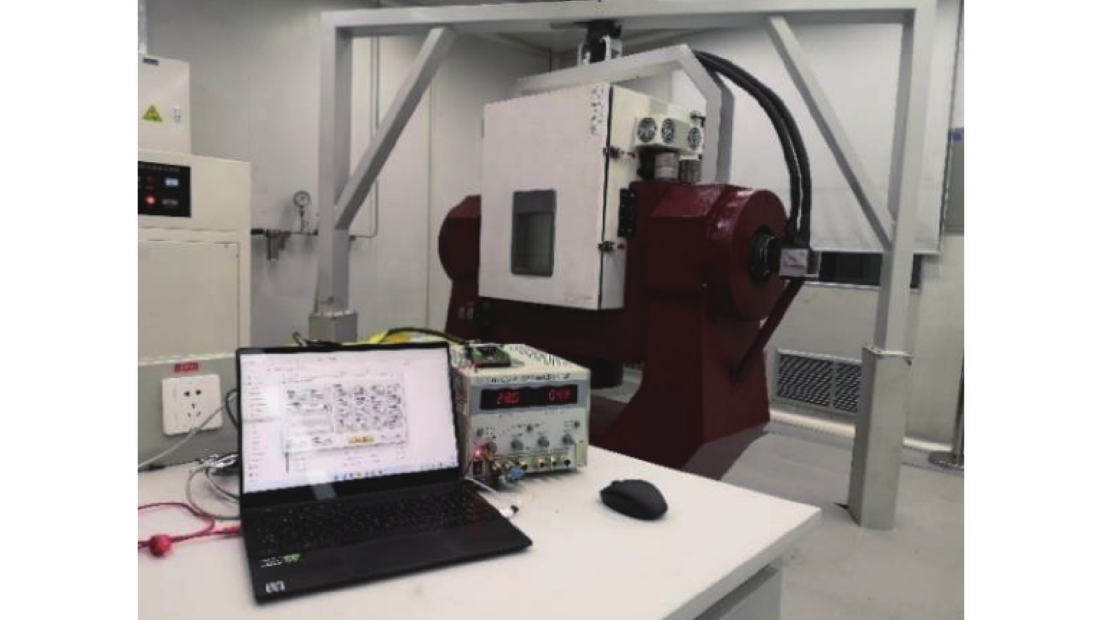
在仿真的基础上,将正四面体冗余惯性测量单元(Redundant Inertial Measurement Unit, RIMU)放置于三轴转台上进行实验,实验设备及环境如图3所示。

Figure 3. Experimental equipment and environment
正四面体RIMU装配的是型号为ZKDK70 MA的光纤陀螺仪和型号为JSD-I/B的石英挠性加速度计,具体技术参数如表5所示。实验中选取的三组位置和RRINS零偏估计仿真中选取的三组位置相同(表2)。每一组的两个位置分别采集1 min的数据。这样就可以计算得到三组不同位置下估计出的RRINS的惯性器件的零偏。
Parameter Gyro/(o)·h−1 Accelerometer Bias −10 - +10 $ \leqslant $3 mg Bias stability $ \leqslant $0.1 50 $ \text{μ} {\rm{g}} $ Table 5. Parameters of the experimental RIMU
-
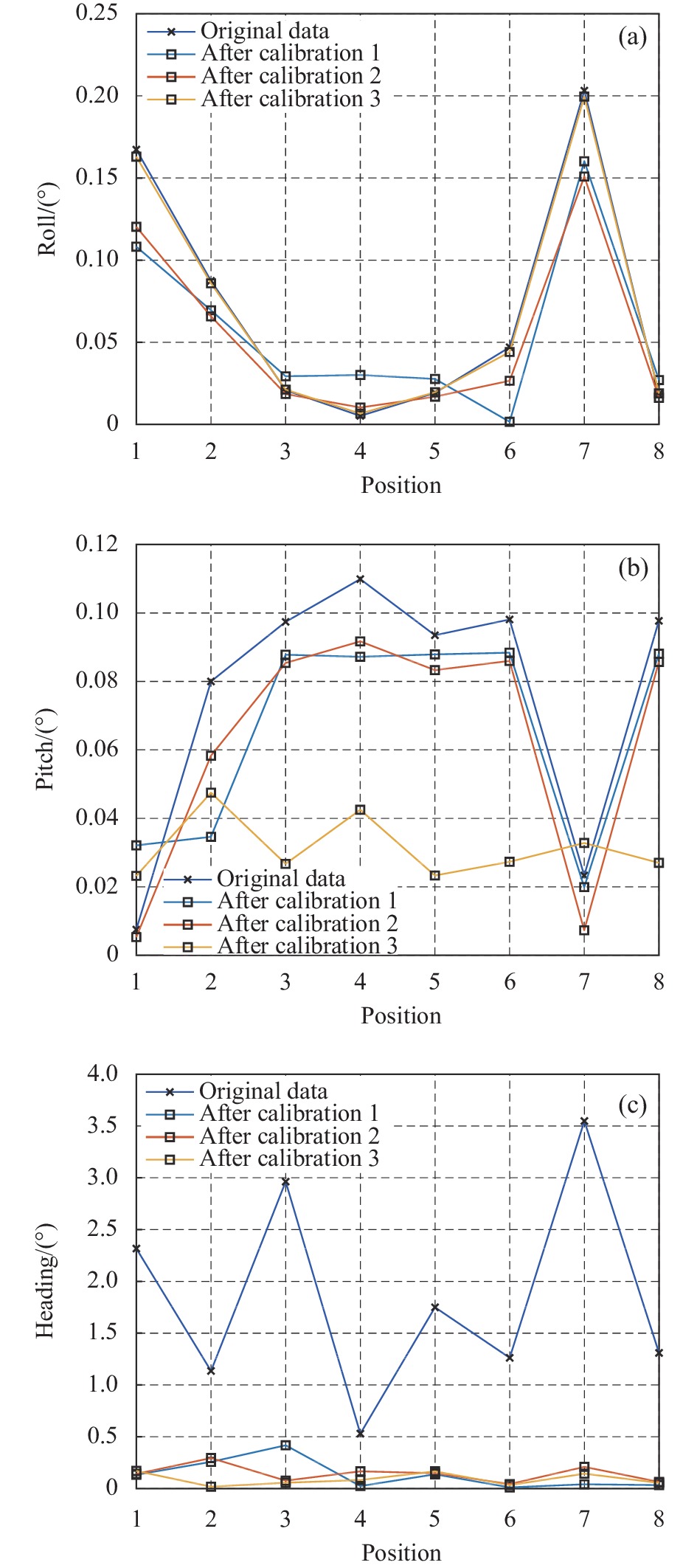
初始对准实验选取的位置和初始对准仿真选取的8个位置相同(表4),每个位置采集静态3 min的数据。首先将采集到的每个位置的原始数据进行粗对准,然后用RRINS零偏估计实验中估计出的三组零偏分别对8个位置的原始数据进行补偿做粗对准。将8个位置的原始数据进行粗对准的值和真实值的差值作为原始数据粗对准的误差,将8个位置的数据分别用三组零偏补偿后进行粗对准的值和真实值的差值作为三组数据补偿后粗对准的误差。
图4(a)、(b)、(c)所示分别是横滚角、俯仰角和航向角的粗对准误差比较。其中Original data, After calibration 1, After calibration 2和After calibration 3与初始对准仿真中所指代含义的不同点只在于其数据补偿的零偏是RRINS零偏估计实验中得到的三组零偏,而非仿真计算出的零偏。

Figure 4. (a) Coarse alignment experimental error of roll; (b) Coarse alignment experimental error of pitch; (c) Coarse alignment experimental error of heading
从图4(a)和图4(b)可以看出,数据补偿后横滚角和俯仰角的粗对准误差相比于未补偿数据的粗对准误差基本都有减小。未补偿数据粗对准误差和数据补偿后粗对准误差进行比较,其中横滚角误差减小幅度最大的从0.1673°减小到0.1082°,减小了0.0591°;俯仰角误差减小幅度最大的从0.0981°减小到0.0328°,减小了0.0708°。从图4(c)可以看出,未补偿数据航向角对准误差和数据补偿后航向角对准误差进行比较,减小幅度最大的从3.5482°减小到0.041°,减小了3.5072°,对准误差减小100倍左右。由于实验存在器件的随机噪声比较大;图4(b)中,三组位置估计出的零偏补偿后的对准误差出现一定的偏差波动也都是在噪声引起的对准偏差范围内的。综上,初始对准实验结果验证了基于两位置对准的冗余旋转惯导系统零偏估计方法的有效性。
-
初始对准后将冗余惯导系统放置于转台上连续采集1 h的静态数据,对采集的1 h的原始数据进行导航解算,另外用RRINS零偏估计实验中三组位置估计出的零偏分别对1 h原始数据补偿后的姿态、速度和位置变化进行解算。将三组位置估计出的零偏中的一组零偏对原始数据补偿后导航解算的姿态、速度和位置误差与原始数据的导航误差进行比较,结果如图5(a)~(c)所示。
从图5(a)可以看出,补偿后的RRINS的导航解算姿态的精度和稳定性都有提高。从图5(b)可以看出,原始数据解算出的东向速度和北向速度出现了很大的偏移,而数据补偿后解算出的结果的稳定性更好,并且精度有很大的提升。如图5(c)所示,进行1 h的导航,数据补偿后解算的纬度误差从0.1127°降低至0.0041°,经度误差从0.9374°降低至0.0633°。实验结果表明,数据补偿后,导航的精度和稳定性得到了有效的提升。
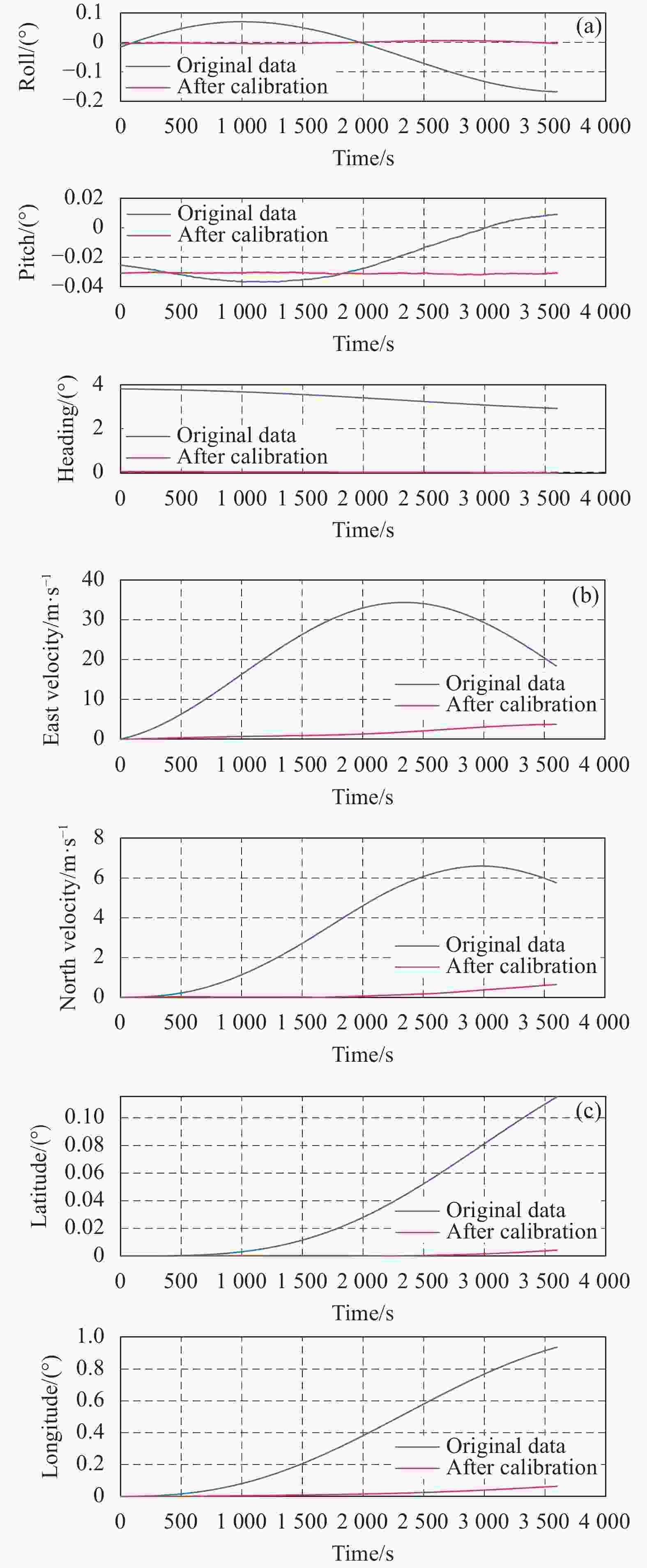
Figure 5. (a) Attitude error of navigation solution; (b) Velocity error of navigation solution ;(c) Position error of navigation solution
-
文中对冗余旋转惯导系统的两位置初始对准方法进行研究。首先通过惯性器件组合的方式构造不同组合下RRINS的零偏估计解析表达式,然后设计不同的RRINS两位置方式估计惯性器件的零偏,并基于每个惯性器件在不同组合下估计的零偏的均值补偿惯性器件输出,进行RRINS的初始对准。文中的两位置方案不要求转位机构必须严格旋转90°或180°,因此转位设计具有一定的普适性,并且整个零偏估计可以在2 min之内完成。仿真结果表明,该方法对陀螺仪的零偏估计误差在4%以内,加速度计的零偏估计误差基本在2%以内;横滚角的对准误差由0.016°减小到0.0002°,俯仰角的对准误差由0.012°减小到0.0012°,航向角的对准误差由0.11°减小到0.0012°。初始对准和静基座导航的实验结果表明该方法可有效提高初始对准的精度和导航精度,其中航向角的对准精度提高近100倍,纬度误差从0.1127°降低至0.0041°,经度误差从0.9374°降低至0.0633°。初始对准实验中少数位置零偏补偿后横滚角和俯仰角对准效果略不佳的原因有待进一步研究。该方法以正四面体冗余旋转惯导系统为例进行分析验证,同样也适用于其他冗余配置的旋转惯导系统,为冗余旋转惯导系统的高精度初始对准方法的研究提供了一定的参考。
Two-position initial alignment method for redundant rotating inertial navigation system
doi: 10.3788/IRLA20220414
- Received Date: 2022-03-25
- Rev Recd Date: 2022-04-27
- Publish Date: 2023-01-18
-
Key words:
- redundant rotating inertial navigation system /
- two-position alignment /
- error compensation /
- analytic alignment
Abstract: Redundant Rotating Inertial Navigation System (RRINS) can further improve the reliability of the system on the basis of traditional rotating inertial navigation system. Aiming at the high-precision initial alignment requirements of this type of system, A two-position initial alignment method was studied by taking the regular tetrahedral redundant rotating inertial navigation system as an example. Firstly, every three gyroscopes and three accelerometers constituted a combination. The zero bias correlation and redundancy configuration of the inertial device under each combination were established. And the RRINS two-position stop scheme was designed to estimate the zero bias of the corresponding inertial device. But in some special cases, the observation position needs to be increased. Then, the results obtained by each inertial device under different combinations were averaged, and the average value was used to compensate the measurement information of the corresponding inertial device. Finally, based on the compensated inertial device output performs the initial alignment of the RRINS. Mathematical simulation and experimental verification results show that the method can effectively estimate the zero bias of the inertial device under different two-position schemes. In the simulation, the bias estimation error of the gyroscope is within 4%, and the bias estimation error of the accelerometer is basically within 2%. Compared with the case without bias compensation, the initial alignment accuracy is improved by more than 10 times. In the experiment, the initial alignment accuracy in both horizontal and azimuth directions was improved, and the heading angle alignment error was reduced by about 100 times. At the same time, the method can also be extended to redundant rotating inertial navigation systems with other configuration schemes, which has certain reference significance for improving the initial alignment accuracy of such inertial navigation systems.


 DownLoad: