


 下载:
下载:


-
结构光三维测量与成像的理论与技术已取得快速发展,并被广泛应用于影视、游戏、虚拟现实、数字化博物馆、生产装配、工业检测、逆向工程、CAD建模制造等领域[1-3]。随着测量对象的复杂化和测量精度要求的不断提高,结构光三维测量与成像方法呈现的发展趋势:(1)尺度向大、小两级延伸,对象的拓扑、结构、材质趋于复杂多样化;(2)精度、速度要求不断提高;(3)方法向专业化、集成化发展;(4)网络多站式几何量测量、面向测量任务的组合测量方法呈现互补融合的态势;(5)高逼真度、高精度、高密度、高效三维测量与成像获取手段已成为未来发展趋势。
对于具有较大尺寸且形状、材质较复杂类物体,快速获取其高精度、高密度、高保真度三维信息具有一定的挑战性。以人体三维信息获取为例,其困难主要体现在:(1)人体尺寸较大,为获取其高密度数据需分多视场测量;(2)人体较难保持长时间静止不动,需要快速测量,而多视场测量会消耗更多时间;(3)人体各部位形状差异较大,各部位对测量数据的需求存在差异,例如脸部细节较多,往往需较高密度数据,而身体部位细节较少无需较高密度数据;(4)此外,类如头发类物体,其几何形状拓扑非常精细复杂,这一直是光学三维测量成像与数字化建模的难点[4-5]。文中将重点介绍多节点三维传感器测量网络相关技术,以解决较大尺寸物体的快速、高精度、高密度、高保真度三维信息获取与建模问题,其涉及到结构光三维测量基本原理介绍,以及多节点三维传感器测量网络的构建、标定及数据建模等相关技术。
-
结构光三维测量系统通常可分为单目(单个相机)系统和双目(两个相机)系统,同时包括一个结构光产生装置,该装置核心作用是为三维测量系统提供主动结构编码照明。结构光编码方式主要有黑白条纹编码、彩色条纹编码、散斑编码、相位编码等[6-9],其中相位编码具有空间连续性好、受环境光影响小的优势,其测量数据的精度和密度较好。本文后续介绍的测量网中单节点三维传感器采用相位编码方式,主要涉及两个关键技术环节。
-
条纹分析与相位重建目标是获取高精度的相位编码信息,其通常以条纹图案呈现,结构照明装置投射标准正弦光到物体表面,相机继而采集经物体表面调制的变形条纹图像,由条纹图像分析解调出包含物体深度信息的相位编码信息。按照所使用条纹图像的幅数,相位重建可分为单幅和多幅两类方法。单幅相位重建通常对条纹图进行空间变换,例如傅里叶变换[10-11],小波变换[12-13],希尔伯特变换[14]等,进而筛选出包含相位信息的特征区域。这类方法最显著的优势是适用于动态三维成像与测量,但面对深度不连续、表面纹理复杂及曲率变化较大的物体时精度和鲁棒性往往难以满足要求,限制了该类方法的应用范围。多幅相位重建技术是在时间维度上对相位信息进行编解码,例如被广泛应用的相移法[15-16]。多幅相位重建对测量环境具有较好的鲁棒性,且重建精度高,然而仅适用于静态物体。为突破多幅相位重建的速度限制,通过多波长复用将时间维信号编码在相机的不同颜色通道上,实现了基于彩色编码的快速三维成像与测量[17-18]。然而,彩色编码各通道间存在颜色串扰、响应不均匀以及对彩色纹理表面不鲁棒等问题。目前相位重建与条纹分析的一个研究趋势是利用软硬件对结构光进行调制,例如二值离焦投影[19-20]、阵列投影[21]和声光调制[22]等,从而大幅度提升投影速率,实现高速三维成像与测量。但离焦投影或激光散斑降低了条纹图像的信噪比,使得相位重建精度较低。从20世纪80年代至今,同时兼顾高精度、高速度和高鲁棒性的相位重建和条纹分析仍具有一定挑战性。
-
相位信息被物体的深度信息所调制,因此,基于相位编码的三维重建方法可分为两类:一类是进一步从相位信息中解调出物体的深度信息,即相位-深度映射[23-28];另一类是将相位信息作为编码特征点进行三维重建,即立体视觉[29-33]。对于一个三维成像与测量系统,相位与深度之间存在特定的映射关系,通过系统标定确定相位-深度映射系数之后,相位可以直接映射到深度,实现高效、高精度的三维重建。这种高效的转换取决于系统的几何结构,比如使用参考面,光轴共面或垂直于参考面等,而且需要使用精密位移台或量块获取一系列深度值进行标定,这些因素限制着这类方法的实际应用。相反,根据光路的可逆性,结构照明装置可视为逆向相机,与实际相机组成一个双(多)目成像系统,并且相位信息提供了同名点的编码特征,利用立体视觉即可实现三维重建。立体视觉的系统结构具有更多的自由度,并且可以借助相机模型进行灵活、有效的系统建模和标定。然而,立体视觉需要耗费较大的时间代价进行对应点搜索,三维重建效率明显低于相位-深度映射。近几年来,研究人员提出了一些相位-深度映射和立体视觉相结合的方法[34-36],一方面在相位-深度映射中引入相机标定方法,另一方面在立体视觉中建立相位-深度(三维)映射模型,旨在实现高精度、高效和灵活的三维成像与测量。
-
在测量尺寸较大、拓扑复杂的物体(如大尺寸薄壁件),或者对表面测量有时间要求(如人体测量)时,利用多个双目结构光三维传感器搭建多测量节点光学三维测量网能在一定测量空间内实现快速和自动化的全空间测量[37-40]。此节主要涉及测量网构建相关的两个关键问题:多节点测量网的结构设计和节点网络规划。
-
该部分以组网便携性为指导,优化系统硬件结构设计,实现即插即用式节点扩展功能;进一步优化测量网络各节点三维传感器的工作时序,实现节点间结构光照明无串扰时同时序工作,有串扰时分时序工作;优化三维测量数据的传输模式,减少数据传输占整体测量时间的比重。
该测量网采用单节点三维传感器作为独立基站,由于基站调控的相互独立性,有利于整体系统调试和灵活扩展应用。同时建立控制中心,利用千兆网络实现基站和控制中心之间控制指令和测量数据的传输。图1为网络结构示意图,每个基站采用双目结构系统,采用即插即用式设计,实物如图2所示,可根据测量需求,自适应增加减少节点传感器数量。各基站与控制中心在TCP/IP网络环境下采用客户端-服务器方式实现网络通信。控制中心主机运行服务器程序,各个基站主机运行客户端程序,建立双向通信关系,各个客户端接收由服务器发出的不同控制指令并作出相应响应,严格控制工作时序;客户端也能通过服务器的IP地址和网络端口将得到的数据传输至服务器,控制中心作进一步的后处理。

图 1 测量网结构示意图
Figure 1. Schematic diagram of measurement network structure

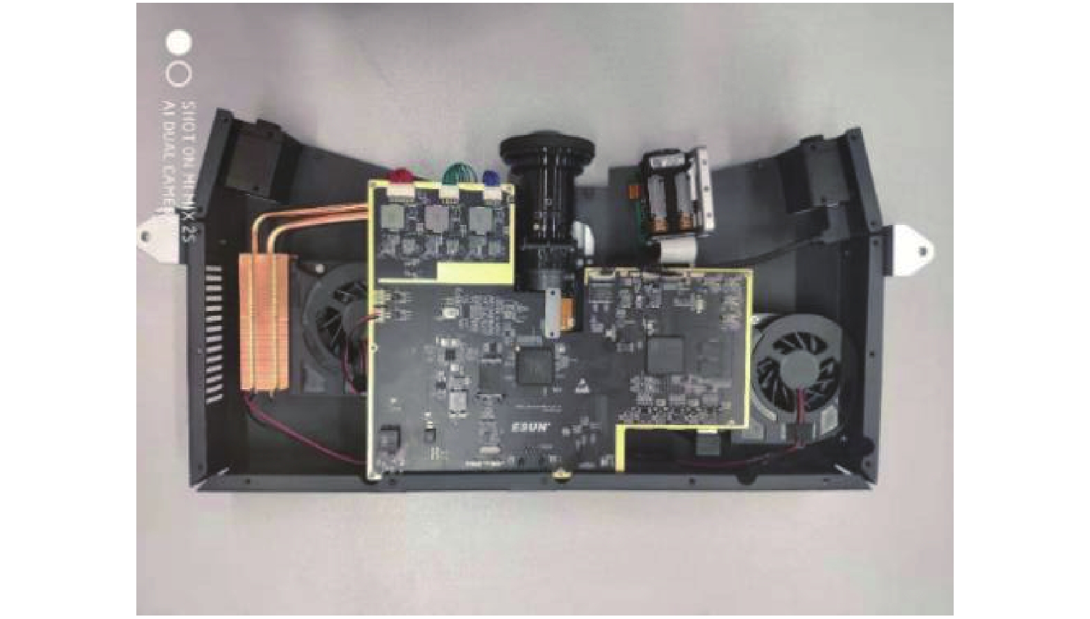
图 2 单节点三维传感器
Figure 2. 3D sensor on one node
为提升测量网络工作效率,一方面,提升单节点三维传感器采集效率,采用条纹投影采集一体化控制方案,实现条纹投影与相机采集的同步,开发的图2型号三维传感器可实现360 fps的图像采集速率;另一方面,协调测量网络各不同基站的工作时序,压缩整体系统深度像采集的时间,发挥分布网络的计算优势,利用时间复用的思想,通过软件系统控制各个基站,流水实现分布式组合三维成像系统。
-
为了适应大尺寸、拓扑结构复杂物体的高精度三维彩色数据获取,充分考虑被测物体与测量网络的空间几何结构以及光学成像参数影响,需构建基于物体空间几何特征和表面反射特性关联优化的多节点三维传感器测量网络规划方案[41-43]。其中重点构建两个空间约束条件:工作空间约束,即节点三维传感器位置必落在整个工作区范围内;测量空间约束,即对任意测量点至少落在一个节点三维传感器测量范围内,如图3所示。通常工作空间约束较少,基本能够满足,而测量空间约束较为苛刻复杂,需要基于可见性、可视角/入射角、重叠、遮挡、视场、焦距/景深、像素分辨率、图像对比度/传感器动态范围诸多测量影响因素研究三维传感器测量网络的空间约束条件和整体测量误差最小评定原则,制定出参数求解的优化算法。

图 3 测量网络的规划
Figure 3. Planning of measurement network
-
文中结合实际情况,重点考虑三维传感器可见性、视场角、景深、投影仪约束、遮挡、禁止区域等约束条件,如图4所示。

图 4 测量空间约束条件
Figure 4. Measurement space constraints
(1)可见性约束:物体表面上物点P的法向量与该点的视线方向向量点乘值小于0,则满足可见性,如图4(a)。
(2)视场角约束:受传感器面积和镜头焦距的限制,视觉传感器只能采集特定视角内的图像,该视场区域一般为四棱锥形,如图4(b)。另对于双目立体视觉系统需要考虑双目视场的叠加,如图4(c)。
(3)景深约束:在物方焦平面前后能够清晰成像的范围称为景深,相机景深与焦距、对焦距离、光圈值等参数密切相关。经过景深约束后,相机视场范围为一个四棱台。对于双目系统,如图4(d)。
(4)遮挡约束:可分为两种情况:一种是传感器和物体之间存在其他阻碍物;另一种是物体自身的某些部分不规则,存在遮挡,致使无法拍摄到。
(5)禁止约束:即传感器无法到达的区域,即前面所述工作空间约束。
-
为简化模型,采用一种顺序迭代方法逐步实现基于已知物体模型的视点规划,算法流程如下,流程图如图5所示。
(1)根据被测物体模型抽取控制点云以表征测量空间,选取物体点云模型中的Xmax、Xmin、Ymax、Ymin和Zmax、Zmin,计算候选视点区域的大小。候选视点空间中的每一个网格点看作是视点候选位置。
(2)对每个候选视点位置进行景深和可见性约束,计算并保存满足约束条件的点云。
(3)以候选视点空间中的每个点云为中心,统计满足视场角约束的点云数量,比较满足三个约束的候选视点指向某点云的数量,数量最大的位置确定为视点位置,并通过视点位置和指向该点云的方向确定视线方向。
(4)对点云数量差值在阈值范围内的候选视点进行遮挡约束判定,进一步确定满足约束条件候选视点。遮挡约束的判定:在候选点云中随机取n个点云,将传感器位置与随机点云之间n等分,取每个分割点的K邻域点云,进行遮挡判断。分别计算几个候选视点中遮挡点云的数量,遮挡数量最少的候选视点确定为传感器的视点位置。
(5)确定了一个视点位置和视线方向后,去除已选的点云,重复进行以上操作,依次确定多个视点的位置和视线方向。
(6)当剩下的点云数量小于设定的阈值时,认为基本上全部覆盖,算法终止。

图 5 视点规划流程图
Figure 5. Flow chart for views planning
图6为一大尺寸水缸的视点规划实验结果。

图 6 视点规划结果
Figure 6. Result of views planning
-
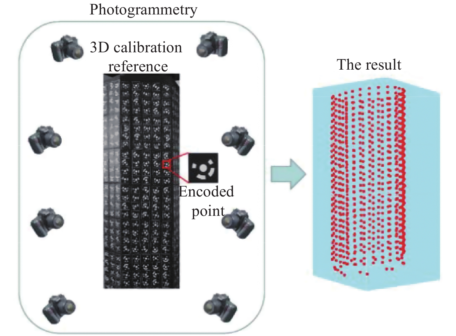
针对大尺寸标定基准参照物加工困难问题,采用自适应立体标靶制作方案,即根据测量空间尺寸,构建编码标志点参照物,利用近景摄影测量技术构建立体标定基准。以人体测量为例,立体标靶采用刚体多面立柱体,并在每一面上粘贴环状编码标志点,构成立体标靶。该部分涉及编码标志点的自动识别、圆心校正、光束平差等相关技术[44-47]。其主要步骤如下:
(1)用高分辨了数码相机(尼康D200)在58个不同的视角拍摄获得标靶图像,如图7所示(部分视角拍摄的图像)。

图 7 立体标靶构建结果
Figure 7. Result of 3D calibration reference
(2)对标靶图像中的编码标志点进行中心定位和解码,根据每个编码点不同的编码值获得其在不同图像之间的对应关系和图像坐标。 (3)利用光束平差(Bundle Adjustment,BA)方法,每个不同编码的世界坐标Xj在拍摄视角i下的重投影的图像坐标为 ${{\overset{\frown} m} _{ij}}(K,\theta ,{r_i},{t_i},{X_j})$ ,优化该重投影误差,如公式(1)所示。$${\rm{cost}}(\varepsilon ) = \sum\limits_{i = 1}^N {\sum\limits_{j = 1}^M {\left\{ {\;{{\left\| {{{\hat m}_{ij}} - {{\overset{\frown} m}_{ij}}(K,\theta ,{r_i},{t_i},{X_j})} \right\|}^2}} \right\}} } $$ (1) 式中:
$(K,\theta )$ 为摄像机的内部结构参数(K为线性内参:焦距、主点、倾斜因子,θ为镜头畸变的非线性内参:径向畸变、切向畸变等);$({r_i},{t_i})$ 为摄像机拍摄的位姿(旋转和平移的6个自由度外部参数);${\hat m_{ij}}$ 为该点圆心图像坐标,由此可得不同编码点的世界坐标Xj,完成标靶校正,如图7所示。 -
对于多节点三维传感器标定较为普遍的标定方案为分步标定法,即先对各个节点三维传感器逐一标定出其内部参数,再确定出各个节点传感器之间的外部结构参数。该方案思想较简洁明了,但由于该方案需对每个节点传感器逐一操作,较为繁琐、耗时、非自动化,而且,外部结构参数的确定仍需额外方法。由于文中三维传感器采用双目结构系统,并借助三维立体标靶,即可实现各节点传感器内部参数与各节点之间外部结构参数同时标定。因此,可将复杂的多节点三维传感器网络标定问题转化为多相机网络标定问题,减少了系统标定的复杂性。
将校正后的标靶置于三维成像系统的测量空间之内,控制系统内的各摄像机采集标靶的图像,根据图像中的标志点标定系统内各摄像机的参数以及各摄像机之间的相互坐标变换关系,完成系统的标定,如图8所示。而测量网的标定是解决问题的关键,每个摄像机的标定是测量网标定的基础,对测量网中第k台摄像机进行标定需要求解如下最优化问题:
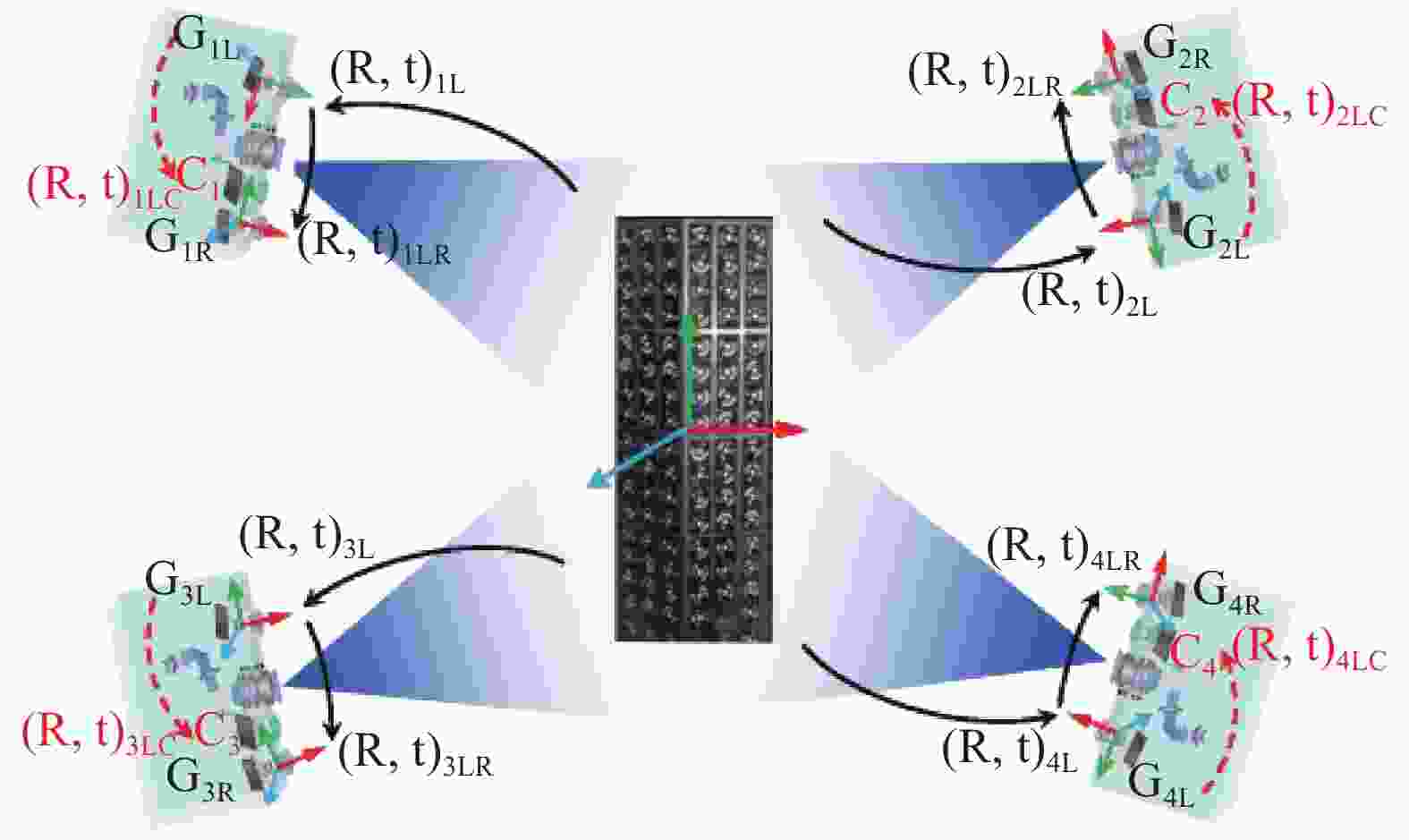
图 8 测量网的同步标定
Figure 8. Calibration for measurement networks
$$ \mathop {\min }\limits_{K,\theta ,r,t} \sum\limits_{j = 1}^n {\left\{ {\,{{\left\| {{{\hat m}_j} - {\overset{\frown} m} (K,\theta ,r,t;{X_j})} \right\|}^2}} \right\}} $$ (2) 式中:
$\hat m$ 为基准点图像坐标;${\overset{\frown} m} $ 为由摄像机的非线性模型重投影得到的图像坐标,对摄像机获取的n个所有不同标志点的反投影误差求和即可得公式(2)所示的目标函数。其中,需要确定三维基准点Xj与其图像坐标
${\hat m_j}$ 的对应关系,该处通过环形编码实现,即解码获得每个基准的不同的编码值。在实际应用中,由于遮挡等原因,存在大量编码识别错误,造成对应点错误影响标定结果。为此,提出一种基于随机抽样一致(Random Sample Consensus,RANSAC)算法的局外点剔除方法。为简化一致性条件,仅采用摄像机的线性投影模型,Xj与${\hat m_j}$ 之间的对应关系可以表示为:$$ {\tilde m_j} = M \cdot {\tilde X_j} $$ (3) 式中:
${\tilde m_j}$ 、${\tilde X_j}$ 分别为基准点图像坐标和三维坐标的齐次坐标表示;M为大小为3×4的投影矩阵。能正确解码的基准点都能符合公式(3)模型,称之为“局内点”;受遮挡的编码点不能得到正确的编码值,不能符合公式(3)模型称之为“局外点”。理论上,如果每台摄像机能够一次拍摄到标定靶中足够多的非共面基准点,即可完成摄像机的标定和测量网的标定。为了进一步提高标定结果的可靠性,在实际标定中,通常改变标靶的姿态拍摄M组图像,利用多组图像以提供更多的约束方程,能更准确地优化摄像机内外参和畸变系数,有助于得到更稳定的传感器节点的结构参数和外参。对于某一节点i而言,将双目传感器的结构参数和该节点的外参作为待优化的参数向量,构造新的优化目标函数:
$$\begin{split} \cos t({\tau _i}) =\;& \sum\limits_{t = 1}^N \sum\limits_{s = 1}^M \{ {{\left\| {{{\hat m}_l}^{st} - {{\overset{\frown} m}_l}^{st}(K_l^i,\theta _l^i,r_s^i,t_s^i;{X_w})} \right\|}^2} + \\ & {{\left\| {{{\hat m}_r}^{st} - {{\overset{\frown} m}_r}^{st}(K_r^i,\theta _r^i,{r^i},{t^i},r_s^i,t_s^i;{X_w})} \right\|}^2}\} \end{split}$$ (4) 式中:上标s为系统的第s个拍摄姿态,t为标靶中第t个基准点;
${\tau _i} = \{ K_l^i,\theta _l^i,K_r^i,\theta _r^i,{r^i},{t^i},r_s^i,t_s^i\} $ 为传感器节点i待优化的参数向量,$\{ K_l^i,\theta _l^i\} $ 、$\{ K_r^i,\theta _r^i\} $ 分别为该节点i左右摄像机的内参和畸变,${r^i},{t^i}$ 为双目系统的结构参数,$r_s^i,t_s^i$ 为左摄像在第s次拍摄姿态下的外参;$\hat m_{l/r}^{st}$ 为左右摄像机中基准点的图像坐标;${{\overset{\frown} m} _l}^{st}( \bullet )$ 、${{\overset{\frown} m} _r}^{st}( \bullet )$ 为重投影图像坐标。通过最小化目标函数公式(4),实现对系统参数的最优化估计,得到该节点的结构参数$r_s^i,t_s^i$ ,用于公式实现该节点i的深度重建;将一次拍摄时标靶坐标系为全局世界坐标系,${r^i},{t^i}$ 则表示为节点i与全局世界坐标系变换关系,可用于后期不同传感器测量数据的初始匹配。 -
为获取物体完整三维模型,需将不同视场获取物体深度数据与纹理数据进行匹配与融合操作。对于深度数据匹配应用最为广泛的是迭代最近点(ICP)方法[48],该方法对高密度数据匹配精度高、但计算量大、对初值敏感。为解决初值问题先后发展了诸多粗匹配方法,如借助标志点、基于三维几何特征(旋转图像(spin image)、点签名(point signature)、双切线(bi-tangent curves)、曲面的曲率以及平面和特征线等等)、基于二维纹理特征(图像相关、SIFT等)、基于机械手等仪器设备等[49-50]。对多视场深度数据的融合方法,主要有基于缝合思想和隐函数思想两种方法[50]:基于缝合方法的优点是计算量不大,但重叠区域的识别和保持接缝处的连续性、光滑性较为困难。基于隐函数方法主要通过构造带有符号的距离函数,采用不同的体绘制算法来提取所需要的多边形网格。该类方法能够保持接缝处光滑,但计算复杂度较高。相较于前期三维传感,该部分属于后期建模,属计算机图形学领域,相对较为独立。但文中介绍的多节点三维传感器测量网络,尤其是网络标定相关技术及输出参数,为该部分实现多传感器测量数据的自动匹配提供了帮助。下面逐一简要介绍相关处理方案[51-60]。
-
由3.2部分可知,测量网标定结果参数包含各节点三维传感器间的外部参数,即为各传感器测量三维深度数据间的旋转平移刚体变换参数。该参数可作为数据匹配的初始估计,结合一种迭代全局ICP方法以减少匹配误差积累。匹配的误差积累主要来源于测量网内部多个三维传感器之间测量数据的匹配误差(各节点传感器间标定误差)、测量网多视场测量数据间的匹配误差(对于物体相对于测量网变换角度,产生多视场数据情况)、及其两者相衔接的匹配误差。
全局ICP迭代算法如下:
输入:所有视场的三维点集合
${V_i}$ 到世界坐标系的变换矩阵${M_i}$ ,$i = 1,2...n$ ;输出:优化后的各视场三维点集合
${V_i}$ 到世界坐标系的变换矩阵${M_i}$ ,$i = 1,2...n$ ;迭代优化:
While (no converges){ /*收敛条件:
$\forall \Delta {M_i}{\rm{, }}\left\| {\Delta {M_i} - I} \right\| <$ $ \varepsilon $ */For (i = 1; i<n; i++){
1、提取与
${V_i}$ 匹配的所有点对;2、将点转换到世界坐标系;
3、计算转换矩阵
$\Delta {M_i}$ ;4、
${M_i} = \Delta {M_i} \cdot {M_i}$ ;}
}
此外,为加快收敛速度,采用一种多分辨的采样方法,由低分辨逐渐向高分辨过渡,以减少ICP运算时间。具体方法可参见文献[54-56],此处不再展开。
-
当前三维深度数据融合方法较为成熟,且随着三维传感技术发展,三维深度数据精度和质量也愈高,故融合模型基本无问题。而纹理数据获取受环境照明影响较大,尤其对于测量网的各节点传感器均从不同角度获取纹理数据,照明差异尤为明显。为此,为获取物体高保真度、高精度的颜色信息,构建光照系统及颜色采集系统,对光源、物体及传感器进行高精度标定。一方面,根据测量物体、系统及环境等因素,设计LED阵列光源,建立测量空间无影人工日光控制,从而最大程度获取均匀照明,为高保真颜色信息获取提供环境支持。另一方面,由3.2节测量网络标定处理可将纹理相机的内外参数同时标定,即可获取亚像素级深度纹理映射,该部分内容可参见相关标定论文。基于三维融合模型及纹理映射关系即可实现纹理融合,即将各传感器纹理数据进行颜色校正、接缝平滑、插值平均等处理,为三维模型生成整张纹理映射图。课题组前期提出了基于复合权重的纹理数据融合方案,根据相机相对几何模型的姿态、空间几何模型以及几何模型投影到纹理图侧影轮廓等信息,构造几何三角面片在各个子纹理图中的颜色权重,采用法向量权重、边缘权重、深度权重相结合的方式定义复合权重,客观的衡量物体在采集纹理图中的颜色置信度。
图9(a)为基于文中多节点三维传感器测量网络相关技术构建的人体三维测量与成像系统原型机,该系统设置10个节点传感器,网络设计与控制系统采用文中第2节相关技术,实现了1 s内获取人体深度与纹理原始数据;系统标定采用文中第3节相关技术,立体标靶重建精度0.01 mm内,多节点传感器标定精度在0.1 mm内;并实现了全自动人体深度纹理数据融合及后处理,图9(b)为融合结果。

图 9 人体三维测量与成像
Figure 9. 3D measurement and imaging for human body
-
阐述了基于条纹相位结构光的多节点三维传感器测量网络相关技术,涉及到了网络构造与规划、网络标定、网络数据融合等问题。在解决中大尺寸物体的自动化、快速三维测量及工业检测具有较大应用价值;为结构光三维传感技术发展提供了补充式理论与实践探索。文中内容涉及三维传感、条纹分析、摄像机标定、深度重建、网络规划、近景摄影测量、图像识别、深度数据匹配、纹理融合等相关知识,由于篇幅限制,诸多技术细节未能展开阐述,具体可参考相关文献。
Techniques of structured light measurement network with 3D sensors
-
摘要:
针对大尺寸复杂物体的全自动、高精度、大数据密度、真彩色三维成像与测量,基于条纹结构光三维传感器,阐述了多节点三维传感器测量网络相关技术。涉及单三维传感器的条纹分析和相位重建、系统标定和三维重建两大关键技术点分析,多节点三维传感器测量网络的构建与优化、多节点三维传感器测量网络的标定、测量三维深度数据与纹理数据的匹配与融合等相关技术。并给出了部分实验原型机及实验结果。
Abstract:For achieving automatic, high-precision, high-density, and photorealistic 3D imaging and measurement of large-scale complex objects, the techniques about multi-node 3D sensor measurement network were described based on 3D sensing with the fringe structured light. It mainly involved the analysis of two key technologies (fringe analysis and phase reconstruction, system calibration and 3D reconstruction) of single 3D sensing, construction and optimization of multi-node 3D sensor measurement network, calibration of multi-node 3D sensor measurement network, matching and fusion of 3D depth data and texture data. Some experimental prototypes and experimental results were given.
-
[1] Sansoni G, Trebeschi M, Docchio F. State-of-the-art and applications of 3D imaging sensors in industry, cultural heritage, medicine, and criminal investigation [J]. Sensors, 2009, 9(1): 568−601. doi: 10.3390/s90100568 [2] Schwenke H, Neuschaefer-Rube U, Pfeifer T, et al. Optical methods for dimensional metrology in production engineering [J]. CIRP Annals-Manufacturing Technology, 2002, 51(2): 685−699. doi: 10.1016/S0007-8506(07)61707-7 [3] Blais F. Review of 20 years of range sensor development [J]. Journal of Electronic Imaging, 2004, 13(1): 231−240. doi: 10.1117/1.1631921 [4] Daanen H A M, TerHaar F B. 3D whole body scanners revisited [J]. Displays, 2013, 34: 270−275. doi: 10.1016/j.displa.2013.08.011 [5] Tong J, Zhou J, Liu L, et al. Scanning 3D full human bodies using kinects [J]. IEEE Transactions on Visualization and Computer Graphics, 2012, 18(4): 643−650. doi: 10.1109/TVCG.2012.56 [6] Geng J. Structured-light 3D surface imaging: A tutorial [J]. Advances in Optics and Photonics, 2011, 3(2): 128−160. doi: 10.1364/AOP.3.000128 [7] He Jinying, Liu Xiaoli, Peng Xiang, et al. Integer pixel correlation searching for three-dimensional digital speckle based on gray constraint [J]. Chinese Journal of Lasers, 2017, 44(4): 150−157. (in Chinese) [8] Tang Q, Liu C, Cai Z, et al. An improved spatiotemporal correlation method for high- accuracy random speckle 3D reconstruction [J]. Optics and Lasers in Engineering, 2018, 110: 54−62. doi: 10.1016/j.optlaseng.2018.05.007 [9] Zuo C, Tao T, Feng S, et al. Micro Fourier Transform Profilometry (μFTP): 3D shape measurement at 10,000 frames per second [J]. Optics and Lasers in Engineering, 2018, 102: 70−91. doi: 10.1016/j.optlaseng.2017.10.013 [10] Takeda M, Mutoh K. Fourier transform profilometry for the automatic measurement of 3-d object shapes [J]. Applied Optics, 1983, 22(24): 3977−3982. doi: 10.1364/AO.22.003977 [11] Zuo C, Feng S, Huang L, et al. Phase shifting algorithms for fringe projection profilometry: a review [J]. Optics and Lasers in Engineering, 2018, 109: 23−59. doi: 10.1016/j.optlaseng.2018.04.019 [12] Zhong J, Weng J. Spatial carrier-fringe pattern analysis by means of wavelet transform: Wavelet transform profilometry [J]. Applied Optics, 2004, 43(26): 4993−4998. doi: 10.1364/AO.43.004993 [13] Ma J, Wang Z, Pan B, et al. Two-dimensional continuous wavelet transform for phase determination of complex interferograms [J]. Applied Optics, 2011, 50(16): 2425−2430. doi: 10.1364/AO.50.002425 [14] Sutton M A, Zhao M, Mcneill S R, et al. Development and assessment of a single-image fringe projection method for dynamic applications [J]. Experimental Mechanics, 2001, 41(3): 205−217. doi: 10.1007/BF02323136 [15] Srinivasan V, Liu H C, Halioua M, et al. Automated phase-measuring profilometry of 3-d diffuse objects [J]. Applied Optics, 1984, 23(18): 3105−3108. doi: 10.1364/AO.23.003105 [16] Peng J, Liu X, Deng D, et al. Suppression of projector distortion in phase-measuring profilometry by projecting adaptive fringe patterns [J]. Optics Express, 2016, 24(19): 21846−21860. doi: 10.1364/OE.24.021846 [17] Pan J, Huang P S, Chiang F P. Color-coded binary fringe projection technique for 3-D shape measurement [J]. Optical Engineering, 2005, 44(2): 023606. doi: 10.1117/1.1840973 [18] Zhang Z, Towers C E, Towers D P. Time efficient color fringe projection system for simultaneous 3D shape and color using optimum 3-frequency selection [J]. Optics Express, 2006, 14(14): 6444−6455. doi: 10.1364/OE.14.006444 [19] Zuo C, Chen Q, Gu G, et al. High-speed three-dimensional shape measurement for dynamic scenes using bi-frequency tripolar pulse-width-modulation fringe projection [J]. Optics and Lasers in Engineering, 2013, 51: 953−960. doi: 10.1016/j.optlaseng.2013.02.012 [20] Lei S, Zhang S. Flexible 3-D shape measurement using projector defocusing [J]. Optics Letters, 2009, 34(20): 3080−3082. doi: 10.1364/OL.34.003080 [21] Heist S, Mann A, Kühmstedt P, et al. Array projection of aperiodic sinusoidal fringes for high-speed three-dimensional shape measurement [J]. Optical Engineering, 2014, 53(11): 112208. doi: 10.1117/1.OE.53.11.112208 [22] Guan Y, Yin Y, Li A, et al. Dynamic 3D imaging based on acousto-optic heterodyne fringe interferometry [J]. Optics Letters, 2014, 39(12): 3678−3681. doi: 10.1364/OL.39.003678 [23] Du H, Wang Z. Three-dimensional shape measurement with an arbitrarily arranged fringe projection profilometry system [J]. Optics Letters, 2007, 32(16): 2438−2440. doi: 10.1364/OL.32.002438 [24] Huang Z, Xi J, Yu Y, et al. Improved geometrical model of fringe projection profilometry [J]. Optics Express, 2014, 22(26): 32220−32232. doi: 10.1364/OE.22.032220 [25] Zhang Z, Ma H, Zhang S, et al. Simple calibration of a phase-based 3D imaging system based on uneven fringe projection [J]. Optics Letters, 2011, 36(5): 627−629. doi: 10.1364/OL.36.000627 [26] Asundi A, Wensen Z. Unified calibration technique and its applications in optical triangular profilometry [J]. Applied Optics, 1999, 38(16): 3556−3561. doi: 10.1364/AO.38.003556 [27] Huang L, Chua P S K, Asundi A. Least-squares calibration method for fringe projection profilometry considering camera lens distortion [J]. Applied Optics, 2010, 49(9): 1539−1548. doi: 10.1364/AO.49.001539 [28] Léandry I, Brèque C, Valle V. Calibration of a structured-light projection system: development to large dimension objects [J]. Optics and Lasers in Engineering, 2012, 50(3): 373−379. doi: 10.1016/j.optlaseng.2011.10.020 [29] Legarda-Sáenz R, Bothe T, Jüptner W P. Accurate procedure for the calibration of a structured light system [J]. Optical Engineering, 2004, 43(2): 464−471. doi: 10.1117/1.1635373 [30] Yin Y, Peng X, Li A. Calibration of fringe projection profilometry with bundle adjustment strategy [J]. Optics Letters, 2012, 37(4): 542−544. doi: 10.1364/OL.37.000542 [31] Zhang S, Huang P S. Novel method for structured light system calibration [J]. Optical Engineering, 2006, 45(8): 083601. doi: 10.1117/1.2336196 [32] Chen X, Xi J, Jin Y, et al. Accurate calibration for a camera-projector measurement system based on structured light projection [J]. Optics and Lasers in Engineering, 2009, 47(3-4): 310−319. doi: 10.1016/j.optlaseng.2007.12.001 [33] Chen R, Xu J, Chen H, et al. Accurate calibration method for camera and projector in fringe patterns measurement system [J]. Applied Optics, 2016, 55(16): 4293−4300. doi: 10.1364/AO.55.004293 [34] Vargas J, Quiroga J A, Terron-Lopez M J, et al. Flexible calibration procedure for fringe projection profilometry [J]. Optical Engineering, 2007, 46(2): 023601. doi: 10.1117/1.2709855 [35] Huang J, Wu Q. A new reconstruction method based on fringe projection of three-dimensional measuring system [J]. Optics and Lasers in Engineering, 2014, 52: 115−122. doi: 10.1016/j.optlaseng.2013.07.002 [36] Cai Z, Liu X, Li A, et al. Phase-3D mapping method developed from back-projection stereovision model for fringe projection profilometry [J]. Optics Express, 2017, 25(2): 1262−1277. doi: 10.1364/OE.25.001262 [37] Guo J, Peng X, Li A, et al. Automatic and rapid whole-body 3D shape measurement based on multinode 3D sensing and speckle projection [J]. Applied Optics, 2017, 56(31): 8759−8768. doi: 10.1364/AO.56.008759 [38] Peng X, Liu X, Yin Y, et al. Optical measurement network for large-scale and shell-like objects [J]. Optics Letters, 2011, 36(2): 157−159. doi: 10.1364/OL.36.000157 [39] Liu X, Peng X, Chen H, et al. Strategy for automatic and complete three-dimensional optical digitization [J]. Optics Letters, 2012, 37(15): 3126−3128. doi: 10.1364/OL.37.003126 [40] Liu Xiaoli, Peng Xiang, Yin Yongkai, et al. 3D auto-inspection for large thin-wall object [J]. Acta Optica Sinica, 2011, 31(3): 0312006. (in Chinese) doi: 10.3788/AOS201131.0312006 [41] Chen S Y, Li Y F. Automatic sensor placement for model-based robot vision [J]. Part B: Cybernetics, IEEE Transactions on Systems, Man, and Cybernetics, 2004, 34(1): 393−408. doi: 10.1109/TSMCB.2003.817031 [42] Tarabanis K A, Allen P K, Tsai R Y. A survey of sensor planning in computer vision [J]. IEEE Transactions on Robotics and Automation, 1995, 11(1): 86−104. doi: 10.1109/70.345940 [43] Scott W R. Model-based view planning [J]. Machine Vision and Applications, 2009, 20(1): 47−69. doi: 10.1007/s00138-007-0110-2 [44] Liu X, Cai Z, Yin Y, et al. Calibration of fringe projection profilometry using an inaccurate 2D reference target [J]. Optics and Lasers in Engineering, 2017, 89: 131−137. doi: 10.1016/j.optlaseng.2016.05.025 [45] He D, Liu X, Peng X, et al. Eccentricity error identification and compensation for high-accuracy 3D optical measurement [J]. Measurement Science and Technology, 2013, 24(7): 075402. doi: 10.1088/0957-0233/24/7/075402 [46] Yin Yongkai, Liu Xiaoli, Li Ameng, et al. Sub-pixel location of circle target and its application [J]. Infrared and Laser Engineering, 2008, 37(4): 47−50. (in Chinese) [47] Yin Y, Peng X, Liu X, et al. Calibration strategy of optical measurement network for large-scale and shell-like objects [J]. Optics Communications, 2012, 285(8): 2048−2056. doi: 10.1016/j.optcom.2011.12.100 [48] Besl P J, McKay N D. A method for registration of 3D shapes [J]. IEEE Transactions on Pattern Analysis and Machine Intelligence, 1992, 14(2): 239−256. doi: 10.1109/34.121791 [49] Salvi J, Matabosch C, Fofi D, et al. A review of recent range image registration methods with accuracy evaluation [J]. Image and Vision Computing, 2007, 25(5): 578−596. doi: 10.1016/j.imavis.2006.05.012 [50] Liu Xiaoli. Key techniques in multiple range images modeling [D]. Tianjin: Tianjin University, 2008. (in Chinese) [51] Liu X, Peng X, He D, et al. Automatic 3D imaging and modeling system with color information for cultural heritage digitization [C]//Fringe 2013, 2013: 821-826. [52] Li A, Peng X, Yin Y, et al. Optical 3D digitizer for photorealistic imaging of movable cultural heritage [J]. Acta Photonica Sinica, 2013, 42(12): 1421−1429. (in Chinese) doi: 10.3788/gzxb20134212.1421 [53] Liu X, Peng X, Yin Y, et al. Generation of photorealistic 3D image using optical digitizer [J]. Applied Optics, 2012, 51(7): 1304−1311. [54] Liu Xiaoli, Peng Xiang, Yin Yongkai, et al. A method for global registration of range data combined with markers [J]. Acta Optica Sinica, 2009, 29(4): 1010−1014. (in Chinese) doi: 10.3788/AOS20092904.1010 [55] Liu X, He X, Liu Z, et al. Automatic registration of range images combined with the system calibration and global ICP [C]//SPIE, 2012: 8499-1X. [56] Liu Xiaoli, Peng Xiang, Yin Yongkai, et al. Introduction and comparison of range image registration methods [J]. Laser & Optoelectronics Progress, 2010, 47(12): 121001. (in Chinese) [57] Liu Xiaoli, Peng Xiang, Li Ameng, et al. Range images registration combined with texture information [J]. Journal of Computer-aided Design & Computer Graphics, 2007, 19(3): 340−345. (in Chinese) [58] Liu Xingming, Liu Xiaoli, Yin Yongkai, et al. Texture blending of 3D photo-realistic model [J]. Journal of Computer-aided Design & Computer Graphics, 2012, 24(11): 1440−1446. (in Chinese) [59] Liu X, Li A, Zhao X, et al. Model-based optical metrology and visualization of 3-D complex objects [J]. Optoelectronics Letters, 2007, 3(2): 115−118. doi: 10.1007/s11801-007-7018-y [60] Liu Xiaoli, Peng Xiang, Li Ameng, et al. Integration of multiple range images based on ray casting [J]. Journal of Computer-aided Design & Computer Graphics, 2007, 19(10): 1286−1291. (in Chinese) -

 点击查看大图
计量
- 文章访问数: 1223
- HTML全文浏览量: 982
- 被引次数: 0


