


-
Fiber lasers have a broad application prospect in various fields for their excellent pump power conversion efficiency and beam quality, as well as the compact structure and simple thermal management. Recently, commercial fiber laser systems have emitted an output of tens of kilowatts through a master oscillator power amplifier (MOPA) structure [1]. In order to achieve a higher output power, the pump combiner (PC) and pump-signal combiner (PSC) are widely used, the requirements for their signal light transmission efficiency and stability are also increasing [2-4]. According to their structure and function, the combiners can be divided into N×1 PCs and (N+1)×1 PSCs. The former can couple multi-channel pump light into a signal fiber, mostly used in the forward-pumping structure of fiber oscillator, while the latter can couple signal light together with the multi-channel pump light into the signal fiber, to realize the signal light transmission and pump power injection of oscillator reverse-pumping structure and MOPA amplifier.
Nowadays, with the maturity of the taper fused fiber bundle (TFB) technology [5-9], the insertion loss of pump light has been effectively reduced [10-11]. But in the fabrication of (N+1)×1 PSC, the condition is much more complicated when it comes to the tapered signal fiber, it will result in the decrease of the signal light transmission efficiency. Aiming at this problem, many optimization schemes have been proposed. Kosks proposed the use of intermediate fiber [12]; Gonthier F proposed the use of TEC technology [13]; Yin and Xiao proposed the active alignment technology in fiber fusion splice [14-15], Kong proposed the weak-tapering method, etc. While the manufacturing of the forward PSC is becoming more mature, there are still many problems in the manufacture of the backward (N+1) ×1 PSC. When the combiner is used in the reverse pumping structure, the influence of mode field mismatch in splice is more pronounced [16-18], and the methods above are either inapplicable or ineffective, the problem of low efficiency of signal light transmission still exists. The (2+1) ×1 PSC based on the side-pumping technology has a relatively higher signal light transmission efficiency, but the maximum pumping power is limited due to the number of pumping fibers [19-20]. The GT-wave fiber technology has a better performance, but it also has some shortcomings such as the complicated manufacturing process [21-22].
With the lifting requirement for the output power of the fiber laser, the original forward-pumping structure cannot meet the demands gradually. In contrast, the double-ended-pumping structure has a higher maximum output power theoretically, and has been widely accepted as a power enhancement method and becomes a hot research subject. The (N+1)×1 backward PSC is the core device of the double-ended-pumping fiber laser, the enhancement of the signal power transmission efficiency of the backward PSC can not only significantly improve the conversion efficiency of laser systems, but also means less thermal accumulation and higher damage threshold [9].
-
The end-pumping PSC is a widely used pumping method for fiber laser, and the manufacturing process of the forward PSC is relatively mature. The typical process can be generally divided into three parts: tapering, cleaving, and splicing. Among them the technique of tapering is the key point, in this step, multi-mode pump fibers are set around the double–cladding signal fiber to form a fiber bundle, through twisting and tapering, then the bundle is cleaved and spliced with another part of the double-cladding signal fiber. However, after being tapered, the core diameter of double-cladding fiber decreased inevitably, and it will lead to the mode field mismatch in splicing.
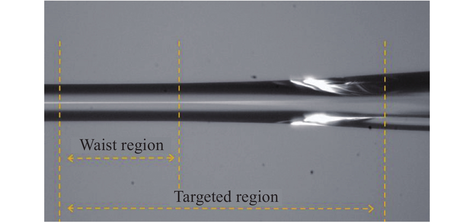
To solve this problem, an optimized fabrication process of the backward PSC is proposed, to minimize the influence of tapering on the signal fiber. The pump fibers are pre-tapered to reduce the diameter of them. The inner cladding of the output signal fiber is corroded by chemical etching to reduce its thickness and avoid the impact of tapering on the core. Then the pump fibers and signal fiber are twisted and fused to form a fiber bundle. After tapered slightly, the fiber bundle is cleaved at the waist region and spliced with the input signal fiber. In this fabrication process, only a few tapering is needed for the output fiber bundle of the backward combiner to match the input fiber. As shown in Fig.1, the influence of tapering operation on the core of the signal fiber is weakened, and the mode field mismatch of input and output fibers is alleviated. Rotating the fiber and changing the shooting angle of the camera, the shape of the white spot changed or disappeared in the picture. This may be caused by two possible reasons. One is the blocking of the two pre-tapered pump-fibers, another is the change of the roughness of the cladding during the chemical etching.

Figure 1. Output signal fiber of the backward combiner
Despite the development of the fabrication process, the fusing and tapering operations will still affect the core of the output signal fiber, to a certain degree, it may lead to the mode field mismatch in splicing. When the combiner is used in the forward-pumping structure, this mode field mismatch has a relatively small effect on the signal light transmission efficiency of the combiner. However, as shown in Fig. 2, when the combiner is used in the reverse-pumping structure, the core diameter mismatch has a greater negative influence, resulting in a negligible power loss of the signal light, and even cause overheating of devices.

Figure 2. Schematic diagram of the backward BPSC
Therefore, the enhancement of signal light transmission efficiency of the backward pump signal combiner is of great significance.
Optical fiber is a circular guided wave medium, and the signal light which propagates in the inner cladding and the core can be regarded as a special kind of electromagnetic wave. The exact solution of its electromagnetic vector can be derived from Maxwell's equations. For conventional double-clad fiber, the refractive index of the fiber core (n1) and the inner cladding (n2) are constant, The normalized frequency (V) of the double-cladding fiber can be defined as follows:
$$ {V}=\dfrac{2\mathrm{\pi }{a}}{\mathrm{\lambda }}\sqrt{{{n}}_{1}^{2}-{{n}}_{2}^{2}}=\dfrac{2\mathrm{\pi }{a}}{\mathrm{\lambda }}{N}{A} $$ (1) $ a $ is the radius of the core and$ \lambda $ represents the wavelength of the light and NA is the numerical aperture.It can be further deduced that for a double-cladding fiber, while the larger the V value is, the higher the energy concentration of signal light in the core of the signal fiber. Therefore, the value of V is only affected by the optical fiber's own parameters, when the wavelength remains unchanged.
In order to reduce the change of the core diameter and numerical aperture during the fabrication of the fiber bundle, we use an optimized chemical-etching and pre-tapering method. Compared with the original fabricating method, the time and quantity of the tapering process is shortened, and the change of core diameter and especially the NA is reduced. Based on this, subsequent simulation and experiments are carried out.
-
For the simulation of the power loss caused by the mode-field mismatch in single-mode fibers, a Gaussian beam is substituted for the signal light approximately [23]. While in the simulation of multi-mode fiber, it is generally believed that excitation of all modes are equal in the fiber, which means that the energy is evenly distributed in the fiber, so the geometry theory can be used in the simulation [24]. But in the pump signal combiner, we generally use the double-clad fiber with a relatively small normalized frequency (V) as the signal fiber. Only a few modes can be accommodated in the core of this signal fiber, mainly LP01 mode and LP11 mode, so it can neither be simply regarded as Gaussian beam nor use geometry theory for simulation.
-
Based on the premise that the roundness and refractive index of the signal fiber remains unchanged during the fabrication of the fiber bundle. The simulation model of transmission loss caused by mode field mismatch can be simplified to the core diameter mismatch between the waist and the input fiber.
According to the mode intensity distribution of the few-mode fiber, the simulation model is optimized to analyze the power loss caused by core diameter mismatch in the splicing. For few-mode double-clad fibers, most of its energy is concentrated in the core, and it can be assumed that the signal light propagates only in the core.
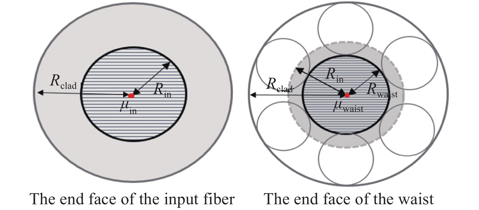
The end faces of the input fiber and the waist of the output fiber bundle are shown in Fig.3. The radius of the fiber bundle and the inner cladding of the input fiber are both set to Rclad. The core radius of the input fiber and the waist of the output fiber are Rin and Rwaist. At the end face of the input fiber, the proportion of the light intensity in the core to the light intensity in the range Rclad is set to
$ {\mathrm{\mu }}_{in} $ . At the end face of the waist, the proportion of the light intensity in the fiber core to the light intensity in the range Rin is set to${\mathrm{\mu }}_{{\rm{waist}}}$ . The core diameter matching rate is Rwaist/Rin, and the loss E of different modes caused by mode field mismatch can be expressed as:
Figure 3. Schematic diagram of the end face of the two fibers
$$ {E}={\mathrm{\mu }}_{{\rm{in}}}-{\mathrm{\mu }}_{{\rm{in}}}\times {\mathrm{\mu }}_{{\rm{waist}}}={\mathrm{\mu }}_{{\rm{in}}}\left(1-{\mathrm{\mu }}_{{\rm{waist}}}\right)\left({{R}}_{\mathrm{w}\mathrm{a}\mathrm{i}\mathrm{s}\mathrm{t}}\le {{R}}_{\mathrm{i}\mathrm{n}}\right) $$ (2) Taking the LP11 mode as an example, The schematic diagram of mode field mismatch between the input fiber and the waist region of the output fiber is shown in Fig. 4.

Figure 4. Schematic diagram of the LP11 mode coupling efficiency
The energy distribution of partial LP modes in the core of three kinds of fibers are shown in Tab.1 for further simulation.
Table 1. Energy distribution parameters of partial LP modes in double-clad fibers
Fiber type LP mode Proportion of energy in the core Proportion of energy 20/400 (NA = 0.065) 94.14% 95.24% 25/400 (NA = 0.065) LP01 mode 96.65% 96.65% 25/400 (NA = 0.11) 99.18% 99.18% 20/400 (NA = 0.065) 82.39% 86.93% 25/400 (NA = 0.065) LP11 mode 90.06% 90.06% 25/400 (NA = 0.11) 97.82% 97.82% 20/400 (NA = 0.065) — — 25/400 (NA = 0.065) LP02 mode 69.99% 69.99% 25/400 (NA = 0.11) 94.95% 94.95% 20/400 (NA = 0.065) — — 25/400 (NA = 0.065) LP21 mode 79.72% 79.72% 25/400 (NA = 0.11) 95.88% 95.88% As we can see from Tab.1 above, the higher order modes have a relatively lower energy ratio in the core of the fiber, which means the mode field mismatch in splicing has a greater impact on them. Among these three kinds of fibers, the 25/400 fiber with NA 0.11 has a higher proportion of the energy in the core, for its larger core diameter and NA.
-
In the manufacturing process of the common pump signal combiner, we mostly choose the same type of fiber as the input and output signal fiber. After the tapering process, the fiber bundle is cleaved at the waist region and then spliced with the input fiber. The ratio of the core diameter between the input fiber and the waist of the output signal fiber is expressed as
Dwaist/Dcore. Similar to the definition of mode field diameter in single-mode fibers, in the end-face of double-clad fibers, the mode field diameter of different LP modes can be defined as the maximum distance from the center to the point at which the light field strengths are reduced to 1/e2 of their maximum values.
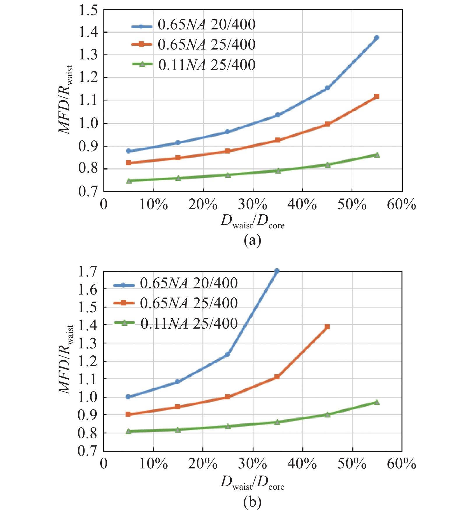
For different LP modes, we can characterize the concentration of energy distribution in the core by the ratio of their mode field diameter to the core diameter to a certain extent. In the waist region of the output fiber, the ratio μ can be expressed as:
$$ \mathrm{\mu }={M}{F}{D}/{{R}}_{\mathrm{w}\mathrm{a}\mathrm{i}\mathrm{s}\mathrm{t}} $$ (3) As we can see from the Fig.5, with the decrease of the core diameter in the waist region, the
$ \mathrm{\mu } $ value of the 0.11NA 25/400 fiber changed more slightly. It can be assumed that despite the reduction of the core diameter, the energy in the core is still relatively concentrated for the fiber has a large V value.
Figure 5. Concentration of energy distribution in the core (a) for the LP01 mode, (b) for the LP11 mode
According to the parameter in Tab. 1, the decline of the transmission efficiency caused by the core diameter mismatch in the signal fiber of the combiner is simulated. For the combiners made from two kinds of common LMA double cladding fibers (25/400 0.065NA & 20/400 0.065NA) and a large-NA fiber (25/400 0.11NA) are shown in Fig. 6(a) and (b).

Figure 6. Relationship between core diameter mismatch and transmission efficiency
The simulation results show that the output 25/400 fiber with a larger NA still has a higher normalized frequency V value and a higher core energy ratio, despite the core diameter of the waist becomes smaller. In case of the same degree of core diameter mismatch, the splicing loss of 25/400 fiber with NA 0.11 is obviously smaller compared with these two kinds of conventional double-clad fibers above.
-
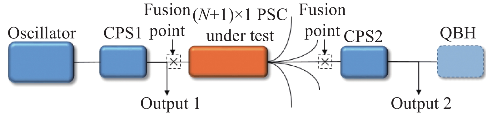
To verify the simulation result in section 3.2, a signal light transmission efficiency measurement system is established as shown in Fig.7.

Figure 7. Testing system of the backward combiner
The fiber laser oscillator, CPS1, combiner, CPS2, QBH are spliced in turn, the core diameters of the CPS1 and CPS2 are matched with the signal fiber of the combiner under test. The CPS1 can effectively strip the cladding light to avoid it from entering the combiner and affecting the test results. The CPS2 can strip the cladding light produced in the combiner, and avoid the influence of cladding light on the measurement of signal light output power.
The output power measured from the CPS1 and CPS2 are recorded as output 1 and output 2. By comparing these two sets of data, the transmission efficiency can be calculated. For further discussion, the beam quality test can be carried out after the CPS 2 is splicing with the output terminal QBH.
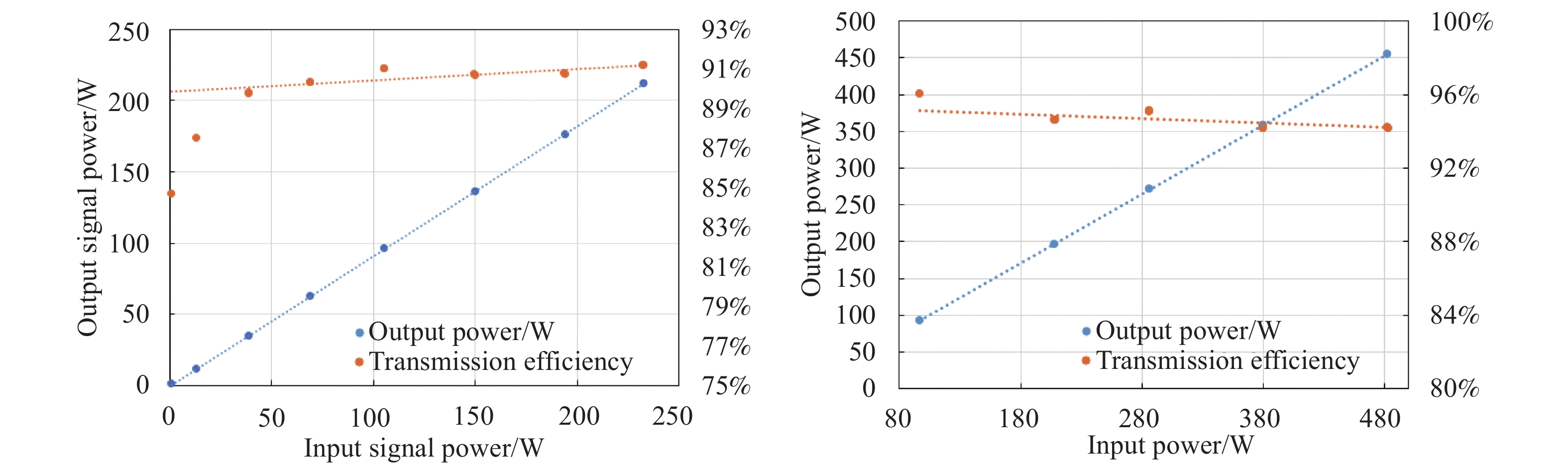
Two commercial (6+1)×1 backward PSCs made from 20/400 0.065NA fiber and 25/400 0.065NA fiber were tested. The signal light transmission efficiency of these two commercial PSCs are both higher than 95% when they are tested in a forward-pumping structure oscillator as a forward PSC, but when being tested in the reverse-pumping structure as a backward PSC the transmission efficiency decreased obviously.
Figure 8 (a) and 8 (b) show the test results of these two backward combiners. The light transmission efficiency of these two combiners are 91.14% and 94.1% respectively, and the power loss is too excessive to meet the requirement of kilowatt laser for the risk of overheating.

Figure 8. (a) 0.065NA 20/400 backward combiner, (b) 0.065NA 25/400 backward combiner
A backward (6+1)×1 pump-signal combiner is fabricated using the weak-tapering method mentioned in section 2, the type of pump fibers are 220/242-22FA and the signal fibers are both customized 25/400 fiber with NA of 0.11. The diameter of the pump fibers is reduced to 160 μm after pre-tapered, and the inner cladding of the output signal fiber is corroded to 160 μm by chemical etching approximately. Then with a slight tapering process, the fiber bundle can be matched with the input signal fiber for splicing.
Using the same test system and testing methods, the backward signal pump (6+1)×1 combiner made from customized 25/400 double-cladding fiber with a NA of 0.11 is tested, and the result is shown in Fig.9.
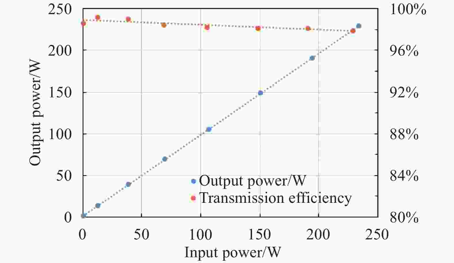
Figure 9. Signal transmission efficiency of the 0.11NA 25/400 backward combiner
The signal light transmission efficiency of this combiner is about 98%, obviously higher than those two combiners above. The infrared thermography of two 25/400 backward PSCs are as follow, as we can see from Fig.10, the temperature rise of the 0.11NA 25/400 backward combiners is much lower when the signal light input is about 500 W, and no device overheating occurs with a further increase of the input power, which meets the requirement of the kilowatt-level oscillator and MOPA amplifier.
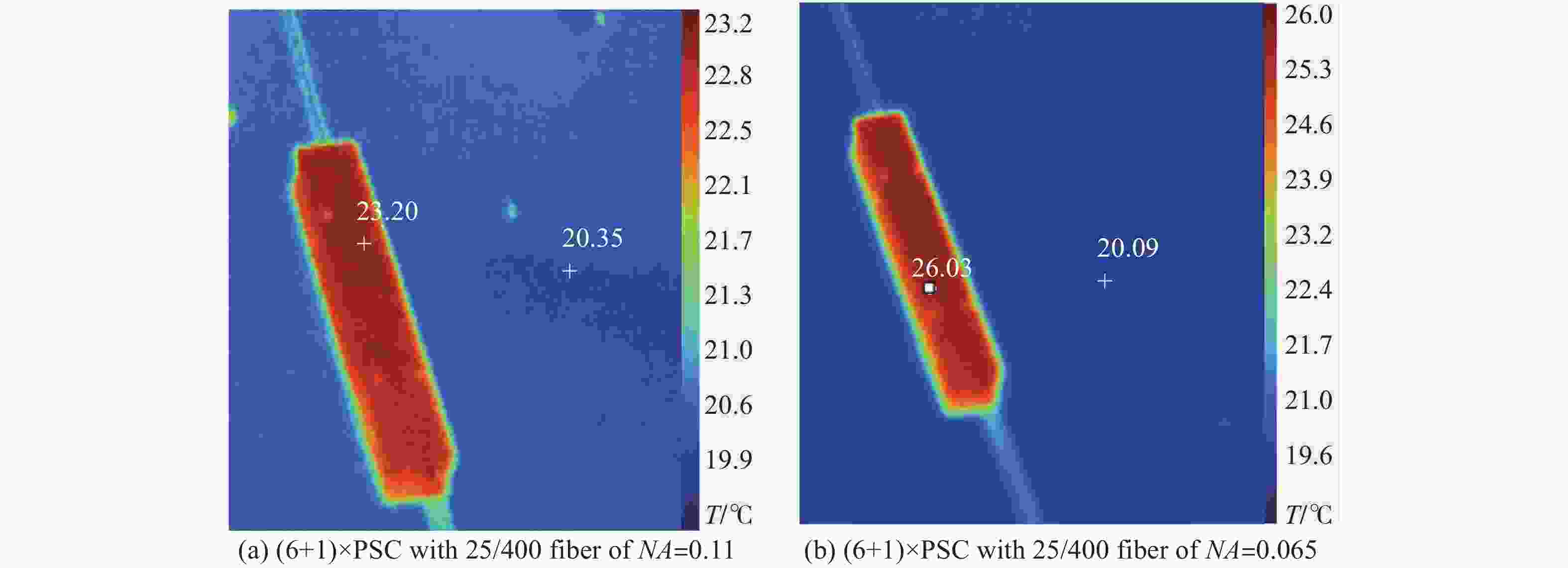
Figure 10. Infrared thermal images of two (6+1)×1 BPSCs
-
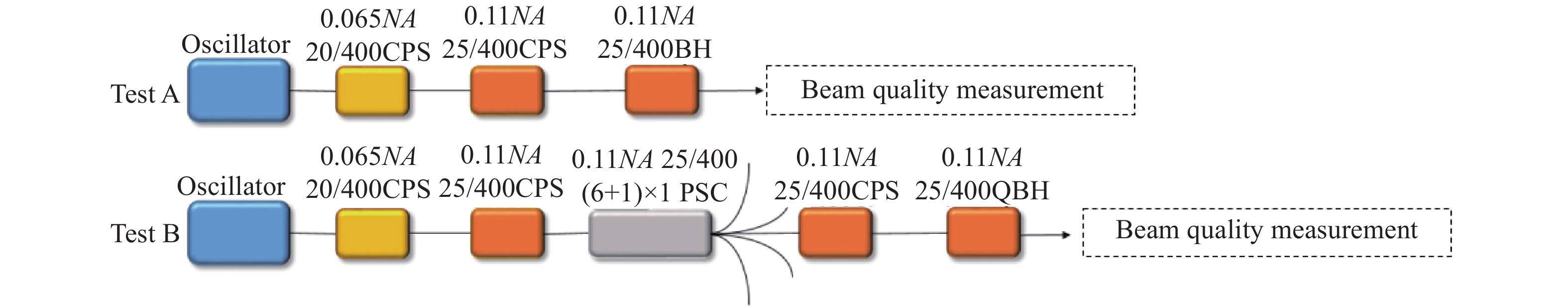
In order to analyze the beam quality deterioration that may occur in the large NA combiner, a test system is designed and built. Figure 11 is its schematic diagram.

Figure 11. Beam quality testing system for backward combiners
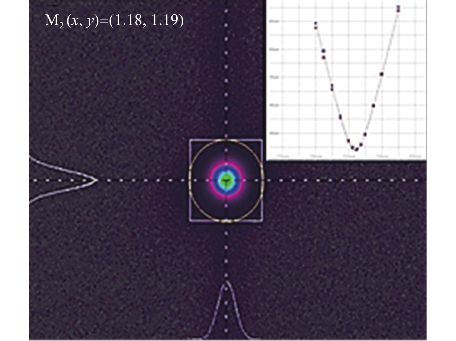
The output power of the oscillator is set to 200 W. The beam quality M2 of it is better than 1.2 when a conventional 20/400 QBH was used as the output terminal as shown in Fig.12.

Figure 12. Beam quality of the oscillator in the test system
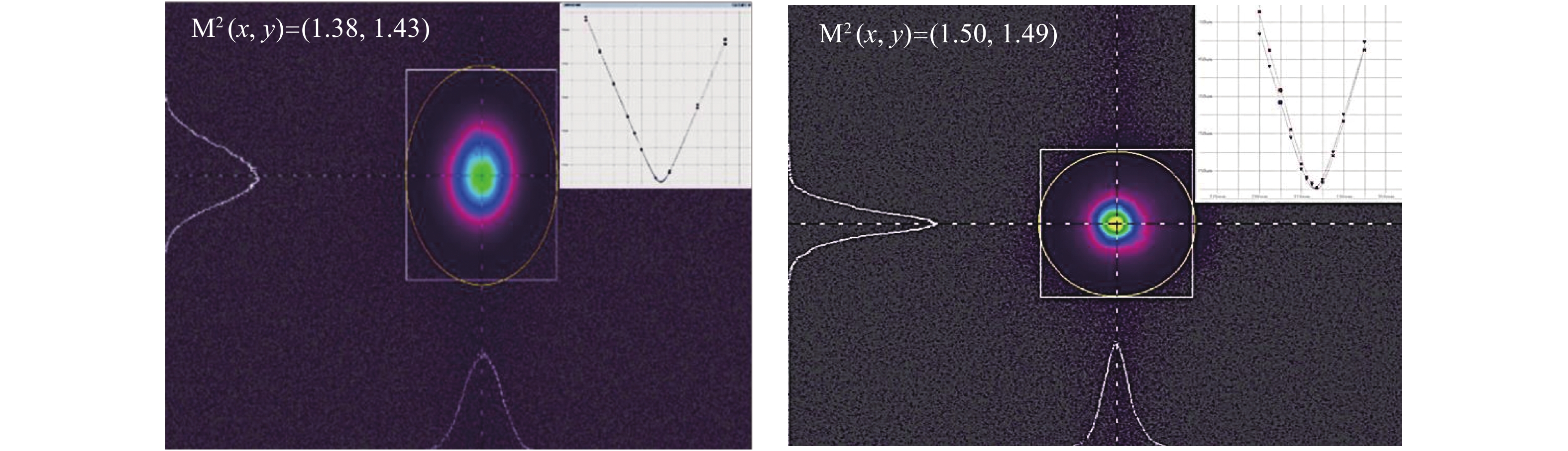
In test A, the conventional 0.065NA 20/400CPS of the oscillator is spliced to the CPS and QBH made from 0.11NA 25/400 double clad fibers. And the beam quality measured from this QBH is recorded as the control group of the experiment. Together with the backward (6+1)×1 PSC, another CPS is added into the test system to strip the cladding light, and the beam quality of the output signal light from the QBH is recorded in test B. By comparing the beam quality measured in these two tests above, the influence of this combiner on the beam quality can be analyzed approximately. The diagrams of the beam quality measured in test A and B are shown in Fig.13.

Figure 13. (a) Beam quality of test A, (b) beam quality of test B
The beam quality M2 measured in test A is approximately 1.4, after the 0.11NA (6+1)×1 PSC is set into the test system, the beam quality M2 deteriorated to 1.5 in test B. The experiment shows that, through the optimization of the manufacturing process, only mild tapering process is needed for the fiber bundle The decrease of the core diameter of the signal fiber is so small that the deterioration of beam quality caused by this backward combiner is acceptable.
Comparing the data of Fig. 12 and 13(a) we can find that because of the use of the 25/400 fiber with a large NA, the deterioration of the beam quality is obvious when the combiner is splicing with the 20/400 fiber of the oscillator. A MOPA amplifier made from conventional 25/400 fibers is fabricated in the further experiment in order to reduce the mode field mismatch, improve beam quality, and also to meet the demand of higher power laser output.
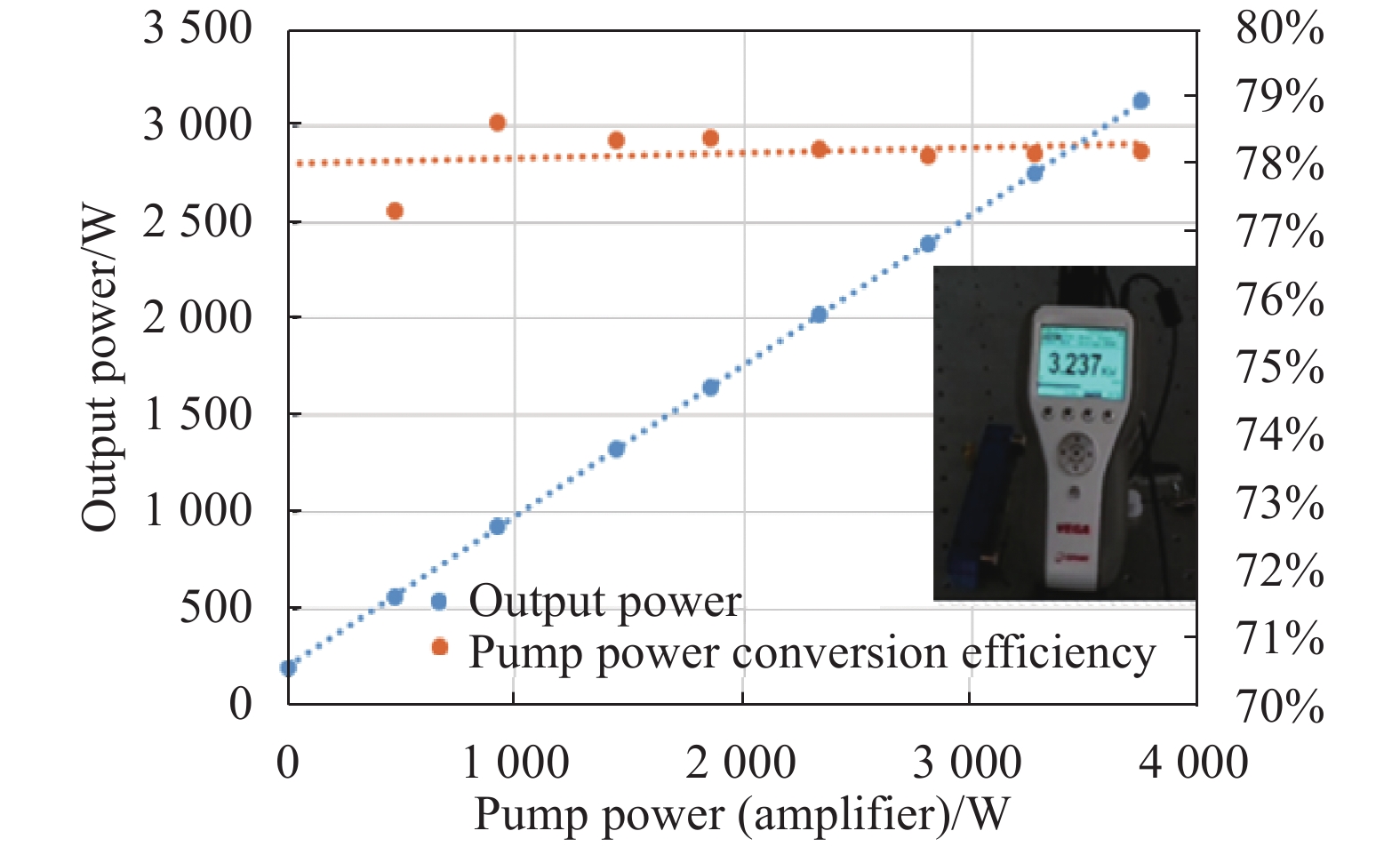
Accordingly, by using this (6+1)×1 backward PSC, a MOPA amplifier is set up and achieved a stable output of 3 kW. The output power curve is shown in Fig.14. The beam quality M2 is about 1.5 with the output of 1.5 kW as shown in Fig.15.

Figure 14. Output power of the 3 kW MOPA
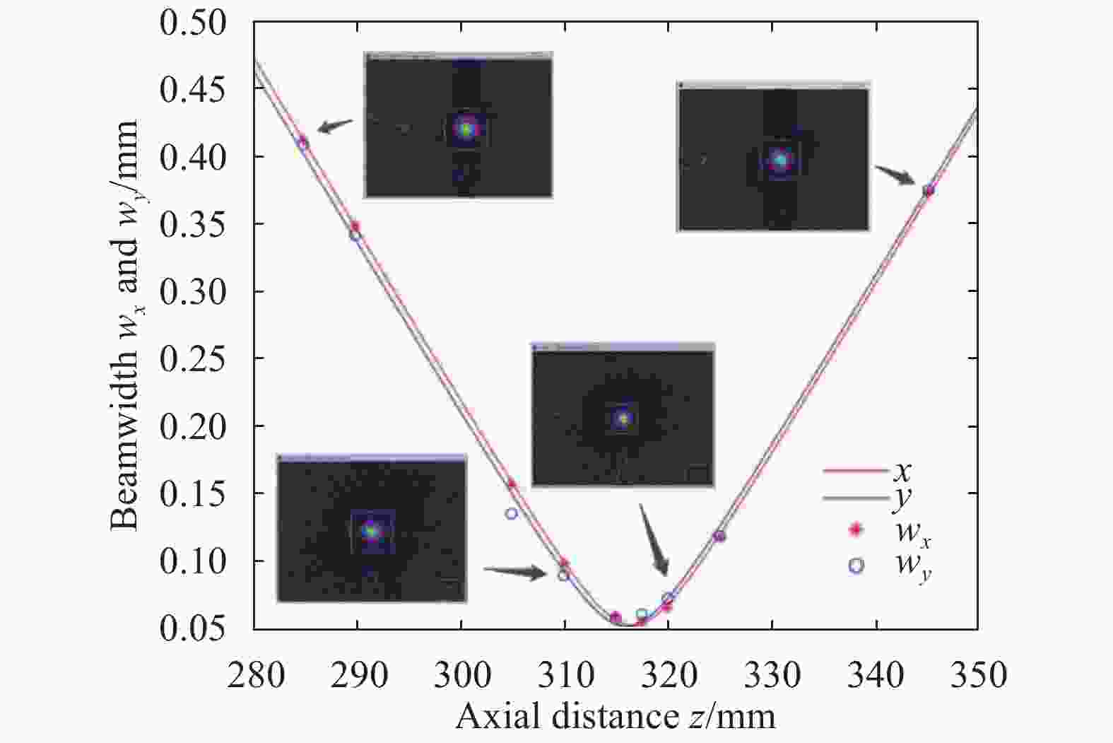
Figure 15. Beam quality of the MOPA
As the output signal power increased to 3 kW, the beam quality M2 of the amplifier decreased to 2.0. The reason for the further deterioration of beam quality may lie not only in this 25/400 0.11NA combiner but also in the subsequent devices which can accommodate a large number of modes. Due to the large NA and core diameter of the fibers used in these devices, the higher order modes which generated with the increase of power density can propagate steadily in the core and leads to the deterioration of beam quality after the further increase of the fiber power.
-
In order to reduce the power loss of signal light in BPSCs, a simulation model of the relationship between the signal light transmission efficiency and the signal fiber core match ratio Dwaist/Dcore is built. By using a new method we proposed in this paper and an optimized pre-tapering manufacturing process, the decrease of the core diameter of the signal fiber is relatively small that the transmission efficiency and the beam quality deterioration is acceptable.
Accordingly, a 0.11NA 25/400 (6+1) ×1 BPSC was made and it was used in a bi-directional pumping MOPA amplifier and reached a stable output of 3 kW. The (6+1)×1 BPSC has a good performance, high signal light transmission efficiency, small temperature rise and low water cooling burden under high power conditions. But at the same time, we also observed that, the signal fiber we used in the combiner and other subsequent devices has a relatively large normalized frequency (V). With the increase of the signal power, much more high order modes (HOMs) could be accommodated in the fiber. This will possibly result in the deterioration of beam quality. This problem deserves further consideration and strives, to find out a suitable signal fiber with optimum parameters to achieve the optimal configuration between a high transmission efficiency and a low degree beam quality deterioration.
Study on signal light transmission efficiency enhancement of backward pump-signal combiners in high-power fiber lasers
-
摘要: 在高功率光纤激光器反向泵浦信号合束器的制作过程中,经熔融拉锥后输出端的信号光纤纤芯变细,在与输入端信号光纤熔接时产生模场失配问题,造成反向泵浦信号合束器的信号光传输效率降低。针对这一问题,文中搭建了信号光纤熔接的芯径失配功率损耗模型,简析了光纤熔接时芯径失配与信号光功率损耗的关系。设计了一套泵浦信号反向合束器信号光功率损耗测试系统。提出了一种通过优化反向合束器信号光纤参数,提升反向泵浦信号合束器的信号光功率传输效率的方法,并通过预拉锥工艺,制作出一支25/400 (6+1)×1反向合束器,经测试,信号光传输效率优于98%,实验室使用该反向合束器搭建了一台MOPA结构光纤激光放大器,实现了3 kW稳定输出。Abstract: In the manufacturing process of the backward pump-signal combiner (BPSC) in high-power fiber lasers, the core diameter of the output signal fiber becomes thinner after being tapered, and the mode field mismatch occurs when splicing with the input signal fiber, which decreases the signal light transmission efficiency of BPSCs. To solve this problem, a simulation model was established to simplify the relationship between transmission efficiency and the mode field mismatch. A test system was built to measure the signal light transmission efficiency of backward pump-signal combiners. Finally, a method was proposed to enhance the signal power transmission efficiency of the BPSC through optimizing the parameters of its signal fiber. Accordingly, a (6+1)×1 BPSC using customized 25/400 double-cladding fibers was fabricated with a pre-tapering method, and its signal light transmission efficiency was better than 98% after being tested. Using this combiner, a bi-direction-pumping master oscillator power amplifier (MOPA) fiber laser system was built, achieving a stable output of 3 kW.
-
Figure 5. Concentration of energy distribution in the core (a) for the LP01 mode, (b) for the LP11 mode
Table 1. Energy distribution parameters of partial LP modes in double-clad fibers
Fiber type LP mode Proportion of energy in the core Proportion of energy 20/400 (NA = 0.065) 94.14% 95.24% 25/400 (NA = 0.065) LP01 mode 96.65% 96.65% 25/400 (NA = 0.11) 99.18% 99.18% 20/400 (NA = 0.065) 82.39% 86.93% 25/400 (NA = 0.065) LP11 mode 90.06% 90.06% 25/400 (NA = 0.11) 97.82% 97.82% 20/400 (NA = 0.065) — — 25/400 (NA = 0.065) LP02 mode 69.99% 69.99% 25/400 (NA = 0.11) 94.95% 94.95% 20/400 (NA = 0.065) — — 25/400 (NA = 0.065) LP21 mode 79.72% 79.72% 25/400 (NA = 0.11) 95.88% 95.88%  下载: 导出CSV
-
[1] IPG Photonics successfully tests the world's first 10-kilowatt single-mode production laser[EB/OL]. http://www.ipgphotonics.com, 2019. [2] Khitrov V, Minelly J D, Tumminelli R, et al. 3 kW single-mode direct diode-pumped fiber laser[C]//SPIE, 2014, 8961: 89610V. [3] Shima K, Ikoma S, Uchiyama K, et al. 5-kW single stage all-fiber Yb-doped single-mode fiber laser for materials processing[C]//SPIE, 2018, 10512: 105120C. [4] Yang B L, Shi C, Zhang H W, et al. Monolithic fiber laser oscillator with record high power [J]. Laser Physics Letters, 2018, 15(7): 75106. doi: 10.1088/1612-202X/aac19f [5] Bansal L, Headley C E. High efficiency pump signal combiner for high power fiber amplifier and laser applications: US patent, 20160139336[P]. 2016-05-19. [6] Lei Chenmin, Gu Yanran, Chen Zilun, et al. Development of high power all-fiber side-pumping combiner [J]. Optics and Precision Engineering, 2018, 26(7): 1561-1569. doi: 10.3788/OPE.20182607.1561 [7] Theeg T, Sayinc H, Neumann J, et al. Pump and signal combiner for bi-directional pumping of all-fiber lasers and amplifiers [J]. Optics Express, 2012, 20(27): 28125. doi: 10.1364/OE.20.028125 [8] Chen Zilun, Zhou Xuanfeng, Wang Zefeng, et al. Review of all-fiber signal combiner for high power fiber lasers (Invited) [J]. Infrared and Laser Engineering, 2018, 47(1): 0103005. [9] Li Libo, Lou Qihong, Zhou Jun, et al. High power single transverse mode operation of a tapered large-mode-area fiber laser [J]. Optics Communications, 2008, 281(4): 655-657. doi: 10.1016/j.optcom.2007.10.024 [10] Zheng J, Zhao W, Zhao B, et al. High pumping-power fiber combiner for double-cladding fiber lasers and amplifiers [J]. Optical Engineering, 2018, 57(3): 1. [11] Wang Biao, Pang Lu, Yi Yongqing, et al. 3.2 kW laser output by domestic 25/400 μm Yb-doped fiber [J]. Infrared and Laser Engineering, 2019, 48(7): 0706009. [12] Koška P, Baravets Y, Peterka P, et al. Mode-field adapter for tapered-fiber-bundle signal and pump combiners [J]. Applied Optics, 2015, 54(4): 751-756. doi: 10.1364/AO.54.000751 [13] Gonthier F, Martineau L, Seguin F, et al. Optical coupler comprising multimode fibers and method of making the same: US Patent, 7 046875[P]. 2006-5-16. [14] Yin S, Yan P, Gong M, et al. Fusion splicing of double-clad specialty fiber using active alignment technology [J]. Chinese Optics Letters, 2011, 9(2): 020601. doi: 10.3788/COL201109.020601 [15] Xiao Q, Yan P, Ren H, et al. Pump-signal combiner with large-core signal fiber feed-through for fiber lasers and amplifiers [J]. Applied Optics, 2013, 52(3): 409-414. doi: 10.1364/AO.52.000409 [16] Zimer H, Kozak M, Liem A. Fiber and fiber-optic components for high power fiber laser[C]//SPIE, 2011, 7914: 791414. [17] Xiao Q, Yan P, Wang Y, et al. Fused angle-polished multi-points side-pumping coupler for monolithic fiber lasers and amplifiers [J]. Optics Communications, 2012, 285(8): 2137-2143. doi: 10.1016/j.optcom.2012.01.001 [18] Yang Y, Lee J, Reichard K, et al. Fabrication and implementation of a multi-to-single mode converter based on a tapered multimode fiber [J]. Optics Communications, 2005, 249(1-3): 129-137. doi: 10.1016/j.optcom.2005.01.001 [19] Hideur A, Chartier T, Özkul C, et al. Dynamics and stabilization of a high power side-pumped Yb-doped double-clad fiber laser [J]. Optics Communications, 2000, 186(4): 311-317. [20] Xu J, Lu J, Kumar G, et al. A non-fused fiber coupler for side-pumping of double-clad fiber lasers [J]. Optics Communications, 2003, 220(4): 389-395. [21] Zhan H, Wang Y, Peng, et al. 2 kW (2+1) GT-wave fiber amplifier[J]. Laser Phys Lett, 2016, 13: 045103. [22] Jauregui C, Böhme S, Wenetiadis G, et al. Side-pump combiner for all-fiber monolithic fiber lasers and amplifiers [J]. Journal of the Optical Society of America B, 2010, 27(5): 1011-1015. doi: 10.1364/JOSAB.27.001011 [23] Marcuse D. Loss analysis of single-mode fiber splices [J]. Bell System Technical Journal, 1977, 56(5): 703-718. doi: 10.1002/j.1538-7305.1977.tb00534.x [24] Mettler S C. A general characterization of splice loss for multimode optical fibers [J]. Bell System Technical Journal, 2014, 58(10): 2163-2182. -

 点击查看大图
图(15) / 表(1)
计量
- 文章访问数: 366
- HTML全文浏览量: 58
- PDF下载量: 58
- 被引次数: 0


