


-
浮空器是一种主要依靠空气浮力留空的飞行器,其比重轻于空气。近年来,全球关于浮空器相关技术的研究迅速展开,并且相较于飞机等其他飞行器具有隐身性强,装载能力大,滞空时间久等优势,因而其在通信中继、科学探索、地质勘测等方面中的作用受到了越来越多研究人员的重视[1-2]。对高空环境作业的飞行器蒙皮结构进行应变监测是使其正常可靠工作的重要保障[3-4]。
光纤布拉格光栅(fiber Bragg grating,FBG)传感器是一种以光纤为介质,集信息传输与传感于一体,根据光信号变化测量结构应变的新型传感器[5]。与传统结构应变传感器相比,光纤光栅传感器具有柔性好、响应速度快、灵敏度高和抗电磁干扰等优势,并且利用光纤传感网络可实现多测点多路的传感测量[6-7]。利用光纤传感技术可以解决浮空器空中飞行过程中气囊应变监测问题,可为准确获取复杂空中环境下浮空器蒙皮结构飞行状态参数,进而实现高可靠性和高安全性的飞行控制提供关键技术支撑。基于光纤光栅应变传感优势,国内外对于利用光纤光栅传感器对基体结构进行应变监测开展了很多研究,结构应变传递效率也成为光纤光栅应变监测领域的重要研究方向。目前关于表面粘贴式光纤光栅传感器应变传递效率的研究,主要包括:应变传感模型及传递机理的研究分析,传感结构灵敏度实验研究以及提高传递效率的不同封装方式。
对于应变传感模型及传递机理,Zhang[8]等针对表面结合的蓝宝石衍生的光纤光栅传感器,提出了一种将纤芯和包层分离的应变传递改进模型,分析了纤芯参数对应变的影响。Falcetelli[9]等建立多层结构应变传递模型,通过实验和数值验证了传感结构的粘合末端存在应变。Sun[10]等基于剪切之后理论,研究了光纤光栅传感器应变传递机理,验证了FBG传感器应用于超大应变监测的可行性。Chen[11]等建立了从基体到光纤的平均应变传递模型,与现有模型相比提高了测量精度。Liang[12]等考虑了胶层的线性粘弹性效应,建立了表面粘结光纤光栅剪切应变传递的力学分析模型,理论分析了瞬时应变传递和准静态应变传递的影响因素。对于传感结构的灵敏度,Motwani[13]等实验分析了不同粘贴层对传感结构灵敏度的影响。Fisser[14]等提出一种基于FBG温度特性校准应变传递系数及灵敏度的方法。Wang[15]等基于四层光纤传感结构,实验分析了具有不同热膨胀系数的基底结构对应变传递的影响。对于不同的封装方式,Kim[16]等理论分析了金属涂层的力学参数和几何参数对封装的FBG传感器传递效率的影响。Zhang[17]等通过实验比较了金属封装和胶接封装FBG传感器的应变传递特性。曾鹏[18]等实验分析胶接封装中胶粘剂参数对应变传递的影响。
国内外学者在对表面粘贴式FBG传感器的应变传递的研究上,已经取得了一定成果。但是,在浮空器柔性复合蒙皮应变光纤监测方面,由于蒙皮结构为层合式柔性复合材料,不同于传统刚性材料,其各层材料间相互耦合影响,对其应变传递效率分析的研究尚少,需要研究高应变传递效率的方法。针对这一问题,文中通过建立“光纤光栅—粘贴层—蒙皮结构”三层应变传递模型,得到了应变传递效率关系,研究分析了浮空器柔性复合蒙皮用光纤光栅传感器应变传递特性及相关影响因素。
-
根据浮空器柔性蒙皮形变测量需求及光纤光栅在蒙皮结构表面粘贴后形成的横截面,建立如图1所示“光纤光栅—粘接层—蒙皮结构”三层无涂覆层光纤光栅传感结构。其中粘接层长度略大于光纤光栅的长度,2Lf,D,hc分别为粘接层长度、宽度及光栅上表面与粘接层顶部距离。

图 1 无涂覆层FBG表贴结构
Figure 1. Surface bonded structure of uncoated FBG
其中,浮空器蒙皮为层合式柔性复合材料,一般由防护层、气密层、承力层以及粘接层4种主要层组成,各层材料之间相互耦合影响,从而满足浮空器各项性能要求[19]。由于浮空器蒙皮复合结构各层均受到均匀的轴向外力作用而产生轴向应变,且由蒙皮外表面应变通过粘接层传递给光纤,因此,为便于模型分析,对模型提出以下假设[20]:(1)柔性复合蒙皮看作整体结构分析;(2)光纤、粘接层和柔性复合蒙皮各层均为线弹性材料;(3)传感模型三层结构间结合紧密;(4)光纤光栅粘贴后对蒙皮结构无影响。无涂覆层FBG表贴结构受力情况如图2所示。其中f,c,m分别表示光纤、粘接层和蒙皮基底相关的物理量。

图 2 三层结构受力传递示意图
Figure 2. Schematic diagram of force transfer of three-layer structure
在x方向上各层结构受力平衡,对光栅微元段进行受力分析可得:
$$\pi r_f^2{\sigma _f} - \pi r_f^2({\sigma _f} + {\rm d}{\sigma _f}) = 2\pi {r_f}\tau (x,{r_f}){\rm d}x$$ (1) 对粘接层结构进行受力分析可得:
$$\begin{array}{*{20}{l}} {[({D_c}({r_c} + {h_c} + {r_f}) - \pi r_f^2)]{\sigma _c} - }\\ {[({D_c}({r_c} + {h_c} + {r_f}) - \pi r_f^2)]({\sigma _c} + {\rm d}{\sigma _c}) = }\\ {{D_c}{\rm d}x\tau (x,{r_c}) - 2\pi {r_f}{\rm d}x\tau (x,{r_f})} \end{array} $$ (2) 取蒙皮结构单位微元并进行受力分析,得:
$$\begin{array}{l} {D_c}({r_m} - {r_c}){\sigma _m} - {D_c}({r_m} - {r_c})({\sigma _m} + {\rm d}{\sigma _m}) = \\ {D_c}\tau (x,{r_m}){\rm d}x - {D_c}\tau (x,{r_c}){\rm d}x \\ \end{array} $$ (3) 当
$r \geqslant {r_m}$ 时,处于蒙皮基体之外,剪应力为0。因此,$$\tau (x,{r_m}) = \tau (x,{r_c}) - ({r_m} - {r_c})\frac{{{\rm d}{\sigma _m}}}{{{\rm d}x}} = 0$$ (6) 光栅与粘接层,粘贴层与蒙皮基体均紧密连接,不发生相对滑移,并同步变形,则应变变化率相等。根据材料力学应力应变
$\sigma = E\varepsilon $ ,且光栅径向变形很小,可忽略泊松效应及径向位移。则:$$\tau \left( {x,r} \right) = G\gamma (x,r) \cong G\frac{{{\rm d}u}}{{{\rm d}r}}$$ (7) 因此,在区间
$[{r_f},{r_c}]$ 内剪应力为:$$\tau \left( {x,r} \right) = - \frac{{[{D_c}(r + {r_f} + {h_c}){E_c} + \pi {r_f}^2{E_f}]{\rm d}{\varepsilon _f}}}{{{D_c}{\rm d}x}}$$ (8) 在区间
$[{r_c},{r_m}]$ 内剪应力为:$$\tau (x,r) = \left(\frac{{r - {r_c}}}{{{r_m} - {r_c}}} - 1\right)\Bigg[({r_c} + {r_f} + {h_c}){E_c} + \frac{{\pi r_f^2{E_f}}}{{{D_c}}}\Bigg]\frac{{{\rm d}{\varepsilon _f}}}{{{\rm d}x}}$$ (9) 将公式(8)和(9)分别在区间
$[{r_f},{r_c}]$ 和$[{r_c},{r_m}]$ 上积分后相加,可得:$$\begin{array}{l} {u_m} - {u_f} = - {E_f}\left[\dfrac{{\pi r_f^2({r_c} - {r_f})}}{{{G_c}{D_c}}} - \dfrac{{\pi r_f^2({r_c} - {r_m})}}{{2{G_m}{D_c}}}\right]\dfrac{{{\rm d}{\varepsilon _f}}}{{{\rm d}x}} - \\ {E_c}\left[\dfrac{{(2{h_c} + {r_c} + 3{r_f})({r_c} - {r_f})}}{{2{G_c}}} - \dfrac{{({h_c} + {r_c} + {r_f})({r_c} - {r_m})}}{{2{G_m}}}\right]\dfrac{{{\rm {\rm d}}{\varepsilon _f}}}{{{\rm d}x}} \\ \end{array} $$ (10) 化简公式(10)可得:
$${u_m} - {u_f} = - \frac{1}{{{k^2}}}\frac{{{\rm d}{\varepsilon _f}}}{{{\rm d}x}}$$ (11) 其中k表示应变传递滞后系数,则:
$$\begin{array}{l} \dfrac{1}{{{k^2}}} = {E_c}\left[\dfrac{{(2{h_c} + {r_c} + 3{r_f})({r_c} - {r_f})}}{{2{G_c}}} - \dfrac{{({h_c} + {r_c} + {r_f})({r_c} - {r_m})}}{{2{G_m}}}\right] + \\ {E_f}\left[\dfrac{{\pi r_f^2({r_c} - {r_f})}}{{{G_c}{D_c}}} - \dfrac{{\pi r_f^2({r_c} - {r_m})}}{{2{G_m}{D_c}}}\right] \\ \end{array} $$ (12) 对x进行求导,可得光纤光栅应变在轴向分布和蒙皮结构应变关系控制方程:
$$\frac{{{{\rm d}^2}{\varepsilon _f}(x)}}{{{\rm d}{x^2}}} - {k^2}{\varepsilon _f}(x) = - {k^2}{\varepsilon _m}$$ (13) 上式通解为
${\varepsilon _f}(x) = {C_1}{{\rm e}^{kx}} + {C_2}{{\rm e}^{ - kx}} + {\varepsilon _m}$ ,假设FBG端部存在边界条件,为自由端,应变传递为0。即,${\varepsilon _f}({L_f}) = {\varepsilon _f}( - {L_f}) = 0$ 。所以FBG轴线方向应变为:$${\varepsilon _f}(x) = \left(1 - \frac{{\cosh (kx)}}{{\cosh (k{L_f})}}\right){\varepsilon _m}$$ (14) 光纤光栅粘接层各点应变传递率为:
$$\phi (x) = \frac{{{\varepsilon _f}(x)}}{{{\varepsilon _m}}} = 1 - \frac{{\cosh (kx)}}{{\cosh (k{L_f})}}$$ (15) 在蒙皮实际应变测量中为平均应变,则平均应变传递率为:
$$\overline \phi (x) = \dfrac{{2\displaystyle\int_0^{{L_f}} {{\varepsilon _f}(x){\rm d}x} }}{{2{L_f}{\varepsilon _m}}} = 1 - \frac{{\sinh (k{L_f})}}{{k{L_f}\cosh (k{L_f})}}$$ (16) -
为了验证该应变传感结构传递关系的准确性,建立三层传感结构的有限元模型对传感器进行仿真分析,各层结构几何参数分别为:光纤光栅
$10 \times $ $ \phi 0.125\;\rm mm$ ;粘接层$10\;\rm mm \times 4\;\rm mm \times 1\;\rm mm$ ,其中上粘接层厚度,即${h_c}$ 为$0.437\;5\;\rm mm$ ,下粘贴层厚度,即${r_c}$ 取值为$0.5\;\rm mm$ ;浮空器蒙皮基体$10\;\rm mm \times 5 \;\rm mm\times 2\;\rm mm$ 。并通过仿真及数值计算分析FBG中心线处的应变值与蒙皮产生应变值,得到沿FBG轴向不同位置处应变传递率变化关系。如表1所示为传感结构各层材料参数。表 1 各层结构材料参数
Table 1. Material parameters of each layer structure
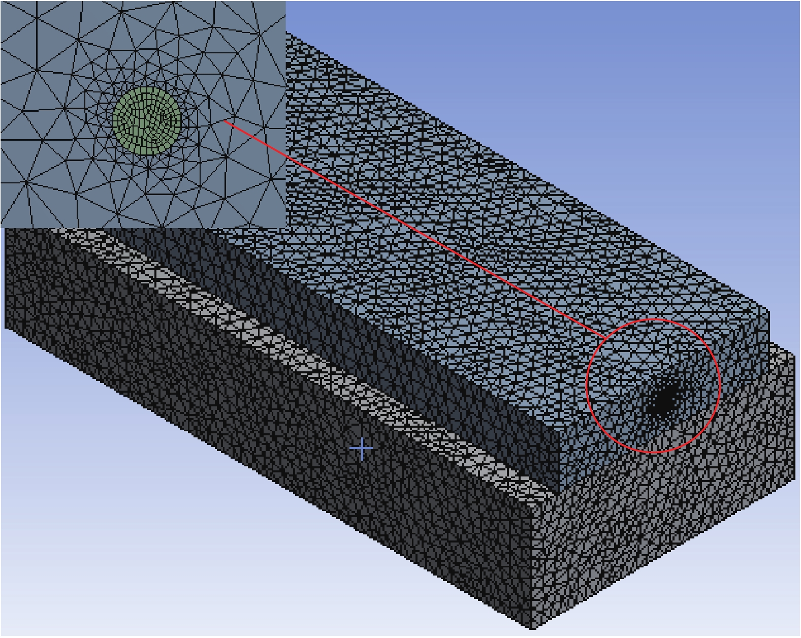
FBG Adhesive layer Skin structure Elastic modulus/Pa $7.2 \times {10^{10}}$ $3.0 \times {10^9}$ $3.59 \times {10^9}$ Poisson's ratio 0.17 0.35 0.3 在实际计算过程中,根据浮空器蒙皮用FBG应变传感器的使用情况,假设各层结构之间均为理想界面,并且不产生相对滑移的情况。因此,建立的三层FBG传感结构有限元模型如图3所示。

图 3 传感结构有限元模型
Figure 3. Finite element model of sensing structure
通过对该三层FBG传感结构进行有限元分析,可得到在浮空器蒙皮实际测量过程中FBG轴向不同位置处应变传递效率变化关系。采用控制变量法,仅改变光纤光栅三层传感结构的粘贴长度2L,分别取粘贴长度2L为10 mm、20 mm、30 mm及40 mm,并建立相应的有限元分析模型,对其进行应变传递理论求解和有限元仿真计算。如图4所示分别为在不同传感器标距长度下,光纤沿轴向位置应变传递率变化关系的理论曲线和有限元仿真曲线。

图 4 光纤轴向应变沿长度分布
Figure 4. Fiber axial strain distribution along the length
由图4得出,FBG三层传感结构光纤纤芯在不同标距长度下,其应变传递沿轴向位置具有相同的变化趋势。该结构下光纤光栅传感器应变传递率变化曲线呈对称结构,在光栅中间位置处应变传递率最大,并且随着传感器标距长度的增加而增大,由图4(a)和(b)均可得,传感器标距长度为20 mm、30 mm和40 mm时,其中间位置处的理论值及仿真值的最大传递效率较为接近,且最大都达到了94%以上。由光纤中间位置向两端,其应变传递效率逐渐减小,在光纤传感器端点位置处其应变传递率最小并趋近于0。分别对比4种不同标距长度传感器的理论值和仿真结果得出,4种FBG传感器的理论曲线和仿真结果曲线均具有较高的相似度,证明了该理论分析的正确性。
图5为不同传感器标距长度下,光纤沿轴向位置应变传递率的理论值与有限元仿真值之间的误差曲线。分析得出,4种不同标距长度的传感器理论与仿真间误差分布的趋势是相同的。同一标距长度的FBG传感器,在中间位置处的应变传递率非常接近,因此,其中间区域处的误差较小,且4种传感结构中间区域处相对误差均在5%以内。但在该传感结构两端具有较大的误差,其原因是由于在应变传递理论分析过程中假设光栅与粘接层相接端部为自由端,无应力传递,并且有限元计算结果也为近似解[21],因此在传感器两端处误差较大。
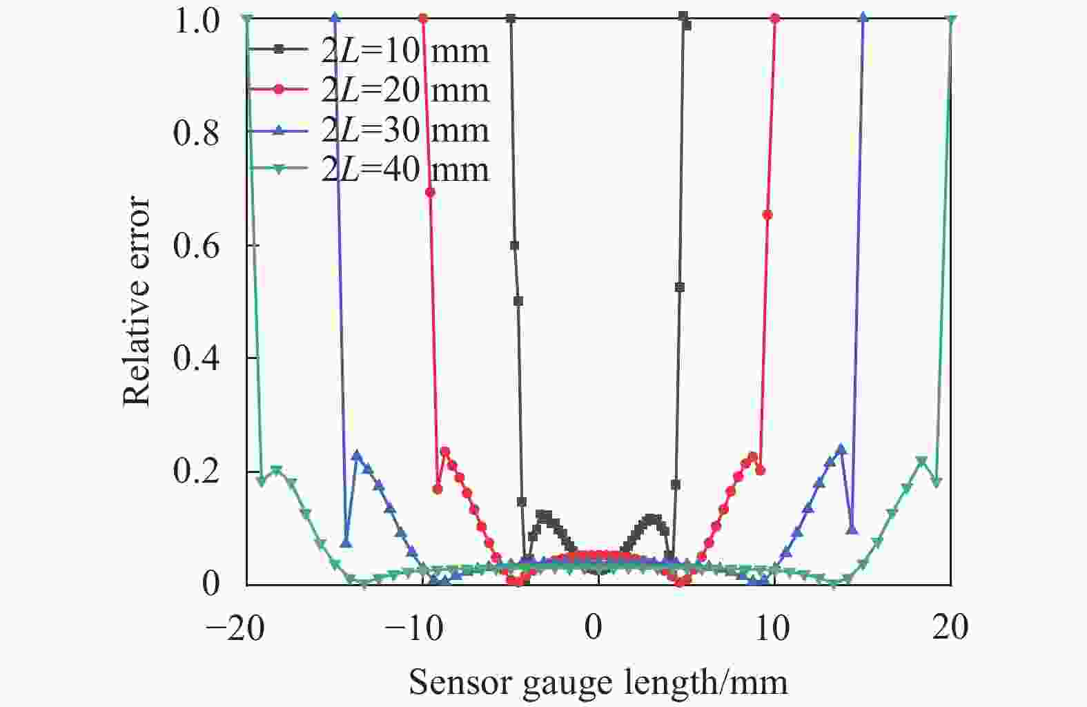
图 5 理论值与仿真值之间误差曲线
Figure 5. Error curves between theoretical value and simulated value
图6为4种不同标距长度下FBG传感器理论和仿真的最大应变传递率与平均应变传递率的结果对比,数据表明,理论与仿真的最大应变传递效率随着传感器标距长度的变化,其结果较为相近,并且当标距长度大于15 mm时,理论值始终大于仿真值。对比平均应变传递率,三者具有相同的变化趋势,但平均应变传递效率相较于理论与仿真结果最大值有一定差距,随着传感器标距长度的增加,三者差距逐渐缩小。在表面粘贴式FBG传感器实际应用中,传感器所测得应变结果为光纤光栅所粘贴的蒙皮长度范围内的平均值,常以平均应变传递率来表征浮空器蒙皮结构的真实应变状态,因此可根据需求适当增加标距长度。

图 6 不同标距长度FBG传感器最大应变传递率与平均应变传递率结果对比
Figure 6. Comparison of results of maximum strain transfer rate and average strain transfer rate of FBG sensors with different gauge lengths
-
通过对浮空器柔性复合蒙皮用表贴式光纤光栅传感器应变传递率分析,可得蒙皮所受应力在各层结构之间以剪切应力的方式进行传递,粘贴层作为该三层应变传感结构的中间层,其相关物理参数对应变传递率有着重要的影响。为了得到浮空器蒙皮用光纤光栅传感器的最优结构参数,对粘贴层参数进行仿真分析。如表2所示为粘贴层相关参数取值情况。
表 2 粘贴层结构参数
Table 2. Structure parameters of pasted layer
Parameters Value range Half length of adhesive layer/mm 5-20 Width of adhesive layer/mm 0-10 Thickness of upper adhesive layer/mm 0-1 Thickness of lower adhesive layer /mm 0-1 Elastic modulus/GPa 0-1 Poisson's ratio 0.2-0.5 当粘贴层宽度Da在[4 mm 10 mm]取值区间变化时,半粘贴长度L分别取5 m、10 mm、15 mm和20 mm时,该浮空器蒙皮用FBG三层传感结构平均应变传递率变化曲线如图7所示。

图 7 粘贴层宽度Da和长度L对平均应变传递率的影响
Figure 7. Effect of adhesive layer width Da and length L on average strain transfer rate
由图7可得,平均应变传递率随着粘贴层宽度的增加逐渐增大,当粘贴层宽度达到3 mm时,增加趋势平缓并逐渐接近饱和。当粘贴宽度相同时,对比4条不同粘贴长度情况下的曲线可得,随着粘贴长度的增大,平均应变传递率随之增加。因此,根据4条平均应变传递率变化曲线可得,浮空器蒙皮用FBG传感器粘贴层宽度可取6 mm,半粘贴长度可取20 mm。
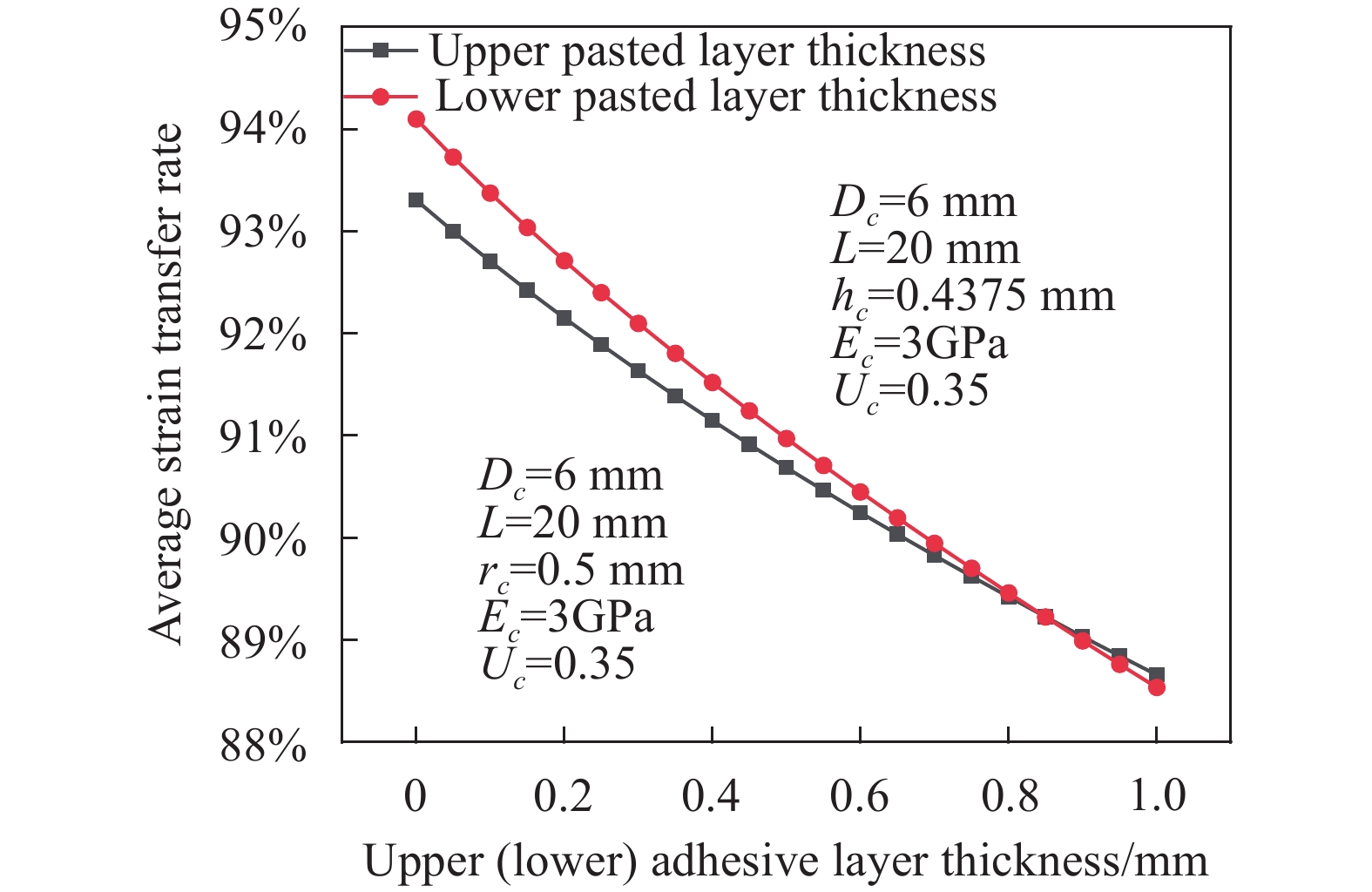
图8为上粘贴层厚度
${h_c}$ 和下粘贴层厚度${r_c}$ 均在0~1 mm之间变化时,平均应变传递率的变化曲线。由图可得,随着上或下粘贴层厚度的增大,平均应变传递率均呈近似线性减小,且二者对平均应变传递率的影响程度相似。因此,为保证较高应变传递率,应缩小上和下粘贴层厚度。
图 8 上(下)粘贴层厚度对平均应变传递率的影响
Figure 8. Effect of the thickness of the upper (lower) adhesive layer on the average strain transfer rate
图9为粘贴层弹性模量对平均应变传递率的影响。数据表明,当粘贴层弹性模量非常小时,其对平均应变传递率有着明显影响。随着粘贴层弹性模量的增大至0.5 GPa左右时,FBG传感器平均应变传递效率逐渐减小,但减小趋势较为平缓。应根据实际工程需要选择相应的粘贴剂,从而达到理想的平均应变传递率。环氧树脂胶常温固化,对多种溶剂具有优异抵抗性,并且弹性模量一般小于0.5 GPa[22]。因此,环氧树脂胶可作为浮空器蒙皮用的FBG传感器的粘贴胶剂。

图 9 粘贴层弹性模量对平均应变传递率的影响
Figure 9. Effect of elastic modulus of adhesive layer on the average strain transfer rate
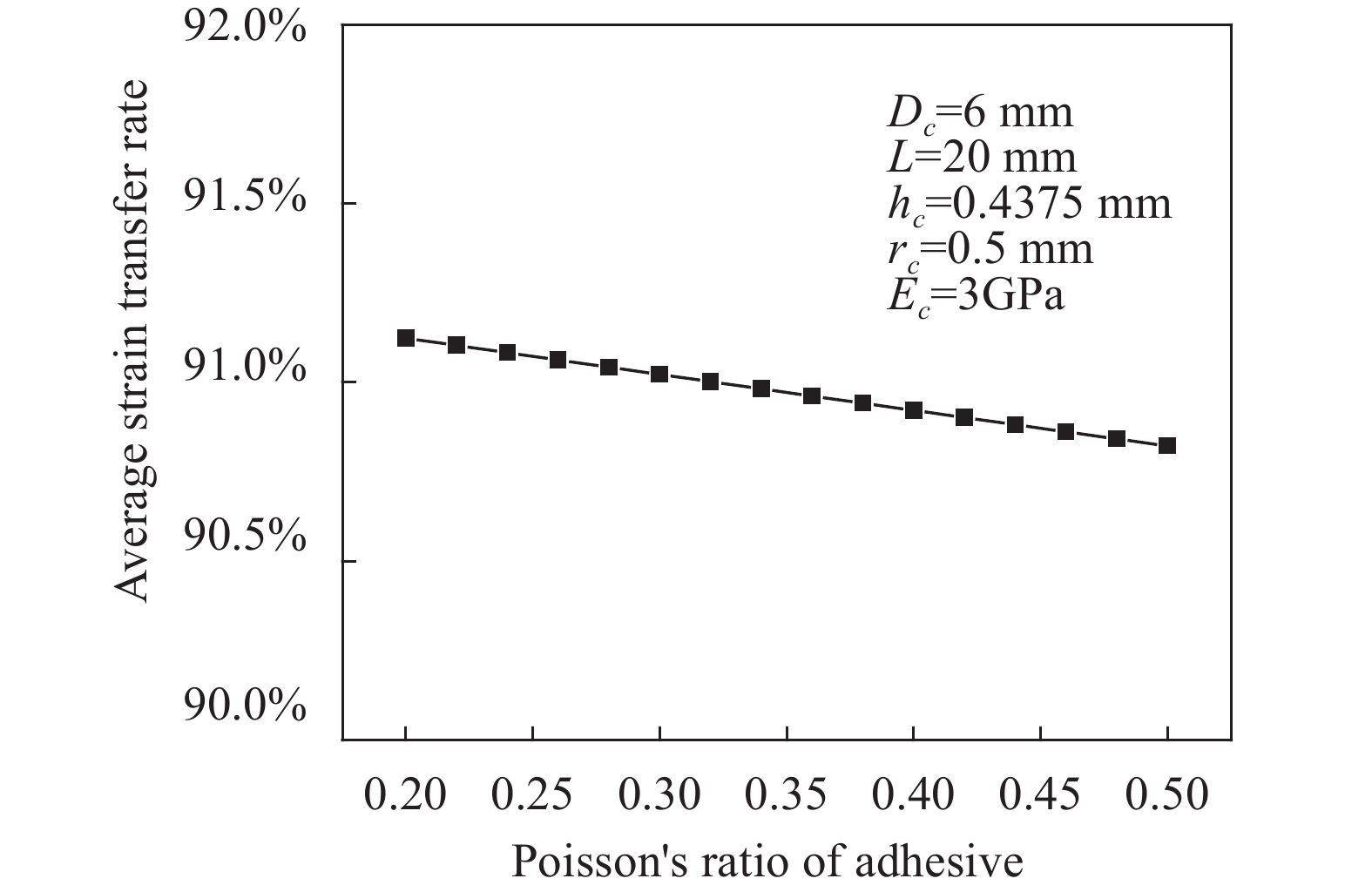
图10为粘贴层泊松比对平均应变传递率的影响。分析可得,当泊松比在0.2~0.5之间变化时,平均应变传递率呈近似线性减小,但减小幅度很小。在实际应用中,由于粘贴层泊松比变化范围较小,可忽略其影响。

图 10 粘贴层泊松比对平均应变传递率的影响
Figure 10. Effect of Poisson’s ratio of adhesive layer on average strain transfer rate
-
浮空器蒙皮材料的主要结构为柔性织物的复合材料,实验室搭建的浮空器应变监测系统蒙皮结构为210D牛津复合布,其抗拉强度
$ \geqslant $ 800 N,具有良好的加工性能和气密性。由于蒙皮材料为层压合成的织物复合材料,在对其0~90°不同偏轴方向进行拉伸时,不同的偏轴拉伸蒙皮材料具有不同的弹性模量[23]。因此,对蒙皮结构弹性模量的变化对平均应变传递率的影响进行分析,可得不同拉伸方向下蒙皮应变传递变化规律。如表3所示为蒙皮结构参数的取值范围[24]。表 3 蒙皮结构参数
Table 3. Skin structure parameters
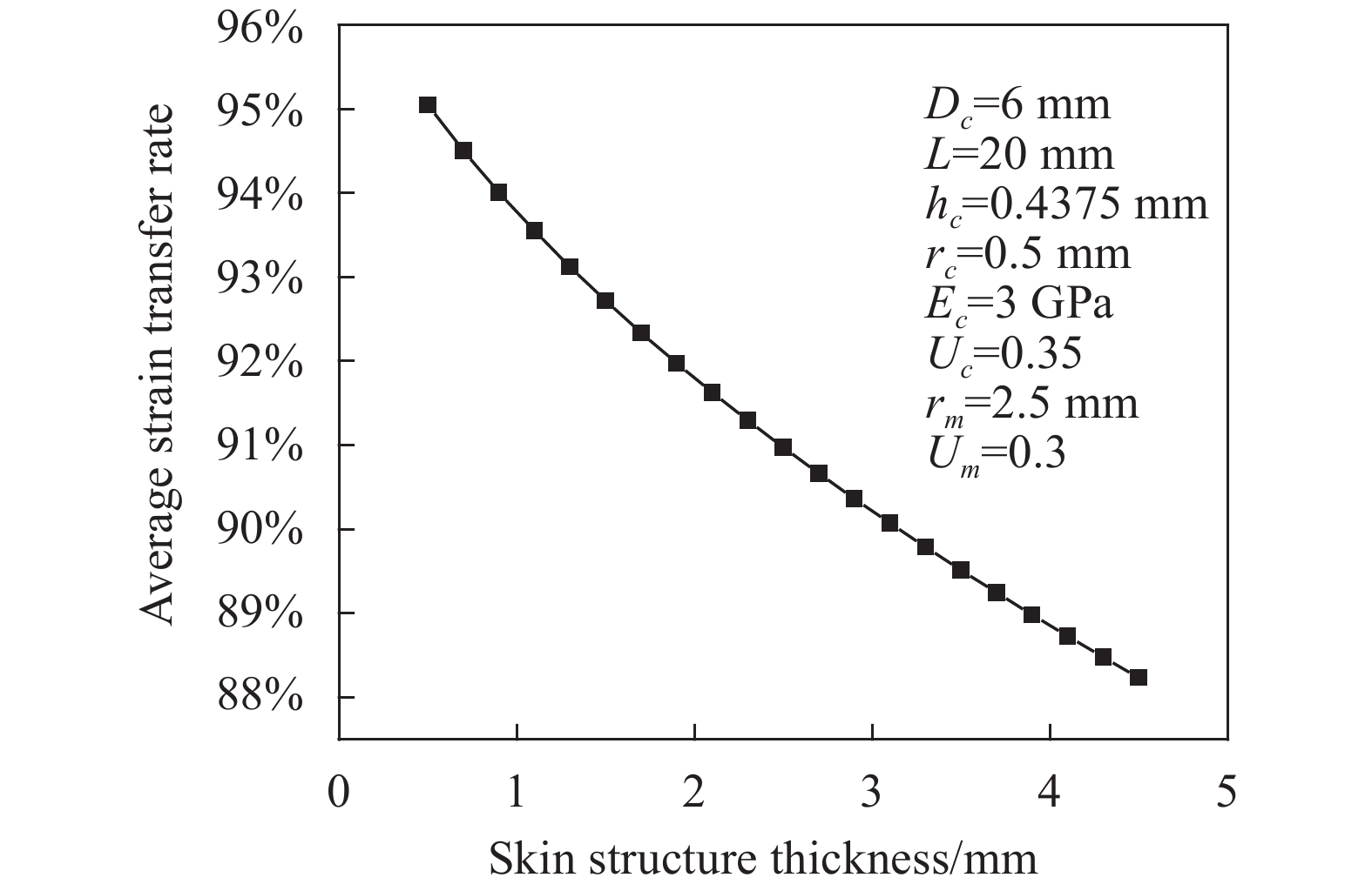
Structural parameters Value range Elastic modulus/Pa 1.75-3.59 Skin thickness/mm 0.5-4.5 当蒙皮结构弹性模量在1.75~3.59 GPa之间取值,其结构厚度于0.5~4.5 mm之间取值时,平均应变传递效率变化曲线分别如图11和12所示。

图 11 蒙皮结构弹性模量对平均应变传递率的影响
Figure 11. Effect of elastic modulus of skin structure on average strain transmission rate

图 12 蒙皮结构厚度对平均应变传递率的影响
Figure 12. Effect of skin structure thickness on average strain transfer rate
由图11分析可得,当蒙皮结构弹性模量增大时,平均应变传递效率随之增加,但随着弹性模量的持续增大,其平均应变传递率增大趋势变平缓。由图12分析可得,蒙皮结构厚度越大,其平均应变传递率越小。因此,在进行浮空器蒙皮应变测量分析过程中,应将蒙皮结构参数考虑在内,从而提高应变测量精度。
-
由建立的“光纤光栅—粘贴层—蒙皮结构”三层传感模型得出,影响FBG传感器应变传递效率的因素有:光纤光栅、粘贴层和浮空器蒙皮结构的弹性模量和泊松比;粘贴层的长度、宽度和粘贴厚度;蒙皮结构厚度。在各个相关影响因素确定的情况下,该FBG传感结构中心处具有较大应变传递率,且由中间位置向两端,其应变传递效率逐渐减小。在相同传感位置处,选取弹性模量满足要求的常温固化环氧树脂胶,并减小粘贴层厚度,适当增加粘贴宽度和长度,可增大应变传递率。对于不同浮空器蒙皮,其弹性模量越大,厚度越小,FBG传感结构应变传递率越大。综合理论模型数值模拟及仿真分析,结合现有的材料和工艺水平,关于浮空器蒙皮用表面粘贴式光纤光栅传感器三层传感模型封装参数可确定为:选取弹性模量约为0.5 GPa的环氧树脂胶进行封装,其粘贴层长度为40 mm、粘贴层宽度为6 mm、上下粘贴厚度分别为0.2 mm和0.1 mm,如表4所示。在该封装参数下,其应变传递率可达97.04%。
表 4 FBG传感封装结构参数选取
Table 4. FBG sensing structure parameter selection
Parameters Value range Half length of adhesive layer/mm 20 Width of adhesive layer/mm ≥6 Thickness of upper adhesive layer/mm 0.2 Thickness of lower adhesive layer/mm 0.1 Elastic modulus/GPa 0.5 -
针对浮空器柔性复合蒙皮结构应变测量用的表面粘贴式光纤光栅传感器,建立了将蒙皮基体结构考虑在内的FBG三层传感分析模型,并推导了测量过程中的应变传递函数。利用解析方法与有限元方法对4个不同标距长度的FBG传感器进行对比分析,结果表明:两种分析方法下4个传感模型均具有相似的应变传递率变化曲线,并且在传感器中间区域二者结果相对误差小于5%。对影响蒙皮平均应变传递率的各个影响因素进行分析得出,光纤光栅三层传感模型在粘贴层弹性模量为0.5 GPa,长度为40 mm,宽度为6 mm,上、下粘贴厚度分别为0.2 mm和0.1 mm的封装参数下,其应变传递率可达97.04%。可结合浮空器囊体结构受力分布,确定FBG传感器粘贴选点及位置,而提高浮空器应变监测系统测量精度。对柔性复合蒙皮结构分析得出,蒙皮结构弹性模量及厚度不同,其平均应变传递率不同。在工程实际应用中,不同浮空器蒙皮可根据传感器参数分析结果优化传感结构,提高实际测量过程应变传递率。并可通过分析柔性复合蒙皮受力各层之间力学性能,结合光纤测得应变量,对柔性复合蒙皮各层材料进行损伤评估。
Strain transfer characteristics of fiber Bragg grating sensor in aerostat flexible composite skin deformation
-
摘要: 为提高浮空器气囊蒙皮形变光纤布拉格光栅监测的应变传递效率,研究了柔性复合蒙皮光纤光栅应变传递特性。针对柔性复合蒙皮材料结构特征,建立了“光纤光栅—粘贴层—蒙皮结构”三层应变传递模型,推导出应变传递变化函数,通过解析方法和有限元方法对光纤光栅传感器各点应变传递率进行了计算,并分析了粘贴层及蒙皮结构相关参数对应变传递率的影响,得出表面粘贴式光纤光栅传感结构最佳封装参数。研究结果表明,对于传感器中部的应变传递效率,解析和数值方法计算误差小于5%,当粘贴层弹性模量为0.5 GPa、粘贴长度为40 mm、粘贴宽度为6 mm、上下粘贴层厚度分别为0.2 mm和0.1 mm时,光纤光栅应变传递模型封装参数优化后的应变传递率可达97.04%,可满足浮空器气囊形变监测的灵敏度要求。Abstract: In order to improve the strain transfer efficiency of the fiber Bragg grating (FBG) sensor for the deformation monitoring of the aerostat airbag skin, the strain transfer characteristics of FBG for the flexible composite skin monitoring were studied. According to the structural characteristics of the flexible composite skin material, a three-layer strain transfer model of "FBG-adhesive layer-skin structure" was established and the strain transfer function was deduced. The strain transfer at each point of the FBG sensor was carried out by analytical and finite element methods. The influence of the relevant parameters of adhesive layer and skin structure on the transmission rate was analyzed and the best packaging parameters of the surface bonded FBG sensing structure were obtained. The research results show that the calculation error of the analytical and numerical methods is less than 5% for the strain transfer efficiency in the middle of the sensor. When the elastic modulus of the adhesive layer is 0.5 GPa, the adhesive length is 40 mm, the adhesive width is 6 mm, and the thickness of the upper and lower adhesive layers are 0.2 mm and 0.1 mm respectively, the strain transfer rate of the fiber grating strain transfer model after packaging parameters optimization can reach 97.04%. It can meet the sensitivity requirements of aerostat airbag deformation monitoring.
-
Key words:
- aerostat /
- flexible composite skin /
- FBG /
- surface bonded sensor /
- strain measurement /
- strain transfer
-
图 2 三层结构受力传递示意图
Figure 2. Schematic diagram of force transfer of three-layer structure
图 5 理论值与仿真值之间误差曲线
Figure 5. Error curves between theoretical value and simulated value
图 6 不同标距长度FBG传感器最大应变传递率与平均应变传递率结果对比
Figure 6. Comparison of results of maximum strain transfer rate and average strain transfer rate of FBG sensors with different gauge lengths
图 7 粘贴层宽度Da和长度L对平均应变传递率的影响
Figure 7. Effect of adhesive layer width Da and length L on average strain transfer rate
图 8 上(下)粘贴层厚度对平均应变传递率的影响
Figure 8. Effect of the thickness of the upper (lower) adhesive layer on the average strain transfer rate
图 9 粘贴层弹性模量对平均应变传递率的影响
Figure 9. Effect of elastic modulus of adhesive layer on the average strain transfer rate
图 10 粘贴层泊松比对平均应变传递率的影响
Figure 10. Effect of Poisson’s ratio of adhesive layer on average strain transfer rate
图 11 蒙皮结构弹性模量对平均应变传递率的影响
Figure 11. Effect of elastic modulus of skin structure on average strain transmission rate
图 12 蒙皮结构厚度对平均应变传递率的影响
Figure 12. Effect of skin structure thickness on average strain transfer rate
表 1 各层结构材料参数
Table 1. Material parameters of each layer structure
FBG Adhesive layer Skin structure Elastic modulus/Pa $7.2 \times {10^{10}}$ $3.0 \times {10^9}$ $3.59 \times {10^9}$ Poisson's ratio 0.17 0.35 0.3  下载: 导出CSV
表 2 粘贴层结构参数
Table 2. Structure parameters of pasted layer
Parameters Value range Half length of adhesive layer/mm 5-20 Width of adhesive layer/mm 0-10 Thickness of upper adhesive layer/mm 0-1 Thickness of lower adhesive layer /mm 0-1 Elastic modulus/GPa 0-1 Poisson's ratio 0.2-0.5
下载: 导出CSV
表 3 蒙皮结构参数
Table 3. Skin structure parameters
Structural parameters Value range Elastic modulus/Pa 1.75-3.59 Skin thickness/mm 0.5-4.5
下载: 导出CSV
表 4 FBG传感封装结构参数选取
Table 4. FBG sensing structure parameter selection
Parameters Value range Half length of adhesive layer/mm 20 Width of adhesive layer/mm ≥6 Thickness of upper adhesive layer/mm 0.2 Thickness of lower adhesive layer/mm 0.1 Elastic modulus/GPa 0.5
下载: 导出CSV
-
[1] Peng Guilin, Wan Zhiqiang. Current status and prospects of remote sensing telemetry applications for aerostats in China [J]. Journal of Geo-Information Science, 2019, 21(4): 34-41. (in Chinese) [2] Liu L B, Cao S, Zhu M. Mechanical characteristics of stratospheric airship envelope of vectran fibre-reinforced-laminated composite [J]. Materials Research Innovations, 2015, 19(S5): S5-606-S5-612. [3] Ma Zhen, Chen Xiyuan. Fiber Bragg gratings sensors for aircraft wing shape measurement: Recent applications and technical analysis [J]. Sensors, 2018, 19(1): 55. [4] Zhou Yuege, Liu Dingyun, Li Dandan, et al. Review on structural health monitoring in metal aviation based on fiber bragg grating sensing technology[C]//2020 Prognostics and Health Management Conference (PHM-Besanon), 2020. [5] Zhang Cui, Tao Yuan, Tong Xinglin, et al. Monitoring system of railway track based on identity weak fiber Bragg grating array [J]. Infrared and Laser Engineering, 2019, 48(6): 0622001. (in Chinese) [6] Zhang Xiongxiong, Song Yanming, Meng Fanyong, et al. Variable aircraft flexible composite skin implanted optical fiber shape sensing [J]. Infrared and Laser Engineering, 2019, 48(6): 0622003. (in Chinese) [7] Kan Baoxi, Yang Chao, Bian Heming, et al. Humidity influence on embedded fiber Bragg grating strain sensors [J]. Infrared and Laser Engineering, 2018, 47(S1): S122007. (in Chinese) [8] Zhang Penghao, Zhang Li, Wang Zhongyu, et al. A strain-transfer model of surface-bonded sapphire-derived fiber Bragg grating sensors [J]. Applied Sciences, 2020, 10(12): 4399. [9] Falcetelli F, Rossi L, Sante R D, et al. Strain transfer in surface-bonded optical fiber sensors [J]. Sensors, 2020, 20(11): 3100. doi: 10.3390/s20113100 [10] Sun Li, Li Chuang, Zhang Chunwei, et al. The strain transfer mechanism of fiber Bragg grating sensor for extra large strain monitoring. [J]. Sensors, 2019, 19(8): 1851. [11] Chen Guang, Ding Keqin, Feng Qibo, et al. Strain transfer mechanism of grating ends fiber Bragg grating for structural health monitoring [J]. Structural Durability & Health Monitoring, 2019, 13(3): 289-301. [12] Liang Minfu, Chen Ningning, Fang Xinqiu, et al. Strain transferring mechanism analysis of the surface-bonded FBG sensor [J]. Applied Optics, 2018, 57(20): 5837. doi: 10.1364/AO.57.005837 [13] Motwani P, Perogamvros N, Taylor S, et al. Experimental investigation of strain sensitivity for surface bonded fibre optic sensors [J]. Sensors and Actuators A: Physical, 2020, 303: 111833. doi: https://doi.org/10.1016/j.sna.2020.111833 [14] Fisser M, Badcock R A, Bumby C W, et al. Method for in-situ strain transfer calibration of surface bonded fiber Bragg gratings [J]. IEEE Sensors Journal, 2019, 19(24): 11926-11931. doi: 10.1109/JSEN.2019.2936533 [15] Wang Huaping, Dai Jianguo. Strain transfer analysis of fiber Bragg grating sensor assembled composite structures subjected to thermal loading [J]. Composites Part B Engineering, 2019, 162: 303-313. [16] Kim Sang-Woo. Characteristics of strain transfer and the reflected spectrum of a metal-coated fiber Bragg grating sensor [J]. Optics and Lasers in Engineering, 2017, 96: 83-93. doi: 10.1016/j.optlaseng.2017.04.012 [17] Zhang Yumin, Zhu Lianqing, Luo Fei, et al. Comparison of metal-packaged and adhesive-packaged fiber Bragg grating sensors [J]. IEEE Sensors Journal, 2016, 16(15): 5958-5963. [18] Zeng Peng, Wang Yuan, Chen Feiqiong, et al. Analysis of the effect of adhesives on the strain transmission of surface-mounted polyimide fiber Bragg gratings [J]. Journal of Sensor Technology, 2019, 32(1): 47-53. (in Chinese) [19] Tian Yue, Xiao Shangming. Development status and key technologies of stratospheric airship capsule materials [J]. Synthetic Fiber in China, 2013, 42(4): 11-15. (in Chinese) [20] 邱野. 表面粘贴式FBG传感器应变传递机制研究[D]. 上海交通大学, 2012. Qiu Ye. Research on the strain transfer mechanism of surface-mounted FBG sensors[D]. Shanghai: Shanghai Jiaotong University, 2012. (in Chinese) [21] Wu Rujun, Zheng Bailin, He Pengfei, et al. The influence of embedded fiber Bragg grating sensor packaging structure on measuring strain [J]. Optics and Precision Engineering, 2014, 22(1): 24-30. (in Chinese) doi: 10.3788/OPE.20142201.0024 [22] Guo Wei, Li Xinliang, Song Hao. Strain transmission analysis of surface-attached fiber grating sensor [J]. Measurement Technology, 2011(4): 4-7. (in Chinese) [23] He Shizan, Chen Wujun, Gao Chengjun, et al. Uniaxial tensile mechanical properties and elastic constants of aerostat skin membrane composites [J]. Journal of Composite Materials, 2017, 34(1): 224-230. (in Chinese) [24] 林国昌, 岳鹏阳. 一个基于鼓胀实验的织物复合材料力学模型[C]//第一届中国国际复合材料科技大会. 2013. Lin Guochang, Yue Pengyang. A mechanical model of fabric composite materials based on bulging experiment[C]//The First China International Composite Materials Science and Technology Conference, 2013. (in Chinese) -

 点击查看大图

计量
- 文章访问数: 400
- HTML全文浏览量: 121
- PDF下载量: 38
- 被引次数: 0


