


 下载:
下载:


-
目前国际国内已建和规划的低轨小卫星星座越来越多[1-3],激光通信具有保密性好,无需申请频率,数据传输量大的特点,相比无线通信具有明显的优势。针对小卫星星座本身体积小、质量轻、能源供给不足的特点,低功耗、轻量化和紧凑型是激光通信一个重要的发展方向[4-6]。
激光通信的光源体制目前主要有两种:有信标光和无信标光,有信标光的体制主要是将信标光和通信光进行功能区分,信标光用于建链过程中的扫描、捕获和跟踪,通信光主要用于通信,早期中国、美国、欧洲和日本的激光通信均采用有信标光体制,且多数均具有粗信标光和精信标光。而无信标光将信标光与通信光合二为一,只有一束光源,能够很大程度上降低系统的体积和功耗[7],近年来,德国TESAT用TerraSAR-X和NFIRE进行了无信标光的双向在轨测试试验[8],美国火星激光通信演示(MLCD)、月球激光通信演示(LLCD)及深空光通信(DSOC)项目中均使用了信标光和通信光一体的方式[9-10],无信标光体制是发展趋势。无信标光激光通信系统没有信标激光器,其指向、捕获和跟踪不涉及多个光路坐标系统的切换,将使激光通信PAT系统的复杂度大大降低[11],无信标光的激光通信系统由于激光束散角较小,使得系统对于卫星稳定度、光束扫描和跟踪精度提出了更高的要求,由于低轨小卫星不仅有同轨,还有异轨的通信需求,因此需要研究具有大视场、无信标光的激光通信系统。
通过双棱镜实现指向和跟瞄,调整棱镜的楔角,其指向范围能够达到60°,有较大视场。系统采用四象限雪崩光电二极管(QAPD)进行激光探测具有较高的精度,能够实现无信标光的需求。在业内未见文献报导,实现了双棱镜的无信标光激光通信方式,并于2020年5月12日搭载武汉XY-2号α阶段物联网演示验证卫星升空,于2020年6月9日开始PAT在轨测试,于2020年7月26日初步完成了激光通信载荷建链阶段测试。
文中针对XY-2号卫星上基于双棱镜和四象限雪崩光电二极管结构的激光通信设备的指向(Pointing)、捕获(Acquiring)和跟踪(Tracking)问题进行了探讨,最终给出了在轨测试结果。
-
系统组成图见图1,终端发射采用1550 nm的激光器,激光通信终端采用OOK调制,直接探测的通信体制,望远镜口径为60 mm,中心30 mm作为发射用,其外围口径用于接收,采用收发空间分离的方式实现双工通信,通信和跟踪共用同一个通信光源,并共用同一个通信探测器,捕获跟踪采用双棱镜调节的方案,可以满足±30°的建链角度范围要求,并减少了两轴跟踪架等结构,降低了资源消耗。在其焦平面处放置QAPD 作为接收探测器,QAPD的四象限信号相减后作为位置跟踪信号,相加后作为通信信号。激光链路的捕获跟踪采用旋转棱镜的方案,根据QAPD位置信号,旋转棱镜,调节望远镜的光束指向,实现通信光链路的稳定。

图 1 激光通信系统组成
Figure 1. Laser communication system component
图2为旋转双棱镜光束指向系统的结构示意图。两直角折射棱镜Π1和Π2的X、Y轴平行于棱镜直角垂直面,双棱镜XOY面相互平行且垂直于Z轴。双棱镜的XOY平面可绕共同中心轴Z独立旋转。

图 2 旋转双棱镜光束指向系统示意图
Figure 2. Diagram of beam pointing system with rotating double prisms
设棱镜Π1入射光束为单位矢量
${{s}_i}$ ,棱镜Π1左侧斜界面法线矢量可表示为${{{{n}}_1}}$ ,α1为棱镜Π1的顶角,θ1为棱镜Π1尖端指向与X轴正向间的夹角,应用矢量形式的斯涅尔定律可得棱镜Π1左侧斜界面折射光线矢量为${{s}_1^{{r}}}$ [12-16]:$$ {{{{n}}_1}} =({\rm{sin}}{\alpha _1}{\rm{cos}}{\theta _1},\;{\rm{sin}}{\alpha _1}\sin {\theta _1},\;{\rm{cos}}{\alpha _1})$$ (1) $$ {{{s}}_1^{{r}}} =\dfrac{1}{{{n}}}\left[{{s_i}} - \left({{s_i}} . {{ n_1}} \right) {{ n_1}} \right] - {{ n_1}} \sqrt {1 - \dfrac{1}{{{n^2}}} + \dfrac{1}{{{n^2}}}{{\left({{s_i}} . {{ n_1}} \right)}^2}} $$ (2) 棱镜Π1右侧垂直界面和棱镜Π2左侧垂直界面相互平行,相当于平行光板,不改变光束的传播方向,Π2右侧斜界面的入射光线与Π1左侧斜界面的出射折射光线矢量一致,因此入射到棱镜Π2右侧斜界面的入射光线矢量为
${{{s}}_1^{{r}}}$ 。棱镜Π2右界面的法线矢量为${{{{n}}_2}}$ ,α2为棱镜Π2的顶角,θ2为棱镜Π2尖端指向与X轴正向间的夹角,则出射光线矢量为$ {s_2^{{r}}}$ :$$ {{{{n}}_2}} =({\rm{ - sin}}{\alpha _2}{\rm{cos}}{\theta _2},\;{\rm{ - sin}}{\alpha _2}\sin {\theta _2},\;{\rm{cos}}{\alpha _2})$$ (3) $$ { s_2^{{r}}} {{ = n}}\left[ { s_1^{{r}}} - \left( { s_1^{{r}}} . {{ n_2}} \right){{ n_2}} \right] - {{ n_2}} \sqrt {1 - {n^2} + {n^2}{{\left({ s_1^{{r}}} . {{ n_2}} \right)}^2}} $$ (4) 由公式(1)~(4)可计算出入射光线、出射光线和棱镜旋转角度之间的关系,从而实现光束的指向和调控。
-
设本星的位置矢量为
${ A}_{01}$ ,对方星的位置矢量为${ B}_{02}$ 。根据星上GNSS设备可得卫星的轨道6根数,${\Omega _A}$ 为本星轨道的升交点赤经,${i_A}$ 为轨道倾角,${\omega _A}$ 为近地点角,先绕Z轴旋转${\Omega _A}$ ,再绕X轴旋转${i_A}$ ,最后绕Z轴旋转${\omega _A}$ ,则有地心轨道焦点坐标系下粗指向矢量${\Delta { \rho _E}}$ 为:$$ {\Delta { \rho }_{E}}={ R}_{ {\textit{z}}}({\omega }_{A}){ R}_{x}({i}_{A}){ R}_{ {\textit{z}}}({\Omega }_{A})({B_{02}}-{A_{01}}) $$ (5) 其中:
$$ \begin{array}{*{20}{l}} {{ R_x}(\alpha ) = \left[ {\begin{array}{*{20}{c}} 1&0&0\\ 0&{c\alpha }&{s\alpha }\\ 0&{ - s\alpha }&{c\alpha } \end{array}} \right]{ R_y}(\alpha ) = \left[ {\begin{array}{*{20}{c}} {c\alpha }&0&{ - s\alpha }\\ 0&1&0\\ {s\alpha }&0&{c\alpha } \end{array}} \right]}\\ {{ R_z}(\alpha ) = \left[ {\begin{array}{*{20}{c}} {c\alpha }&{s\alpha }&0\\ { - s\alpha }&{c\alpha }&0\\ 0&0&1 \end{array}} \right]} \end{array} $$ 式中:cα,sα分别代表了角度的余弦、正弦值;
${ R_*}(\cdot)$ 代表了绕*轴转动的旋转矩阵。以面向旋转轴看,逆时针旋转为正,顺时针为负。设ε为真近点角,卫星轨道坐标系矢量为
${\Delta { \rho _O}}$ ,卫星本体坐标系矢量为${\Delta { \rho _{BEN}}}$ ,姿态角分别为滚动角φA,俯仰角θA和偏航角ψA,先绕X轴顺时针旋转90°,再绕Y轴旋转(270°-ε),得到卫星轨道系下坐标,然后按照ZXY的顺序旋转,则有卫星本体坐标系指向为:$$ {\Delta { \rho }_{BEN}}={ R}_{{y}}({\theta }_{A}){ R}_{{x}}({\phi }_{A}){ R}_{{ {\textit{z}}}}({\psi }_{A}){ R}_{{y}}\left(\dfrac{3\pi }{2}-\varepsilon \right){ R}_{{x}}\left(-\dfrac{\pi }{2}\right){\Delta { \rho }_{E}}$$ (6) 光通信终端坐标系矢量为
${\Delta { \rho _{SOLVE}}}$ ,η1、ζ1、γ1 为卫星本体坐标系到光学终端安装棱镜的安装矩阵对应角度,光学终端安装棱镜坐标系到光学终端坐标系的安装矩阵对应角度为 η2、ζ2 、γ2,均按照ZXY的顺序旋转,则有: $$ {\Delta { \rho _{SOLVE}}} ={{{ R}}_y}{\rm{(}}{\zeta _2}{\rm{)}}{{{R}}_x}{\rm{(}}{\gamma _2}{\rm{)}}{{{R}}_{{ {\textit{z}}}}}{\rm{(}}{\eta _2}{\rm{)}}{{\rm{R}}_y}{\rm{(}}\zeta _1 {\rm{)}}{{{ R}}_x}{\rm{(}}\gamma _1 {\rm{)}}{{{ R}}_{{ {\textit{z}}}}}{\rm{(}}\eta _1 {\rm{)}}{\Delta { \rho _{{\rm{BEN}}}}} $$ (7) 在公式(2)和(4)的基础上,已知光的输入为沿Z向的单位矢量和输出为
${\Delta { \rho _{SOLVE}}}$ ,求出双棱镜转动的角度,从而实现指向。 -
扫描方式采取螺旋曲线方式,如图3所示,小圆圈为单激光光束束散角覆盖范围,大圆圈为激光通信载荷指向不确定区域范围,正方形及序号表示由内至外的扫描顺序。

图 3 螺旋扫描示意图
Figure 3. Diagram of spiral scanning
根据双棱镜指向输出计算偏转角和方位角,坐标系定义如图2所示,偏转角
$\varphi $ 为出射光矢量与Z轴负方向的夹角,方位角$\theta $ 为出射光矢量在XOY平面的投影与X轴之间的夹角,计算出偏转角φ、方位角θ,设计算的出射矢量为${{{{ r}}_0}} =(k,l,m)$ ,$$\varphi {\rm{ = acos}}({\rm{ - m}})$$ (8) $$\theta =\left\{ {\begin{array}{*{20}{c}} \!\!\!\!\!\!\!\!\!\!\!\!\!\!\!\!\! {{{\arctan }}({{l}}/k);k > 0,l \geqslant 0} \\ {{{\arctan }}(l/k) + 2\pi ;k > 0,l < 0} \\ \!\!\!\!\!\!\!\!\!\!\!\!\!\!\!\!\! \!\!\!\!\!\! {{{\arctan }}(l/k) + \pi ;k < 0} \end{array}} \right.$$ (9) $xscan$ 为X方向扫描步进索引,$stepval$ 为步进量,${{DxScan}}$ 为X方向扫描偏置点,$yscan$ 为Y方向扫描步进,${{DyScan}}$ 为Y方向扫描偏置点,则出射矢量为${{ T_0}} = $ $ ({{x}},{{y}},{\rm{ - 1}})$ ,其中$$ \left\{ \begin{array}{l} x = \tan \varphi \cos \theta + xscan \times stepval{{ + DxScan}}\\ y = \tan \varphi \sin \theta + yscan \times stepval{{ + DyScan}}\\ {{{\textit{z}} = - 1}} \end{array} \right. $$ (10) 在公式(2)和(4)的基础上,已知光的输入为沿着Z轴方向的单位矢量,采用公式(9)~(11)输出为单位化的出射矢量,求出双棱镜转动的角度,从而实现矩形螺旋扫描。
-
四象限探测器光敏面通过两条相互垂直的死区线分割为A、B、C、D四部分。由于收发环形空间分离的特性,QAPD上的入射光斑为圆环形且能量分布均匀,照射在光敏面上的光斑被四个象限分成四个部分。由于光电效应,对应的四个象限的感光面电极将光能转换成电能,产生大小为IA、IB、IC、ID的光生电流。当光斑中心在QAPD光敏面的位置改变时,QAPD各象限上的光斑面积也会改变,导致各象限光生电流的变化,通过一定的建模方法计算出环形光斑的圆心位置[17-18]。
用σx、σy表示QAPD光敏面X、Y轴上建立模型后的相对偏移量,EA、EB、EC、ED表示激光光斑入射到QAPD各个象限上的光能量,由于空间激光通信距离遥远,且无大气干扰,因此光强均匀分布,可以用激光入射到该象限中的光斑面积表示光能量,SA、SB、SC、SD分别表示入射到各个象限上光斑的面积,所以:
$$ \begin{split} {\sigma _{{x}}}=&\dfrac{{\left( {{{{I}}_{\rm{A}}}+{{{I}}_{\rm{D}}}} \right){\rm{ - }}\left( {{{{I}}_{\rm{B}}}+{{{I}}_{\rm{C}}}} \right)}}{{{{{I}}_{\rm{A}}}+{{{I}}_{\rm{B}}}+{{{I}}_{\rm{C}}}+{{{I}}_{\rm{D}}}}}=\dfrac{{\left( {{{{E}}_{\rm{A}}}+{{{E}}_{\rm{D}}}} \right){\rm{ - }}\left( {{{{E}}_{\rm{B}}}+{{{E}}_{\rm{C}}}} \right)}}{{{{{E}}_{\rm{A}}}+{{{E}}_{\rm{B}}}+{{{E}}_{\rm{C}}}+{{{E}}_{\rm{D}}}}}=\\ &\dfrac{{\left( {{{{S}}_{\rm{A}}}+{{{S}}_{\rm{D}}}} \right){\rm{ - }}\left( {{{{S}}_{\rm{B}}}+{{{S}}_{\rm{C}}}} \right)}}{{{{{S}}_{\rm{A}}}+{{{S}}_{\rm{B}}}+{{{S}}_{\rm{C}}}+{{{S}}_{\rm{D}}}}} \end{split} $$ (11) $$ \begin{split} {\sigma _y} = &\dfrac{{\left( {{I_{{\rm A}}} + {I_{{\rm B}}} } \right) - \left( {{I_{{{\rm C}}}} + {I_{{{\rm D}}}} } \right)}}{{{I_{{\rm A}}} + {I_{{\rm B}}} + {I_{{{\rm C}}}} + {I_{{{\rm D}}}} }} = \dfrac{{\left( {{E_{\rm A}} + {E_{\rm B}}} \right) - \left( {{E_{{\rm C}}} + {E_{{\rm D}}}} \right)}}{{{E_{\rm A}} + {E_{\rm B}} + {E_{{\rm C}}} + {E_{{\rm D}}}}} =\\ & \dfrac{{\left( {{S_{{\rm A}}}+{S_{\rm B}}} \right){\rm{ - }}\left( {{S_{{\rm C}}}+{S_{{\rm D}}}} \right)}}{{{S_{\rm A}}+{S_{\rm B}}+{S_{{\rm C}}}+{S_{{\rm D}}}}} \end{split} $$ (12) 由此可以看出,相对偏移量
$ {\sigma }_{x} $ 、$ {\sigma }_{y} $ 能够反映光斑位置的变化,假设光斑外径为R,内径为r,光斑中心坐标为(x0,y0),利用几何知识求出每个象限中光斑的面积,代入公式(12),(13)可得:$$ \begin{split} {\sigma _x} = &\dfrac{1}{{\pi ({R^2} - {r^2})}}\Bigg(2{R^2}{\arcsin }\dfrac{{{x_0}}}{R} + 2{x_0}\sqrt {{R^2} - {x_0}^2} -\\ & 2{r^2}{\arcsin}\frac{{{x_0}}}{r} - 2{x_0}\sqrt {{r^2} - {x_0}^2} \Bigg) \\ \end{split} $$ (13) $$ \begin{split} {\sigma _y} = &\dfrac{1}{{\pi ({R^2} - {r^2})}}\Bigg(2{R^2}{\arcsin }\dfrac{{{y_0}}}{R} + 2{y_0}\sqrt {{R^2} - {y_0}^2} - \\ & 2{r^2}{\arcsin }\frac{{{y_0}}}{r} - 2{x_0}\sqrt {{r^2} - {y_0}^2} \Bigg) \\ \end{split} $$ (14) 由公式(14)、(15)可以看出,通常情况下,由于受到光斑大小、光斑实际位置的影响,由偏移量解算公式计算所得的光斑位置与光斑实际位置并不呈线性关系。在光斑大小保持不变的情况下,仅当光斑离开坐标原点很小时,即
$ \left|{x}_{0}\right| $ 、$ \left|{y}_{0}\right| $ 均远小于光斑半径r时,有:$${x_0}=\frac{{\pi (R+r)}}{4}{\sigma _x}$$ (15) $${{{y}}_0}=\frac{{\pi (R+r)}}{4}{\sigma _y}$$ (16) 由公式(16)、(17)解算出QAPD的入射光线,即双棱镜的出射光线,根据双棱镜公式和编码器的角度值计算出双棱镜的入射光线,当出射光线为沿Z轴方向的单位矢量时,计算出此时双棱镜需要旋转的角度,实现系统的双向互锁,系统进入跟踪状态。
-
XY-2卫星于2020年5月12日发射,并于2020年6月9日开始在行云公司武汉测控中心和西安测控中心进行了PAT在轨测试,6月9日至7月3日完成了指向及捕获测试,于7月4日至7月14日完成了QAPD跟踪点在轨标定测试,于7月15日至7月26日完成了15次双向建链及跟踪测试。
-
激光通信载荷建链在轨测试连接关系如图4所示,星务计算机将本星和它星的轨道信息、本星的姿态信息和命令传递给激光通信载荷,激光通信载荷根据姿态和轨道信息指向对方星,并进行扫描、捕获和跟踪,在满足跟踪精度的前提下,实现星间激光通信,激光通信载荷将相关遥测信息回传给星务计算机,星务计算机与地面测控站通过无线电传递数据。

图 4 建链测试阶段系统连接关系示意图
Figure 4. Diagram of system connection in chain building test phase
由图5和图6可知,卫星姿态稳定度较好,在±40 μrad/s范围内,小于激光器200 μrad的束散角。
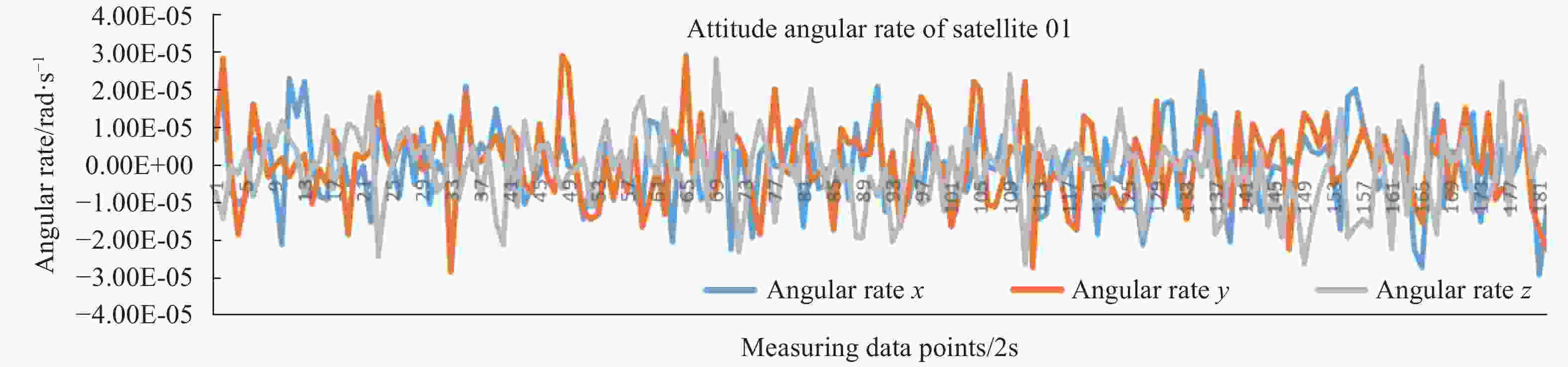
图 5 01星姿态角速率
Figure 5. Attitude angular rate of satellite 01

图 6 02星姿态角速率
Figure 6. Attitude angular rate of satellite 02
-
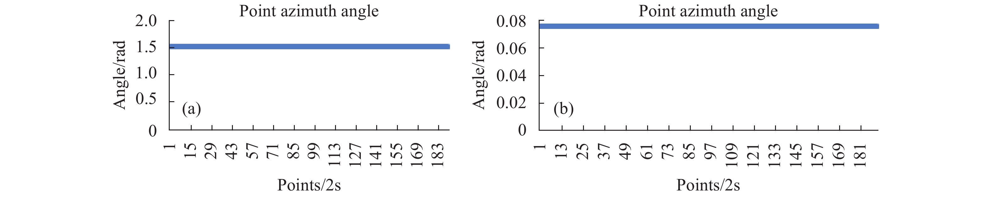
XY-2双星为圆轨道,轨道参数接近,双星相对位置在地面站可视时间段内变化较小,如图7、图8所示,01星为凝视方,方位角和俯仰角保持不变。02星为扫描方,方位角和俯仰角螺旋变大,符合螺旋扫描的特点。根据地面标定结果,双星姿态指向有一定的差异,导致指向中心有一定角度差异。

图 7 01星指向变化
Figure 7. Direction change in satellite 01

图 8 02星指向角度变化
Figure 8. Direction change in satellite 02
卫星在发射过程中有较强的振动,另外加上失重的影响,导致太空中卫星和激光通信载荷的相互位置关系与地面有较大变化,为此需要重新标定指向偏置中心。根据当前指向角度测试的结果,确定下次的指向中心偏置点,如公式(11)所示,由于扫描时步进间隔为70 ms,而遥测量下传时间为2 s一次,因此无法准确得出扫中对方的时刻信息,也就无法得出指向偏置中心,通过逐次逼近的方式得出准确的偏置中心,由测试结果1中的点为扫中对方星时对应的点的范围,得出下一次的扫描中心偏置点为(2 000,−800),单位为μrad,其扫描范围为3.5 mrad,如图9所示。

图 9 中心点1及扫描范围1
Figure 9. Center point 1 and scanning range 1
在多次迭代测试中,后续测试中进行中心点的逼近,并减小扫描范围,如图10所示,从图中得到01星稳定的指向中心偏置点为(2160,550),同样的方法得出02星的指向中心偏置点为(−2 093,−5 976)。

图 10 扫描范围3
Figure 10. Scanning range 3
-
由于地面标定的QD跟踪点受到火箭发射和失重的影响,导致QD和激光载荷之间的相互位置关系变化,而激光载荷没有自标校系统,因此,需要标定QAPD跟踪点。如图11所示,01星上的激光通信终端和02星上的激光通信终端同时照亮对方,01星发出的光束为Laser01t02,02星发出的光束为laser02t01,此时由于laser01t02和Laser02t01的平均误差小于100 μrad,则认为两束光为同一束激光。

图 11 激光通信终端同时照亮对方示意图
Figure 11. Diagram of laser communication terminals illuminating each other at the same time
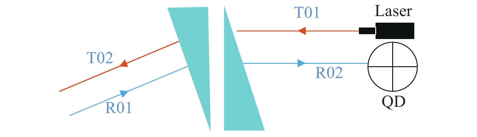
在双棱镜光路下的光路示意图如图12所示,T01为激光器发出的光,T02为T01经过双棱镜以后的出射光,R01为激光通信终端的入射光,R02为经过双棱镜光路后入射到QD上的光。由于T02和R01认为是同一束激光,则根据光的可逆性认为T01和R02位同一束光,此时,R02在QAPD上形成的偏移量即可认为是跟踪点。

图 12 双棱镜输入和输出光路
Figure 12. Input and output optical path of double prisms
将遥测采集得到的QAPD数据代入公式(16)和(17),计算得出01星的QAPD跟踪点为(−6,18),02星的QAPD跟踪点为(3,6),单位为μm。
-
在激光通信载荷双向建链测试中,01星上激光通信设备调整指向偏置点并设置跟踪点后螺旋扫描01星,02星上激光通信设备调整指向偏置点和跟踪点后凝视01星,当QAPD值超过设定的能量阈值,即判定捕获到激光,本星调整棱镜旋转角度指向对方星,双方均指向对方,判定双星建链成功,获取遥测数据,查看QAPD能量值偏离跟踪点的大小和频次,计算出跟踪精度,并对QAPD跟踪点进行微调,使其达到最优,在此基础上实现星间激光载荷的跟踪,一共进行了15次双向建链测试,捕获时间小于20 s,捕获成功率100%,捕获后双星建链时间优于2 s,15次建链测试有1次未能成功建链,建链后跟踪精度RMS值小于30 μrad。
-
文中针对XY-2号卫星上基于双棱镜的激光通信设备,采用了QAPD作为位置判断传感器的无信标光激光通信方案,对星间指向算法、扫描捕获和跟踪算法问题进行了探讨。XY-2卫星为圆轨道,轨道参数接近,双星相对位置在地面站可视时间段内变化较小,卫星姿态稳定度优于40 μrad/s,为在轨测试提供了便利条件,在此基础上对激光通信终端进行了在轨测试。
在轨测试时,进行多次迭代逼近中心偏置点,并逐步减小扫描范围,优化了指向偏差,得到01星稳定的指向中心偏置点为(2 160,550),02星的指向中心偏置点为(−2 093,−5 976)。根据光的可逆性原理,双星互指过程中双星同时照亮对方,则本星的出射光和入射光判定是同一束激光,在QAPD上形成的偏移量即可判定是跟踪点,标定后系统的跟踪点01星为(−6,18),02星为(3,6),单位为μm,最后进行了双向建链测试,在双向建链过程中对系统的跟踪点进行了微调,最终进行了15次建链测试,成功建链14次,取得了较好的结果。
致 谢: XY-2卫星激光通信载荷星间双向建链的成功得益于诸多机构的支持,感谢中国科学院上海光学精密机械研究机所的孙建锋、高敏、胡琼和鲁绍文,感谢南京航星激光通信公司的激光通信载荷研制团队,感谢航天行云科技有限公司的孙述鹏、晏也绘和周鑫。
XY-2 satellite laser communication equipment PAT test in orbit
-
摘要: 针对低轨小卫星星座的通信需求,设计了基于双棱镜和四象限雪崩光电二极管(QAPD)结构收发同轴的激光通信载荷,该方案是无信标光体制,具有体积小、轻量化和大视场的特点。文中针对双棱镜结构,给出了双棱镜输入输出光线的计算模型,在此基础上,提出了星间指向、捕获和跟踪的实现方式,并在XY-2号卫星上进行了在轨测试和验证,进行指向测试时,更新了指向偏移量,标定了QAPD跟踪点,并进行了双向建链测试。进行了15次双向建链测试表明,该激光通信载荷捕获时间小于20 s,捕获成功率达到100%,捕获后双星建链时间优于2 s,建链测试成功率达到了93%,建链后跟踪精度RMS值小于30 μrad。Abstract: According to the communication requirements of Leo satellite constellation, a laser communication equipment structure based on double Risley prisms and quadrant avalanche photodiode (QAPD) was designed. The scheme was beaconless optical system. It had the characteritics of small size, low weight and large field of view. In this paper, the calculation model of input and output light of double Risley prisms structure was given. On this basis, the interstellar of pointing, capturing and tracking was proposed, then in orbit test and verification were carried out on XY-2 satellite. The pointing offset was updated, based on pointing test, the QAPD tracking point was calibrated, and the two-way link up with the XY-2 satellite test was carried out. The bidirectional chain building test which was repeated 15 times showed that the acquisition time of the laser communication equipment was less than 20 s, and the acquisition success ratio was 100%. After the acquisition, the chain building time of the two satellites was better than 2 s and the linking success ratio reached 93%, and the RMS value of tracking accuracy was less than 30 μrad.
-
Key words:
- laser communication /
- double Risley prisms /
- pointing /
- capturing /
- tracking
-
图 2 旋转双棱镜光束指向系统示意图
Figure 2. Diagram of beam pointing system with rotating double prisms
图 4 建链测试阶段系统连接关系示意图
Figure 4. Diagram of system connection in chain building test phase
图 11 激光通信终端同时照亮对方示意图
Figure 11. Diagram of laser communication terminals illuminating each other at the same time
-
[1] Lu Zhen. Status and trends of the small satellite and micro-nano satellites [J]. Journal of Ordnance Equipment Engineering, 2018, 39(6): 1-7. (in Chinese) doi: 10.11809/bqzbgcxb2018.06.001 [2] Hu Fen, Gao Xiaoming. Development trend analysis of remote sensing small satellite for surveying and mapping application [J]. Science of Surveying and Mapping, 2019, 44(1): 132-138, 150. (in Chinese) [3] Zhang Ming. Development and challenges of LEO satellite system [J]. China Radio, 2019(3): 56-57. (in Chinese) doi: 10.3969/j.issn.1672-7797.2019.03.031 [4] Jiang Huilin, An Yan, Zhang Yalin, et al. Analysis of the status quo, development trend and key technologies of space laser communication [J]. Journal of Spacecraft TT&C Technology, 2015, 34(3): 207-217. (in Chinese) [5] Gao Duorui, Li Tianlun, Sun Yue, et al. Latest developments and trends ofspace laser communication [J]. Chinese Optics, 2018, 11(6): 901-913. (in Chinese) doi: 10.3788/co.20181106.0901 [6] Fuse T, Akioka M, Kolev D, et al. Development of a breadboard model of space laser communication terminal for optical feeder links from Geo[C]//International Conference on Space Optics 2016. International Society for Optics and Photonics, 2017, 10562: 105622X. [7] Guo Aiyan, Gao Wenjun, Zhou Aosong, et al. Beaconless acquisition tracking and pointing of inter-satellite optical communication [J]. Infrared and Laser Engineering, 2017, 46(10): 1022002. (in Chinese) doi: 1022002 [8] Uwe Sterr, Mark Gregory, Frank Heine. Beaconless acquisition for ISL and SGL, summary of 3 years operation in space and ground[C]//IEEE International Conference on Space Optical Systems and Applications, 2011: 38-43. [9] Boroson D M, Robinson B S, Murphy D V, et al. Overview and results of the lunar laser communication demonstration[C]// Proceedings of SPIE, 2014, 8971: 89710S. [10] Biswas A, Kovalik J M, Srinivasan M, et al. Deep space laser communications[C]//Proceedings of SPIE-Free Space Laser Communication and Atmospheric Propagation, 2016, 9739: 97390Q. [11] 武凤. 窄信标卫星光通信链路快速捕获和稳定跟踪方法研究[D]. 哈尔滨工业大学, 2018. Wu Feng. Research on fast acquisition and stable tracking method with narrow beacon in satellite optical communication link[D]. Harbin: Harbin Institute of Technology, 2018. (in Chinese) [12] Lu Shaowen, Gao Min, Yang Yan, et al. Inter-satellite laser communication system based on double Risley prisms beam steering [J]. Applied Optics, 2019, 58(27): 7517-7522. doi: 10.1364/AO.58.007517 [13] Gao Fei, Wang Miao. Double optical wedge optical axis pointing adjustment technology [J]. Opto-Electronic Engineering, 2018, 45(11): 60-66. (in Chinese) [14] Zhao Junli, Wu Yiming, Gao Limin, et al. Technology research on image motion compensation of the rotating double optical wedge [J]. Infrared and Laser Engineering, 2015, 44(5): 1506-1511. (in Chinese) doi: 10.3969/j.issn.1007-2276.2015.05.020 [15] Zhou Yuan, Lu Yafei, Hei Mo, et al. Analytical inverse solutions for rotational double prism beam steering [J]. Optics and Precision Engineering, 2013, 21(7): 1693-1700. (in Chinese) doi: 10.3788/OPE.20132107.1693 [16] Zhou Yuan, Lu Yafei, Hei Mo, et al. Analytic solution of optical beam steering based on rotational double prisms [J]. Optics and Precision Engineering, 2013, 21(6): 1373-1379. (in Chinese) doi: 10.3788/OPE.20132106.1373 [17] Wang Linzheng, Zou Hua, Huang Shuo, et al. Closed-loop control method of optical fiber positioning of center-opening four-quadrant detector [J]. Infrared and Laser Engineering, 2020, 49(6): 20190466. (in Chinese) [18] Lu Qian, Ren Bin, Bian Jingying. Research on acquisition and tracking technology for the four-quadrant detector [J]. Opto-Electronic Engineering, 2020, 47(3): 160-165. (in Chinese) -

 点击查看大图

图(12)
计量
- 文章访问数: 1530
- HTML全文浏览量: 186
- PDF下载量: 123
- 被引次数: 0


