


-
大口径望远镜必须有很高的分辨率和良好的跟踪性能才能保证望远镜观测图像的质量和跟踪天体的精确度。为了收集来自遥远天体暗弱、微小的信号以满足人类探测深空需求,天文望远镜的口径越来越大。随着望远镜口径的增加,望远镜传动、跟踪驱动控制技术也在不断发生演变。从早期的涡轮蜗杆传动(胡克望远镜)到齿轮传动(多目标、多光纤赤道式望远镜ATT[1]等)、摩擦传动(Gemini south及Gemini north[2]等),直至发展到今天大型天文望远镜普遍采用的拼接电机对轴系进行直接驱动,如欧南台的VLT望远镜[3]、日本国家天文台的SUBARU望远镜[4]和西班牙的GTC望远镜[5]。SUBARU和VLT直接驱动的成功,使得针对大口径天文望远镜的直接驱动电机及其相关技术成为研究的热点。世界上已经开始研究的30~100 m光学望远镜,如欧洲39 m的极大望远镜ELT[6]和以美国为首的多国参与建造的TMT[7],都在建造计划中提到将采用拼接直线电机直接驱动技术。
大型望远镜轴系跟踪及指向精度是影响观测精度的主要因素,而电机本身受设计、制造工艺及逆变驱动技术的影响,气隙磁场的畸变和逆变器的非线性特性使永磁同步电机电流中含有大量高次谐波,电流波形发生畸变,导致电机电磁转矩脉动、绕组发热等不利于电机运行的因素。这对大型望远镜来说,转矩波动过大很难保证大型望远镜跟踪目标的像质稳定性,而绕组发热量过大影响电机使用寿命和望远镜观测精度,降低望远镜轴系转矩波动是提高观测控制精度的重要因素。文中提到的拼接弧线电机是我国自主研制的轴系驱动电机,定制电机驱动控制系统的自主研制也是工作中的重中之重。
电机的结构设计、制造工艺、驱动器开关器件和非线性等因素是产生电流谐波的主要因素,从而导致电机损耗增加和转矩波动,使系统的控制性能变差。针对常规电机的电流谐波,国内外学者开展了相关的研究工作以期望降低电流谐波:改进电机本体结构,如分数槽法和斜槽法;改善逆变器,如使用前馈补偿法逆变器的死区;控制算法电压注入法、自适应神经网络改善波形畸变等方法被广泛讨论。如参考文献[8-11]仅仅是针对电机本体结构改进降低齿槽转矩,而拼接弧线电机设计时已从本体结构上改进。参考文献[12]提出构建谐波观测器的方法抑制谐波,参考文献[13]构建了一种自适应线性神经网络的方式抑制谐波,但这两者分别对凸极和内置式永磁同步电机进行了实验,对表贴式、超低速运行的拼接弧线电机的作用效果尚未可知。因此,针对大型天文望远镜跟踪精度的需要,文中开展了新型拼接弧线电机谐波抑制方法研究,对比分析了传统PI和准比例谐振电流谐波抑制方法。
-
近年来,随着永磁材料和电力电子技术的发展,永磁同步电机以高转矩密度、良好的转矩特性、高控制精度及低振动噪声得到了高速发展。而正弦波永磁同步电机启动牵引力大、功率因数高、发热小、允许的过载电流大、调速范围大等优点满足大型望远镜轴系跟踪控制的需求,根据望远镜的运行特点,拼接直线电机自VLT得到成功应用以来受到了很多大型天文望远镜的青睐。
但VLT是双气隙的分段式拼接电机,定子是“汉堡”型的绕组,这种结构的电机有机械加工难度大、输出转矩脉动大等缺点。笔者课题根据永磁同步电机特点及应用,再加上借鉴国外大口径望远镜所用的拼接永磁同步电机的经验由中国科学院国家天文台南京天文光学技术研究所自主研制。电机结构示意图如图1所示,拼接弧线电机是6组电动机驱动望远镜轴系,2组用作测速机,使其保持良好的跟踪性能。
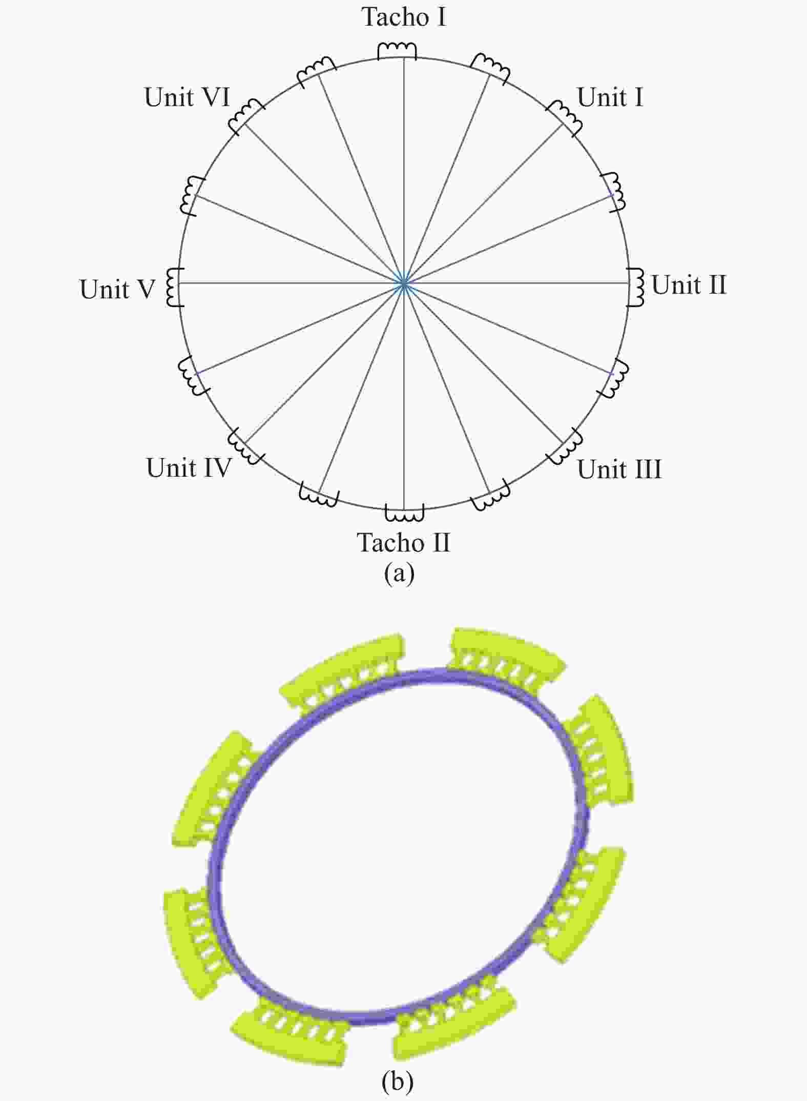
图 1 大型天文望远镜拼接弧线电机结构分布示意图。(a)定子绕组;(b)机械结构
Figure 1. Structure distribution of segmented arc motor for large aperture telescope. (a) Stator winding; (b) Mechanical structure
-
常规的永磁同步电机在使用时常忽略铁芯饱和及转子磁场在气隙中的谐波因素,认为电机工作在线性状态下,这对高精度跟踪的望远镜轴系跟踪系统来说所引起的过大转矩波动有可能引起目标不在视场中,因此,在分析电机数学模型时需要考虑电机的非线性因素。
理想状况下,拼接弧线电机在同步旋转d-q坐标系下的定子磁链方程为:
$$\left\{ {\begin{array}{*{20}{l}} {{\psi _d} = {L_d}{i_d} + {\psi _r}} \\ {{\psi _q} = {L_q}{i_q}} \end{array}} \right.$$ (1) 定子电压平衡方程为:
$$\left\{ {\begin{array}{*{20}{l}} {{u_d} = {R_s}{i_d} + {L_d}{{\dot i}_d} + {{\dot \psi }_{_r}} - {\omega _e}{i_q}{L_q}} \\ {{u_q} = {R_s}{i_q} + {L_q}{{\dot i}_q} + {\omega _e}{i_d}{L_d} + {\omega _e}{\psi _r}} \end{array}} \right.$$ (2) 电磁转矩方程为:
$${T_e} = \frac{3}{2}{p_n}[{\psi _r}{i_q} + ({L_d} - {L_q}){i_d}{i_q}]$$ (3) 实际电机在运行过程中,受永磁体制造及工艺上的限制,永磁体产生的谐波含量很大[14],由于磁场分布不是绝对的正弦波分布,为了观察电路中的谐波分量,对其进行傅里叶变换,永磁体在某相绕组产生的转子磁场在气隙中不同分布位置的傅里叶展开式为:
$$\begin{array}{l} {\varPsi _u} = {\psi _r}\cos \theta + {\psi _{3r}}\cos 3\theta + {\psi _{5r}}\cos 5\theta + \cdots \\ \end{array} $$ (4) 此时根据三角函数计算合并电机电压平衡方程为:
$$ \left\{ {\begin{array}{*{20}{l}} \begin{array}{l} {u_d} = {R_s}{i_d} + {L_d}{{\dot i}_d} - {\omega _e}{i_q}{L_q} + {\psi _{6d}}{\omega _e}\sin 6\theta +{\psi _{12d}}{\omega _e}\sin 12\theta + \cdots \\ \end{array} \\ \begin{array}{l} {u_q} = {R_s}{i_q} + {L_q}{{\dot i}_q} + {\omega _e}{i_d}{L_d} + {\omega _e}{\psi _r} + {\psi _{6q}}{\omega _e}\cos 6\theta +\\ \;\;\;\;\;\;\;\;{\psi _{12q}}{\omega _e}\cos 12\theta + \cdots \\ \end{array} \end{array}} \right. $$ (5) 电磁转矩为:
$$ \begin{split} {T_e} =& \dfrac{3}{2}{p_n}[{\psi _r}{i_q} + ({L_d} - {L_q}){i_d}{i_q} +\\ &({\psi _{6d}}\sin 6\theta + {\psi _{12d}}\sin 12\theta ) + \cdots ){i_d} +\\ &({\psi _{6q}}\cos 6\theta + {\psi _{12q}}\cos 12\theta ) + \cdots ){i_q}] \\ \end{split} $$ (6) 式中:
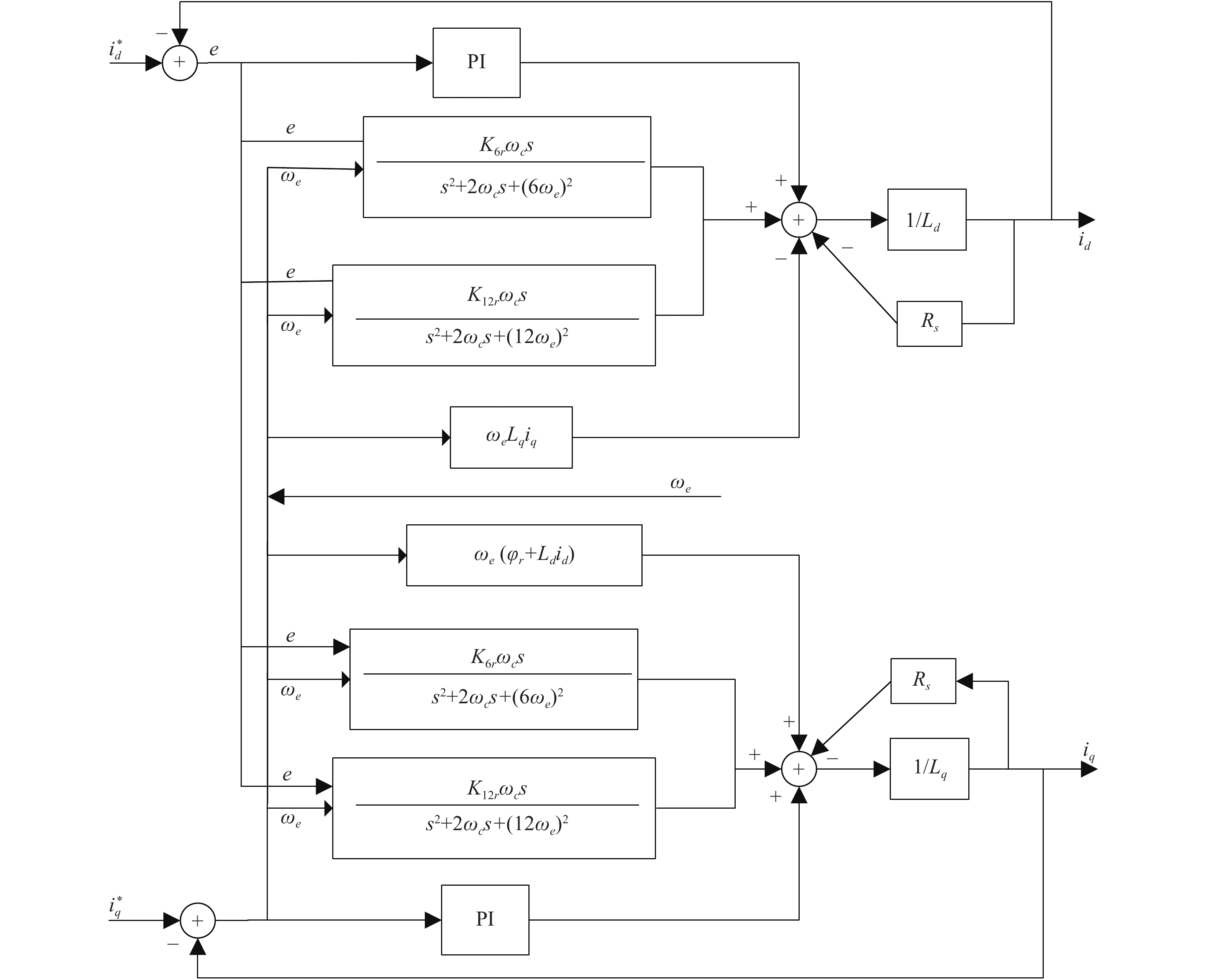
${\psi _r}$ 、${\psi _{3r}}$ ,${\psi _{5r}}$ 为转子磁链基波、3次波和5次波;${\psi _{6d}}$ 、${\psi _{6q}}$ 、${\psi _{12d}}$ 和${\psi _{12q}}$ 是转子磁链5次波、7次波、11次波和13次波的三角函数合成而来;$\theta $ 为转子位置。由以上分析可以看出,电机在运行过程中存在电压及电流高次谐波,转矩中存在脉动分量,这对望远镜的运行是很不利的,转矩中的6次和12次谐波主要由5次、7次、11次和13次磁链产生,因此只要在控制过程中抑制这些分量就能抑制转矩波动,电机的电流环工作动态示意图如图2所示。
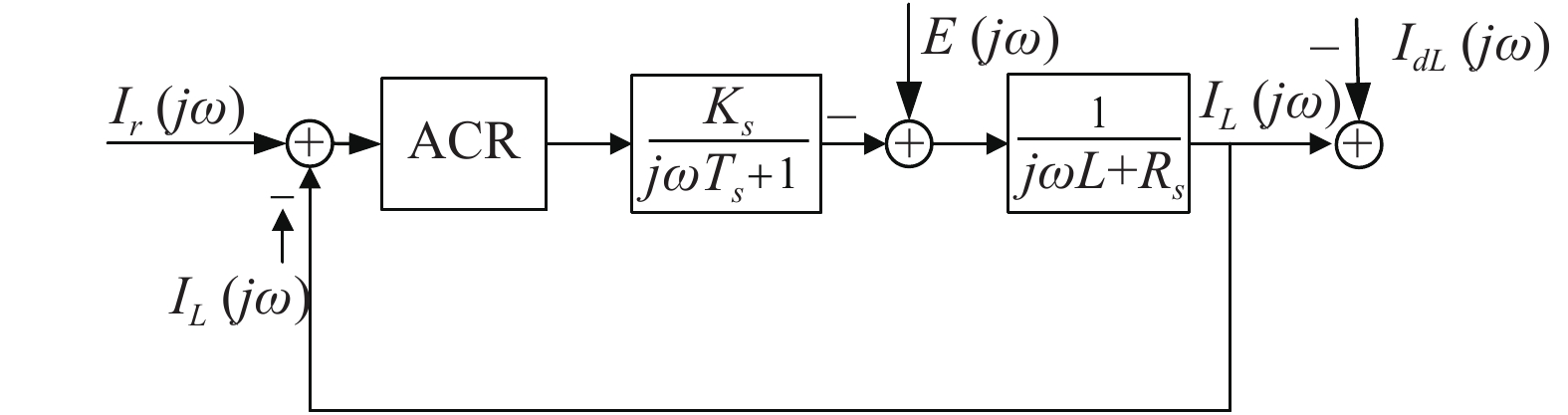
图 2 电流环工作动态结构框图
Figure 2. Dynamic structure of motor current loop
-
PI控制器存在稳态误差,为了消除稳态误差,日本学者SATO[15]最早提出了比例谐振(Proportional Resonant,PR)控制器,在PI的基础上增加了无损谐振环节,在谐振频率处使控制器的增益无穷大,比例谐振控制器的传递函数为:
$$G(s) = {k_p} + \dfrac{{2{k_r}s}}{{{s^2} + \omega _0^2}}$$ (7) 理想状况下,比例谐振控制器的伯德图如图3所示,图中谐振点处增益无穷大,理论上可实现交流信号的无静差跟踪调节。

图 3 理想状况PR控制器伯德图
Figure 3. PR controller Bode diagram on ideal condition
根据PR伯德图,谐振控制器在谐振点外增益迅速衰减,易引起控制系统的高增益频带过窄,使系统对输入信号的敏感度增加,当输入信号的频率偏离给定输入信号的频率会引起系统波动,导致系统不稳定。同时电流环受反电势、负载扰动及参考输入等的影响,PR控制器难以实现,因此在实际应用中为保证系统的稳定性,引入改进型的PR控制器,适当增加系统带宽,称为准谐振控制器,其传递函数为:
$$G(s) = {k_p} + \frac{{2{k_r}{\omega _c}s}}{{{s^2} + 2{\omega _c}s + \omega _0^2}}$$ (8) 由公式(8)可知,该控制器主要受三个参数的影响:
${k_p}$ 、${k_r}$ 及${\omega _c}$ ,为了解参数对系统的影响,分别分析三个参数独立变化时的伯德图。${k_r} = 0$ 、${\omega _c} = 1$ 时${k_p}$ 变化对系统的影响,由PI控制器基本理论知,随着比例系数${k_p}$ 的增加增益也增加;${k_p}{\rm{ = }}0$ 、${k_r} = 1$ 时${\omega _c}$ 变化随着${\omega _c}$ 增加带宽变窄;${k_p}{\rm{ = }}0$ 、${\omega _c} = 1$ 时${k_r}$ 变化随着${k_r}$ 的增加增益增加。两者伯德图分别如图4和图5所示,由此可知选择合适的${\omega _c}$ 和${k_r}$ 可有效抑制谐振点外的扰动。
图 4
${\omega _c}$ 变化PR控制器伯德图Figure 4. PR controller Bode diagram when
${\omega _c}$ varying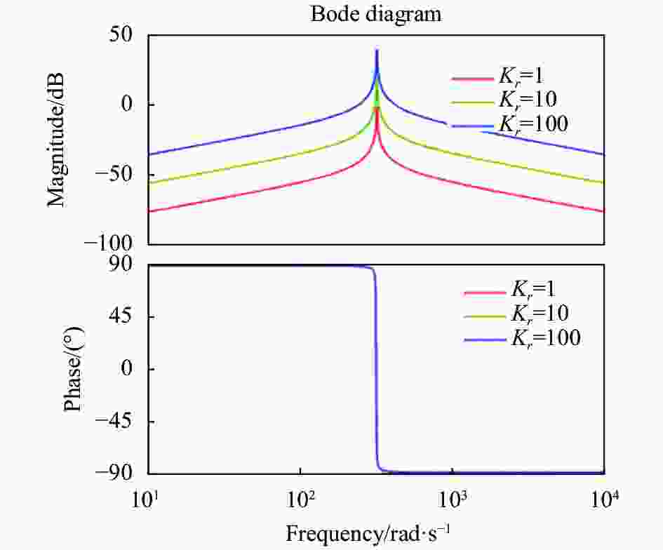
图 5
${K_r}$ 变化PR控制器伯德图Figure 5. PR controller Bode diagram when
${K_r}$ varying -
在拼接弧线电机驱动中,逆变器受功率器件非线性、开关延迟的影响及转子磁场在空间分布不均匀,电机电流会产生谐波,同时增加铜耗,从而导致电机运行不平稳,产生转矩脉动。通过以上理论分析,只要在控制中加入谐振控制器就能有效地抑制电流谐波。
为实现拼接弧线电机驱动的大型望远镜良好的跟踪性能,提高系统的动态响应性能,抑制转矩波动实现系统的低速平稳运行的有效途径就是有效抑制电流谐波分量,根据电机数学模型可设计控制器,如图6所示。根据以上分析及谐波抑制原理可将控制器的谐振点设计在
$6{\omega _e}$ 及$12{\omega _e}$ 处,从而有效消除电流的5次、7次、11次和13次谐波。
图 6 电流环准比例谐振器的控制器设计
Figure 6. Quasi-PR controller design of the current loop
对准谐振控制器公式(8)进行离散化,考虑到望远镜运行速度很低,设系统的带宽为
${\omega _c} = 10$ rad/s,当望远镜运行速度为2 (°)/s时${\omega _e} = 8.88$ rad/s,此时准谐振控制可用双线性近似法进行离散化,可得:$$G( {\textit{z}}) = \dfrac{{{b_0} + {b_1}{ {\textit{z}}^{ - 1}} + {b_2}{ {\textit{z}}^{ - 2}}}}{{1 + {a_1}{ {\textit{z}}^{ - 1}} + {a_2}{ {\textit{z}}^{ - 2}}}}$$ (9) 离散化后控制器的输出为:
$$ \begin{split} y(k) =& - {a_1}y(k - 1) - {a_2}y(k - 2) +\\ & {b_0}e(k) + {b_1}e(k - 1) + {b_2}e(k - 2) \\ \end{split} $$ (10) 选择合适的离散化时间,计算出离散系数
${b_0} = $ $ 0.002\;5$ ,${b_1} = 0$ ,${b_2} = - 0.002\;5$ ,${a_1} = 1.999\;9$ ,${a_2} = 0.999\;9$ ,根据离散化的控制器在DSP里编程即可实现准比例谐振控制器。 -
为了验证算法的有效性,首先将上述控制策略用Simulink做仿真,拼接弧线电机定子电阻
${R_s} = 20.1\;\Omega $ ,电感$ {L_s} = 1.56 $ H,极对数${P_n} = 200$ ,图7为电机和驱动控制实验平台实物图。
图 7 拼接弧线电机驱动控制平台。(a)电机实物图;(b)驱动控制电路实物图
Figure 7. Drive and control platform of segmented arc PMSM. (a) Physical drawing of arc PMSM; (b) Drive and control circuit board
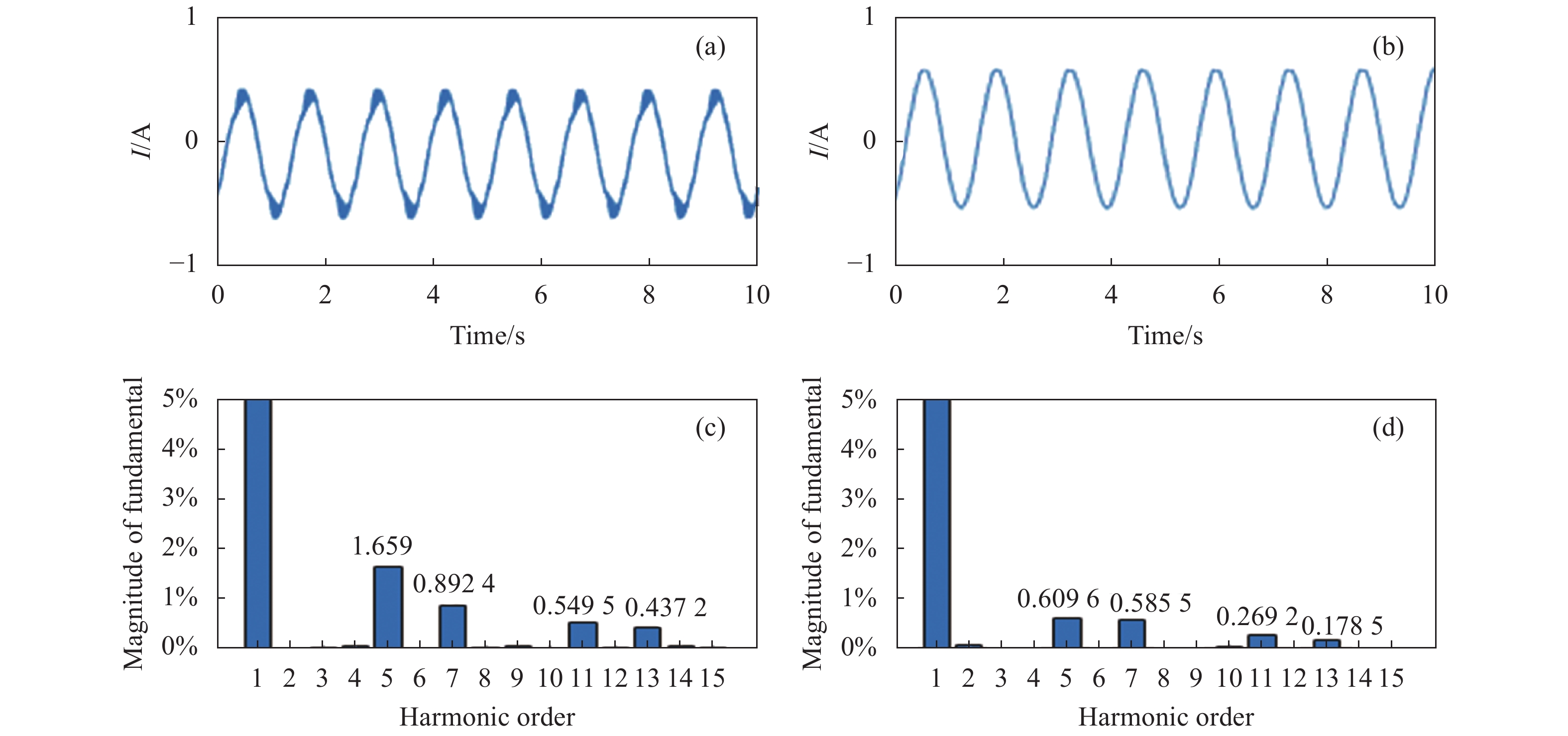
为验证准比例谐振是否能有效抑制电流比谐波,分别采用PI控制器和QPR控制器对拼接弧线电机的电流环进行仿真,仿真结果电流波形和各次谐波结果如图8所示,谐波改善情况如表1所示。由表1可知5次谐波分量削弱了81.4%,7次谐波分量削弱了77.9%,11次谐波分量削弱了70.4%,13次谐波分量削弱了90.5%,从而证明准比例谐振控制器大大抑制了电流谐波。

图 8 PI和PR两种控制算法电流波形及谐波分析仿真对比。(a) PI控制算法一个周期的电流波形; (b) PR控制算法一个周期的电流波形; (c) PI仿真电流各次谐波含量幅值百分比; (d) QPR仿真电流各次谐波含量幅值百分比
Figure 8. Simulations comparison of current wave and harmonic analysis between PI and PR controller. (a) Current wave of one period (PI); (b) Current wave of one period (QPR); (c) Harmonics percentage of magnitude of current of simulation (PI); (d) Harmonics percentage of magnitude of current of simulation (QPR)
表 1 PI和QPR算法电流各次谐波仿真对比
Table 1. Current harmonic percentage of simulation comparison between PI and QPR
Harmonics N Fundamental harmonic of PI Fundamental harmonic of QPR Weaken of all harmonics 5 0.6638% 0.1231% 81.4% 7 0.8652% 0.1908% 77.9% 11 0.3389% 0.1005% 70.4% 13 0.3164% 0.0298% 90.5% -
为进一步验证上述仿真结果的有效性,采用TI公司的TMS320F28335为控制器,驱动器自主研发,分别采用PI算法及QPR方法进行实验对比,结果如图9所示,分析如表2所示。
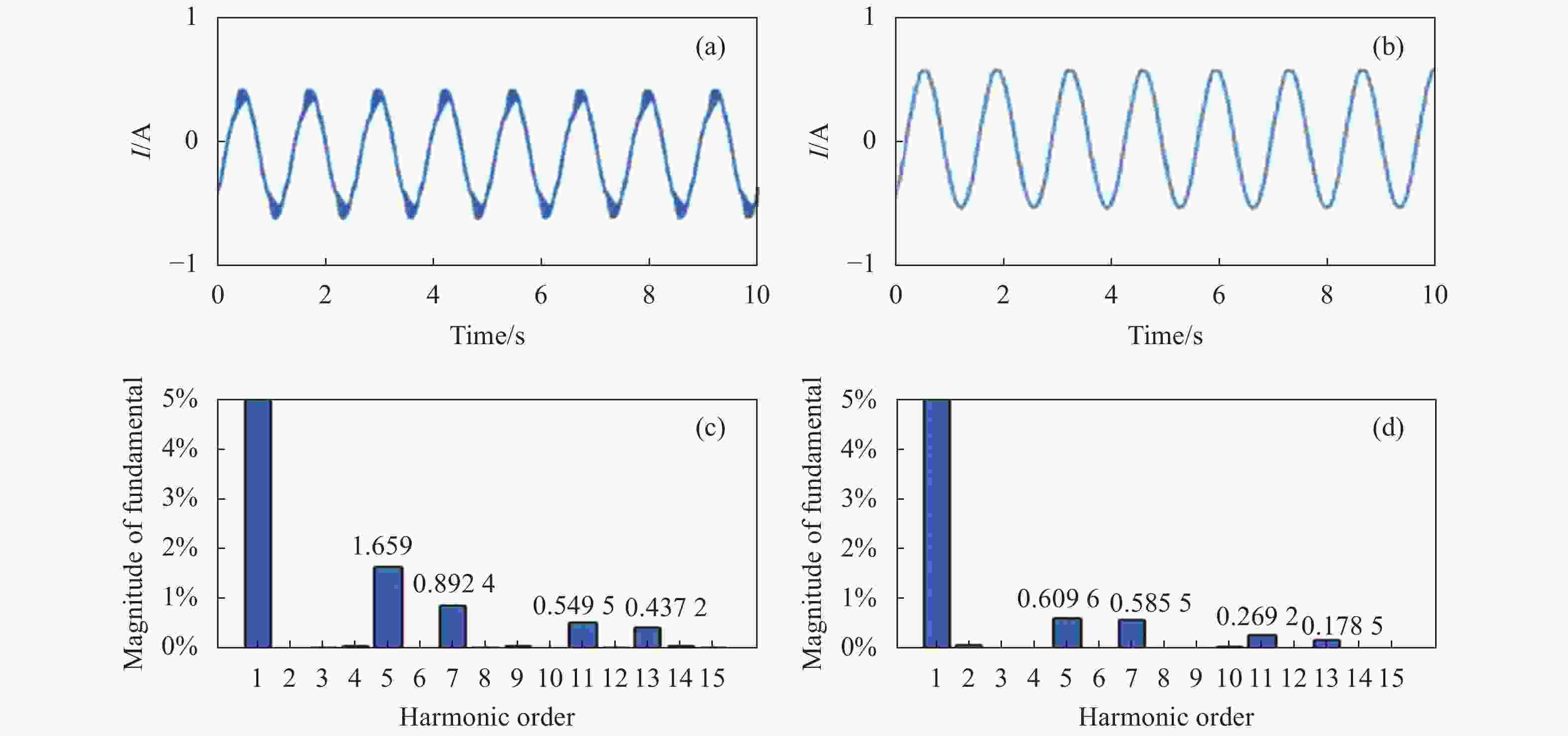
图 9 PI和PR两种控制算法电流波形及谐波分析的实验对比。(a) PI控制算法实验电流波形;(b) PR控制算法实验电流波形;(c) PI实验电流各次谐波含量幅值百分比;(d) QPR实验电流各次谐波含量幅值百分比
Figure 9. Experiments comparison of current wave and harmonic analysis between PI and PR controller. (a) Current wave of PI; (b) Current wave of QPR; (c) Magnitude percentage of current harmonics of experiment (PI); (d) Magnitude percentage of current harmonics of experiment (QPR)
表 2 PI和QPR算法电流各次谐波实验对比
Table 2. Current harmonic percentage of experiment comparison between PI and QPR
Harmonics N Fundamental harmonic of PI Fundamental harmonic of QPR Weaken of all harmonics 5 1.659% 0.6096% 63.3% 7 0.8924% 0.5855% 34.4 % 11 0.5495% 0.2692% 51.0% 13 0.4372% 0.1785% 59.2% 从实验结果可知,采用QPR控制方法,各次谐波得到不同程度的削弱,根据结果分析出5次谐波分量削弱了63.3%,7次谐波分量削弱了34.4%,11次谐波分量削弱了51%,13次谐波分量削弱了59.2%,证明采用QPR控制器可以有效改善电流环的谐波含量,从而提高大型望远镜的转矩波动,有助于提高跟踪精度。
-
根据谐振控制器在谐振点外增益迅速衰减的特点,利用谐振特点及拼接弧线电机电流特点所设计的电流环调节器可实现交流信号的无静差跟踪调节。仿真和实验都表明当选定谐振频率为6N倍谐波分量时,可有效地抑制分量较大的5次、7次、11次及13次谐波分量,从而改善电流波形,降低转矩波动,有助于提高望远镜的跟踪精度。
Current harmonics suppression of the large aperture telescope based on segmented arc PMSM
-
摘要: 望远镜口径的增加使得其轴系驱动电机越来越大,近年来拼接电机成为国际上研究的热点。拼接弧线永磁电机的电流谐波影响大型天文望远镜目标观测轴系跟踪精度,文中根据拼接弧线电机的数学模型及谐波分析,提出了一种基于准比例-谐振控制器的电流谐波抑制算法,并设计了单元拼接弧线电机相应的电流控制器。仿真和实验分别对比了PI和准比例谐振控制器对电流谐波的影响。实验结果表明,采用准比例谐振控制器时,拼接弧线电机定子电流中的5次谐波分量削弱了63.3%,7次谐波分量削弱了34.4%,11次谐波分量削弱了51%,13次谐波分量削弱了59.2%,大大降低了拼接弧线电机电流谐波,有助于提高望远镜跟踪精度。Abstract: With the increasing of telescope aperture, the main axis driving motor is becoming larger and larger, and the segmented motor has become a hot topic in international astronomy research today. The current harmonics of the segmented Arc Permanent Magnet Synchronous Motor (APMSM) influence the tracking accuracy of the large aperture telescope. According to the mathematical model and harmonic analysis of segmented APMSM, a current harmonic suppression algorithm based on Quasi-Proportional Resonant (QPR) controller was proposed, and the current controller of unit segmented APMSM was designed. The effect of PI and the QPR controller on current harmonics from simulation and experiment was compared respectively. The experimental results show that when using QPR controller, the 5th harmonic order, the 7th harmonic order, the 11th harmonic order and the 13th harmonic order of the stator current are reduced by 63.3%, 34.4%, 51% and 59.2%, respectively, and the current harmonics of segmented APMSM can be reduced greatly, the tracking accuracy of the large aperture telescope can be improved.
-
Key words:
- current harmonics suppression /
- segmented APMSM /
- QPR controller /
- PI controller /
- telescope
-
图 1 大型天文望远镜拼接弧线电机结构分布示意图。(a)定子绕组;(b)机械结构
Figure 1. Structure distribution of segmented arc motor for large aperture telescope. (a) Stator winding; (b) Mechanical structure
图 4
${\omega _c}$ 变化PR控制器伯德图Figure 4. PR controller Bode diagram when
${\omega _c}$ varying
图 7 拼接弧线电机驱动控制平台。(a)电机实物图;(b)驱动控制电路实物图
Figure 7. Drive and control platform of segmented arc PMSM. (a) Physical drawing of arc PMSM; (b) Drive and control circuit board
图 8 PI和PR两种控制算法电流波形及谐波分析仿真对比。(a) PI控制算法一个周期的电流波形; (b) PR控制算法一个周期的电流波形; (c) PI仿真电流各次谐波含量幅值百分比; (d) QPR仿真电流各次谐波含量幅值百分比
Figure 8. Simulations comparison of current wave and harmonic analysis between PI and PR controller. (a) Current wave of one period (PI); (b) Current wave of one period (QPR); (c) Harmonics percentage of magnitude of current of simulation (PI); (d) Harmonics percentage of magnitude of current of simulation (QPR)
图 9 PI和PR两种控制算法电流波形及谐波分析的实验对比。(a) PI控制算法实验电流波形;(b) PR控制算法实验电流波形;(c) PI实验电流各次谐波含量幅值百分比;(d) QPR实验电流各次谐波含量幅值百分比
Figure 9. Experiments comparison of current wave and harmonic analysis between PI and PR controller. (a) Current wave of PI; (b) Current wave of QPR; (c) Magnitude percentage of current harmonics of experiment (PI); (d) Magnitude percentage of current harmonics of experiment (QPR)
表 1 PI和QPR算法电流各次谐波仿真对比
Table 1. Current harmonic percentage of simulation comparison between PI and QPR
Harmonics N Fundamental harmonic of PI Fundamental harmonic of QPR Weaken of all harmonics 5 0.6638% 0.1231% 81.4% 7 0.8652% 0.1908% 77.9% 11 0.3389% 0.1005% 70.4% 13 0.3164% 0.0298% 90.5%  下载: 导出CSV
表 2 PI和QPR算法电流各次谐波实验对比
Table 2. Current harmonic percentage of experiment comparison between PI and QPR
Harmonics N Fundamental harmonic of PI Fundamental harmonic of QPR Weaken of all harmonics 5 1.659% 0.6096% 63.3% 7 0.8924% 0.5855% 34.4 % 11 0.5495% 0.2692% 51.0% 13 0.4372% 0.1785% 59.2%
下载: 导出CSV
-
[1] Minnett H C. Progress on the 150 inch Anglo-Australian telescope [C]//Proceedings of the Astronomical Society of Australia, 1971(60): 2-6. [2] Burns M K. Servo simulation and modeling for Gemini 8-m telescopes [C]//Proc of SPIE, 1995, 2479: 217-232. [3] Erm T, Gutierrez P. Integration and tuning of the VLT drive systems [C]//Proc of SPIE, 2000, 4004: 490-499. [4] Noguchi T, Tanaka W, Sasaki T, et al. Evaluation of the Subaru telescope control system in-shop test erection [C]//International Society for Optics and Photonics, 1998, 3351: 361-366. [5] Suárez M, Rosich J, Ortega J, et al. The GTC main axes servos and control system [C]//Proc of SPIE, 2008, 7019: 70190J. [6] Marchiori G, Busatta A, Ghedin L, et al. The E-ELT Project: the telescope main structure detailed design study [C]//Proc of SPIE, 2012, 8444: 8444O. [7] Erm T M, Seppey A. A cost effective direct drive option for the Thirty Meter Telescope [C]//Proc of SPIE, 2006, 6273: 627335. [8] Tang Xu, Wang Xiuhe, Tian Mengmeng, et al. Study of reduction methods of cogging torque in line-start permanent magnet synchronous motor by changing the parameters of stator teeth and slots [J]. Transaction of China Electrotechnical Society , 2016, 31(23): 1-8. (in Chinese) [9] Shi Songning, Wang Dazhi. Magnet skewing optimization method for reducing cogging torque in permanent magnet drive [J]. Transaction of China Electrotechnical Society , 2015, 30(22): 27-32. (in Chinese) [10] Hu Xiaofei, Liu Chao, Wang Yi, et al. Analysis and optimization of single phase brushless slotted limited-angle torque motor [J]. Transaction of China Electrotechnical Society, 2019, 34(13): 2744-2751. (in Chinese) [11] Islam R, Husain I, Fardoun A, et al. Permanent-magnet synchronous motor magnet designs with skewing for torque ripple and cogging torque reduction [J]. IEEE Transactions on Industry Applications, 2009, 45(1): 152-160. doi: 10.1109/TIA.2008.2009653 [12] Zhang Jian, Wen Xuhui, Li Wenshan, et al. Research on harmonic current suppression strategies of permanent magnet synchronous motor systems based on harmonic observers [C]//Proceedings of the CSEE, 2020, 40(10): 3336-3349. (in Chinese) [13] Wang Shuo, Kang Jinsong. Harmonic extraction and suppression method of permanent magnet synchronous motor based on adaptive linear neural network [J]. Transaction of China Electrotechnical Society , 2019, 34(4): 654-663. (in Chinese) [14] Tang Renyuan. Moden Permanent Magnet Machines [M]. Beijng: Machinery Industry Press, 2005. (in Chinese) [15] Sato Y, Ishizuka T, Nezu K, et al. A new control strategy for voltage-type PWM rectifiers to realize zero steady-state control error in input current [J]. IEEE Transactions on Industry Applications, 1998, 34(3): 480-486. doi: 10.1109/28.673717 -

 点击查看大图

计量
- 文章访问数: 324
- HTML全文浏览量: 99
- PDF下载量: 13
- 被引次数: 0


