


 下载:
下载:


-
激光主动探测系统的发射波长短,能够实现高分辨率、高精度目标探测。然而随着探测距离的增加,激光回波能量衰减严重,甚至仅有光子量级,传统光电探测手段难以有效检测微弱激光回波信号[1]。近年来,高灵敏度单光子探测技术成为远距离激光探测的重要手段,主要通过单点、线阵或面阵探测器,结合光束扫描实现探测与成像[2]。面阵单光子探测器的通道数多,系统发射一个激光脉冲能够同时采集视场的高分辨率三维信息,可进行扫描、凝视等模式工作,实现目标的精确探测、跟踪与识别等目的,是一种高效的探测手段,成为目前国际上的研究热点[3-5]。
基于半导体技术的盖革APD阵列具有较高集成度,是常用的面阵单光子探测器[6]。采用盖革APD阵列的激光三维成像系统体积小、功耗低,在三维地形测绘、目标侦察与监视、激光主动成像精确制导等领域展现出了极大的应用前景。美国麻省理工学院林肯实验室自2001年提出了基于盖革APD阵列的激光三维成像雷达,并先后研制了Gen系列三代系统[7]、Jigsaw[8]、ALIRT[9]、HALOE、MACHETE、AOSTB[10]等样机,实现了机载高分辨三维地形测绘、穿过遮挡物缝隙成像等试验,将传统激光雷达的探测区域覆盖率提高了10倍以上,验证了全天时成像能力。Harris公司在林肯实验室的技术基础上,基于128×32规模InGaAs盖革APD阵列发展了IntelliEarth系统,探测距离大于6 km,空间分辨率优于25 cm,实现了大视场机载三维地形测绘[11]。近年来国内在盖革APD阵列方面取得了突破,促进了激光单光子三维成像研究[12-13]。孙剑锋等人基于32×32面阵盖革APD,搭建了1 570 nm激光主动成像系统,最远获得了外场3.9 km处的目标轮廓[14]。谢绍禹等人使用32×32盖革APD探测器对室外1 km楼房进行了成像,并将空间分辨率提高了4倍[4]。
在激光探测系统中,面阵单光子探测器单像元单脉冲平均接收的光子数通常小于1,像元对回波信号进行概率性探测,记录离散的光子计数,因此与传统的回波能量测量方式具有较大的差异[15-16]。文中基于目前国内规模最大的面阵单光子探测器,搭建1 064 nm激光主动探测实验装置,对室外目标进行凝视探测,采集回波光子数据。单光子探测器受噪声影响较大,存在死时间、非线性响应等问题,需要大量累积回波脉冲来提高信号探测概率,但耗时较多。为此,除了发展高性能的单光子探测器外,光子计数图像信号处理方法对于实现高质量成像也具有重要作用[17-18]。文中针对累积光子数较少情况下成像精度低的问题,分析单光子探测过程,通过正则化方法来提升图像重构质量。
-
文中基于面阵单光子探测器搭建了激光探测实验装置,通过脉冲法测距原理来实现三维成像。该实验装置的成像原理如图1所示,激光发射和接收采用了分离的光学孔径,接收光学系统将回波信号投影在面阵探测器上,不同像元测量不同方向回波到达时间,转换为角度-角度-距离信息。

图 1 基于面阵探测器的激光脉冲三维成像原理图
Figure 1. Schematic diagram of 3D imaging using laser pulses and array detector
该装置采用Nd:YAG微片激光器产生中心波长1 064 nm的高重频激光脉冲,实现与高帧频单光子探测器同步工作,来测量脉冲飞行时间(ToF)。该激光器在外部时序驱动下,内部通过被动调Q技术产生重复频率1 kHz、脉冲能量80 μJ高峰值功率激光。激光器谐振腔被动调Q过程具有较大的不稳定性,脉冲出射时间抖动约为200 ns,为此利用高速APD测量激光脉冲出射信号,用于触发单光子探测器开启一帧探测。
与面阵探测器匹配的激光照明方式主要包括泛光照明与分束照明两种[19]。为了降低照明光场与接收视场的配准难度,该装置采用了单束激光的泛光照明。原始激光束在横截面上具有不均匀的光强空间分布,呈现高斯分布,如图2(a)所示。为了提高照明效率,该装置采用非球面镜光束整形器piShaper,对光束轮廓进行了整形,获得了如图2(b)所示的均匀分布平顶光束。整形后输出为准直的平顶光束,光束尺寸为6 mm,转化效率几乎为100%。

图 2 (a) 原始激光束的光强空间分布,(b) 整形后光束的光强空间分布
Figure 2. (a) Spatial intensity distribution of original laser beam, (b) spatial intensity distribution of laser beam after reshaping
该装置采用口径25.4 mm、焦距75 mm的小口径镜头将激光回波成像在面阵单光子探测器上。为了降低背景光噪声,镜头前放置了3 nm窄带滤波片,透过率为80%。面阵单光子探测器及相机实物如图3所示,其基于InGaAs材料APD,对0.9~1.6 μm近红外波段具有较高的量子效率(>20%@1 064 nm);APD像元为背照式设计,像元敏感区域直径10 μm和像元间距50 μm。APD阵列前方安装了微透镜阵列,将光学填充因子提高到60%。探测过程中,设置APD反向偏压58.5 V,使其工作在盖革模式;通过半导体制冷器(TEC)将芯片制冷至−15 ℃,相应暗计数率约为20 kHz。

图 3 面阵单光子探测器及相机实物图
Figure 3. Single-photon APD detector array and integrated camera
面阵单光子探测器所有像元工作在帧同步模式,通过阵列集成读出电路(ROIC)采集探测器雪崩时刻,计时精度2 ns,数据读出率最大20 kHz。计时电路设计的读出位数12bit,对应最大门控时间4 μs。在一次门控时间内,计时电路不具有多脉冲计数能力,像元只能记录最早产生原初电子的信号或噪声,后续的雪崩事件将被无法被记录。另外,盖革模式下雪崩过程将很快饱和,探测器无法分辨入射光子数,仅能探测光子的有无。
-
如上所述,单光子探测器无法直接测量回波信号能量,而是测量信号到达时间,其响应灵敏度接近光子散粒噪声,适合于极微弱光条件下的信号探测。文中开展较远距离三维成像实验,使得单像元单脉冲平均探测光子数远小于1(~0.1光子/像元/脉冲),充分利用单光子探测器高灵敏度光子计数的特性。根据光的量子性质,单光子探测为泊松过程,单位时间内测量的光子数目服从泊松分布,均值由光子入射率决定。像元
$i$ 接收的激光脉冲回波光强为[20-21]:$${r_i}(t) = {a_i}s(t - 2{z_i}/c) + b$$ (1) 式中:
$s(t)$ 为激光脉冲强度在时间上的分布,即激光脉冲形状;${a_i}$ 为像元$i$ 收集的脉冲能量份额,由接收光学口径、大气衰减、目标反射率等因素决定,由于系统的接收光学口径、大气衰减等因素相对固定,测定${a_i}$ 既能获得目标反射率信息;${z_i}$ 为像元$i$ 到对应目标区域$i$ 的距离;$c$ 为光速;$b$ 为背景光系数。光在APD上产生光电子的过程具有随机性,其概率由对应波长的量子效率决定。考虑到盖革APD自身暗计数,其响应效率为:
$${\lambda _i}(t) = \eta {r_i}(t) + d = \eta {a_i}s(t - 2{z_i}/c) + \eta {b_i} + d$$ (2) 式中:
$\eta $ 为对应波长在APD上的量子效率;$d$ 为像元的暗计数率, 这里将面阵APD阵列上像元的$\eta $ 和$d$ 取为相同的值。从公式(2)可以看出,信号在时间上为脉冲式分布,取决于脉冲到达时间与形状,而背景光和暗计数在时间上为均匀分布。为了有效控制噪声,探测器通常在信号到达前开启较短的门控时间(µs量级)来接收信号。通过对公式(2)积分,可以得到门控时间内平均的光子计数。利用滤光片和衰减片控制平均光子计数数目,使其在一次门控时间内小于0.1。实际的光子数为离散值,服从相应均值的的泊松分布。根据泊松分布,由于均值远小于1,大大减小了一次门控时间内出现多光子事件的概率,避免盖革APD对入射光子数无法分辨的问题。为了提高信号探测概率,并有效区分信号与噪声,通常大量累积回波脉冲,来获得回波光子在时间上的分布。基于公式(2)中盖革APD响应模型,结合光子计数数据,可以逐像元估计出目标反射率和距离信息,实现三维成像。
为了验证单光子探测成像模型,文中基于盖革APD响应特征,利用ROOT/C++工具开展了蒙特卡罗仿真,并将仿真结果用于后面的成像方法研究。采用如下模型描述激光脉冲在时间上的分布,其形状如图4所示。
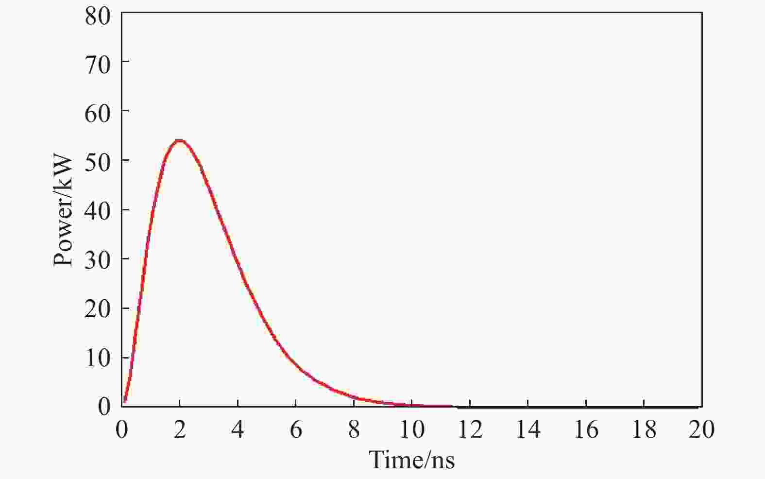
图 4 激光脉冲在时间上的分布
Figure 4. Temporal distribution of a laser pulse
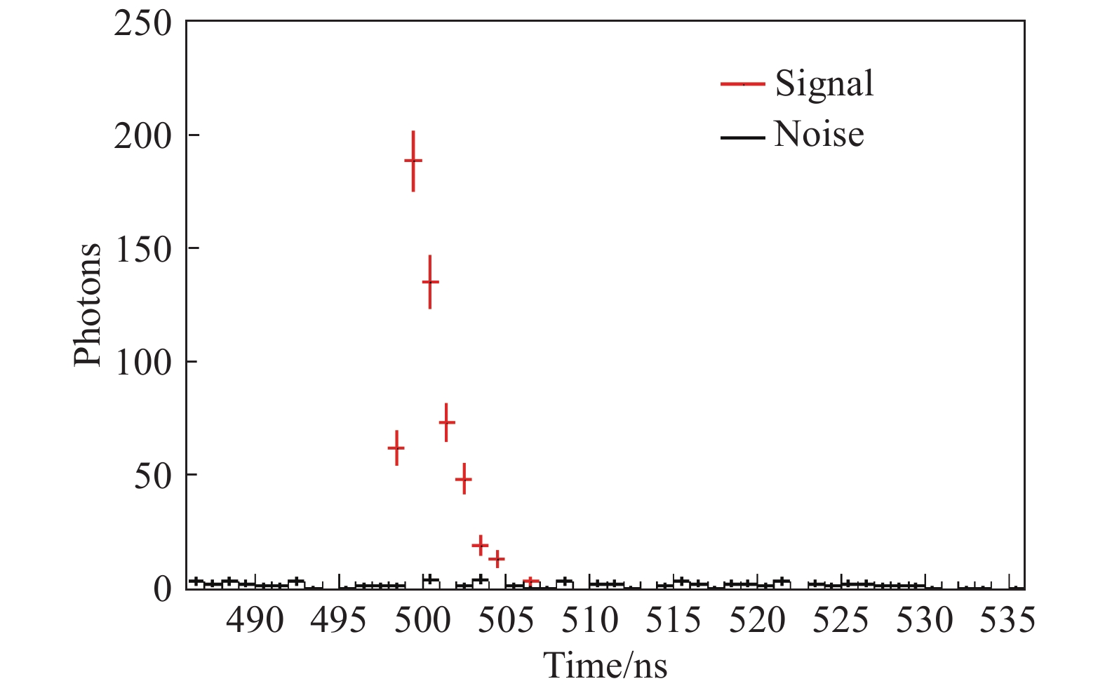
$$s(t) = \left\{\begin{aligned} &\;\;\; {0,} & {t < 0} \\ &{{\left(\frac{t}{\tau }\right)}^2}{{\rm{e}}^{-\frac{t}{\tau}}},&{t\geqslant 0} \end{aligned}\right.,\;\;\tau = \frac{{{\rm{FWHM}}}}{{3.5}}$$ (3) 图5给出了蒙特卡罗模拟探测20 000个回波脉冲的光子计数结果,其中使用的激光脉冲参数与实验装置一致,单像元单脉冲平均光子数0.03,暗计数率20 kHz,背景噪声80 kHz;门控开启时间2 µs,信号出现在0.5 µs处。由图4可知,激光回波脉冲式集中出现在少数相邻区间内,而噪声在整个门控区间内为均匀分布。

图 5 蒙特卡罗仿真20 000激光脉冲的光子计数结果
Figure 5. Photon-counting result of 20 000 laser pulses with Monte Carlo simulation
-
基于搭建的1 064 nm激光探测实验装置,对室外600 m处建筑物进行了凝视探测,发射的激光脉冲重复频率PRF=1 kHz。为了降低背景光与暗计数噪声,在每次探测回波前施加了时间延迟2.5 μs,再开启探测门控4 μs,面阵单光子探测器共采集了20 000帧光子探测数据,用时20 s。
从蒙特卡罗仿真结果可以看出,激光回波信号呈现集中分布,占据的时间区间宽度在10 ns以内,相对于门控时间宽度较短。为此,文中在信号区间估计回波参数,而不在整个门控区间进行全局估计,降低参数估计的复杂度。为了降低噪声的影响,将信号区间扩展至30 ns作为控制区间,从而在回波参数估计中精确估计噪声的贡献。为了避免光子计数起伏引起的虚警事件,以单像元单脉冲单时间区间光子数0.01为阈值,判断门控范围内是否存在回波信号,并将峰值位置附近[−10 ns,20 ns]区间作为参数估计区间。
文中根据公式(2)的响应模型及公式(3)的激光脉冲形状,采用极大似然函数估计方法,逐像元提取目标的反射率与距离信息。单像元上的似然函数可以表示为:
$${\cal{L}}({{T}}|{a_i},{z_i},{\tau _i}) = \mathop \Pi \limits_{k = 1}^N {\lambda _i}({t_k})$$ (4) 式中:
$T{\rm{ = \{ }}{t_1},{t_2},...{t_N}{\rm{\} }}$ 表示像元$i$ 测量的光子到达时间;$N$ 表示信号区间探测的光子数。从公式(4)可以看出,进行一次极大似然函数估计可以同时提取出目标反射率、距离、脉冲宽度等信息,中ROOT/C++工具进行似然函数的最小化求解。图6(a)为目标的照片,图中白线方框标出了成像区域;图6(b)和(c)分别为采用1 000帧和20 000帧数据估计的目标反射率图像,图像分辨率与面阵单光子探测器规模相同。其中1 000帧和20 000帧数据中每个像元平均累积的光子数分别为30.8和601.6,可以看出数据量较少情况下,反射率估计结果的像元间起伏较大;图6(d)和(e)分别为采用1 000帧和20 000帧数据估计的目标距离图像,同样数据量较小的情况下像元间的起伏较大,测距精度较差。
-
在对高速运动目标探测或进行大视场成像时,脉冲累积时间往往有限,导致回波光子的采样数不足。在这种情况下,利用少量光子实现精确图像重构变的较为重要。从逐像元极大似然估计的成像结果可以看出,累积光子数较少时成像精度较低。通常自然图像的像素间具有一定的空间关联,在某种变换下能够进行稀疏表示。文中将利用自然图像的稀疏特性来提升累积光子数较少情况下的成像精度。
文中采用正则化方法,将图像似然函数与空间关联约束函数结合起来,建立代价函数进行图像重构,代价函数的形式为:
$$C({{x}}) = - \ln {\cal{L}}({{s}}|{{x}}) + \lambda R({{x}})$$ (5) 式中:s和x分别为原始图像信号和拟重构的图像信号;
${\cal{L}}({{s}}|{{x}})$ 为图像的似然函数项;$R({{x}})$ 为空间关联约束函数项;$\lambda $ 为正则化系数,用于平衡似然函数项和约束函数项的贡献。通过公式(5),图像重构问题即转化成为代价函数的最小化问题,通过代价函数的最小化求解来实现图像重构。累积光子数较少的情况下,其服从泊松分布,因此采用泊松似然函数作为反射率图像重构的似然函数项。泊松概率密度函数的期望值与方差相同,通过观测的光子数即可建立泊松似然函数。像元测量的光子到达时间主要受发射脉冲抖动、计时精度等因素影响,服从正态分布。为此,采用高斯似然函数作为距离图像估计的似然函数项,高斯分布的均值和方差来自于上节中极大似然估计的结果。为了更好的描述图像的稀疏特性,首先对图像信号进行离散小波变换(DWT),然后计算全变分(TV)作为约束函数[22-23],代价函数进一步可以表示为:
$$C({{x}}) = - \ln {\cal{L}}({{s}}|{{x}}) + \lambda {\left\| {{{{W}}^{\bf{T}}}{{x}}} \right\|_{TV}}$$ (6) 式中:
${{W}}$ 为离散小波变换。Harmany等人证明该问题在数学上是凸问题,具有严格解。文中采用SPRIAL-TAP工具包[17]进行公式(6)中代价函数的最小化求解。由于该图像信号值服从泊松分布,具有非负约束条件,SPRIAL-TAP通过可分离二次规划方法实现了该约束条件下最优化问题的求解。文中利用1 000帧数据的反射率图像和距离图像分别进行正则化图像重构,采用了0.05、0.10、0.15、0.2,4个不同的正则化系数,图7给出了相应的反射率图像重建结果。可以看出,随着
$\lambda $ 的增大,约束函数的贡献也变大,图像变得更为平滑;重构图像相对于原始图像(图6(b))更加清晰,像素间的起伏甚至小于20 000帧数据图像(图6(c))。
图 6 (a) 600 m外目标照片,(b) 1 000帧数据反射率图像,(c) 20 000帧数据反射率图像,(d) 1 000帧数据距离图像,(e) 20 000帧数据距离图像
Figure 6. (a) Object photograph with 600 m away, (b) Intensity image with 1 000 frame data, (c) Intensity image with 20 000 frame data, (d) Range image with 1 000 frame data, (e) Range image with 20 000 frame data
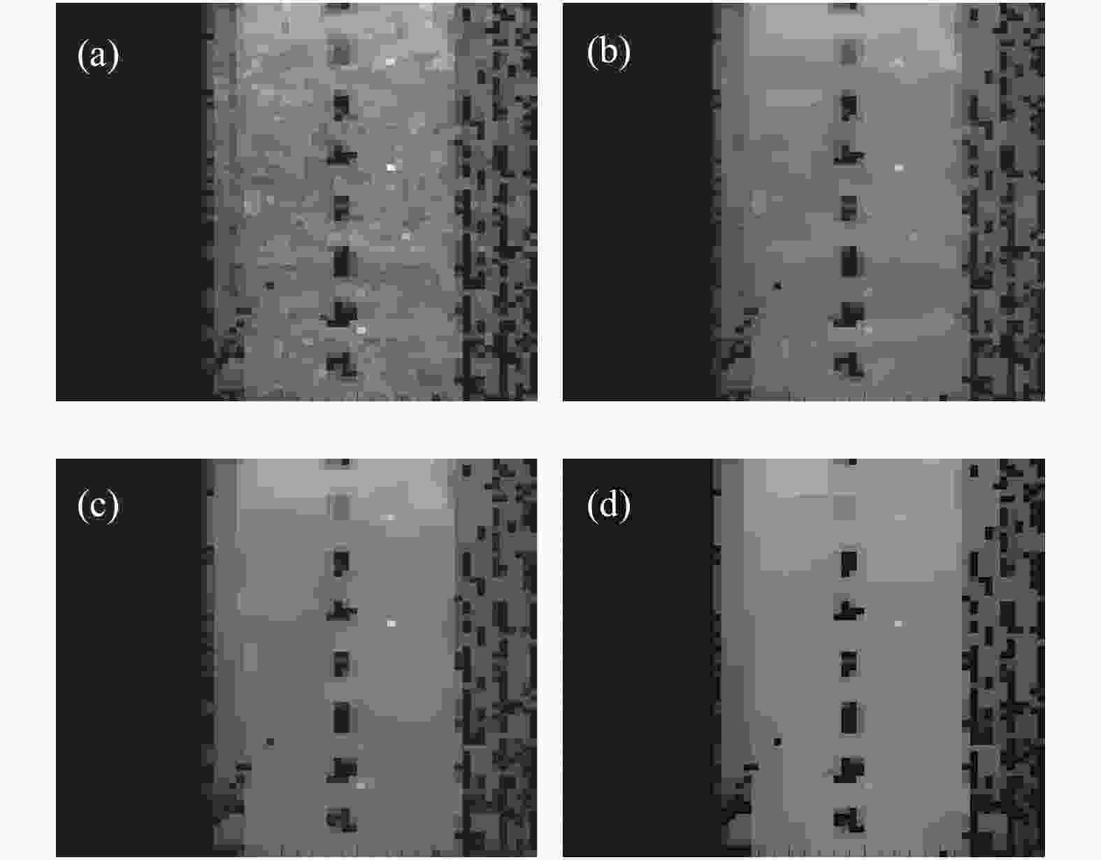
图 7 基于1 000帧数据重构的反射率图像。(a)
$\lambda {\rm{ = 0}}{\rm{.05}}$ ,(b)$\lambda {\rm{ = 0}}{\rm{.10}}$ ,(c)$\lambda {\rm{ = 0}}{\rm{.15}}$ ,(d)$\lambda {\rm{ = 0}}{\rm{.20}}$ Figure 7. Intensity images reconstructed with 1 000 frame data.(a)
$\lambda {\rm{ = 0}}{\rm{.05}}$ , (b)$\lambda {\rm{ = 0}}{\rm{.10}}$ , (c)$\lambda {\rm{ = 0}}{\rm{.15}}$ , (d)$\lambda {\rm{ = 0}}{\rm{.20}}$ 图8给出了正则化系数
$\lambda $ 分别为0.05、0.10、0.15、0.20的距离图像重建结果,由此可以看出像素间起伏逐渐变小,但相对于20 000帧数据距离图像仍存在一定起伏。为了计算正则化方法的距离图像重构精度,以图6(e)为参考分别计算图8中每个距离图像的偏差。
图 8 基于1 000帧数据重构的距离图像。(a)
$\lambda {\rm{ = 0}}{\rm{.05}}$ ,(b)$\lambda {\rm{ = 0}}{\rm{.10}}$ ,(c)$\lambda {\rm{ = 0}}{\rm{.15}}$ ,(d)$\lambda {\rm{ = 0}}{\rm{.20}}$ Figure 8. Range images reconstructed with 1 000 frame data. (a)
$\lambda {\rm{ = 0}}{\rm{.05}}$ , (b)$\lambda {\rm{ = 0}}{\rm{.10}}$ , (c)$\lambda {\rm{ = 0}}{\rm{.15}}$ , (d)$\lambda {\rm{ = 0}}{\rm{.20}}$ $${RMS} = \frac{{\rm{1}}}{N}\sum\limits_{i = 1}^N {{{({z_1} - {z_2})}^2}} $$ (7) 式中:
${z_1}$ 和${z_{\rm{2}}}$ 分别为重建图像和参考图像每个像素的距离值。图8中各图像的RMS分别为0.31、0.31、0.32、0.34,原始图6(d)图像相对于图6(e)的RMS为0.36,因此正则化方法将三维图像的整体成像精度从0.36 m提升至0.31 m。 -
文中利用64×64规模的InGaAs盖革雪崩焦平面阵列作为面阵单光子探测器,搭建了1 064 nm激光主动探测三维成像实验装置,实现了600 m外目标散射回波信号的高灵敏度探测。文中重点讨论了单光子探测成像模型与方法,分析了累积光子数不足情况下的成像精度问题。采用正则化方法进行图像重构,结合了光子探测物理模型及自然图像稀疏先验假设。通过对比表明,正则化方法能够提升反射率与距离图像的重构精度,改善累积光子数不足情况下的图像质量。笔者下一步将开展基于面阵单光子探测器的快速扫描成像研究,从而适应于高速运动目标探测与跟踪、大视场成像等应用。
Photon-counting 3D imaging based on Geiger-mode APD array
-
摘要: 基于盖革APD阵列的激光主动探测系统具有较高的灵敏度、空间分辨率和测距精度,在遥感探测、目标识别等领域具有广泛的应用前景。受探测模式、噪声等因素影响,盖革APD阵列需要大量累积光子探测来实现高精度成像。针对该问题,基于目前国内规模最大的InGaAs盖革APD阵列,搭建了1 064 nm激光探测实验装置,对室外600 m外目标进行了成像。通过分析光子计数物理过程,建立了目标反射率与距离的极大似然估计。结合自然图像稀疏的先验知识,采用正则化图像重构方法,改善了累积光子数较少情况下的成像精度。通过对比,验证了正则化图像重构方法能够抑制光子数涨落引起的参数估计偏差,提升了成像质量。Abstract: Laser detection and ranging system based on Geiger-mode APD (GM-APD) array can achieve very high sensitivity, spatial resolution and ranging precision, which has wide applications in remote sensing, target recognition and so on. Limited by the factors of detection mode and noises, GM-APD usually requires large number of photon detections to carry out high imaging precise. For this problem, firstly a ladar system based on national state-of-the-art InGaAs GM-APD array was set up at a wavelength of 1 064 nm. The system was then used for imaging of a building about 600 m away. The photon detection process on GM-APD was analyzed for the reflection and ranging information extractions with maximum likelihood estimation method. For the condition that only a few photons were detected on a pixel, the prior of natural scene’s spare property was used to improve the imaging precise based on regularized image reconstruction method. Through comparison, it was verified that the regularized method can reduce the estimation error due to photon detection fluctuation, and improve the imaging quality.
-
Key words:
- 3D laser imaging /
- GM-APD array /
- maximum likelihood estimation /
- regularized method
-
图 1 基于面阵探测器的激光脉冲三维成像原理图
Figure 1. Schematic diagram of 3D imaging using laser pulses and array detector
图 2 (a) 原始激光束的光强空间分布,(b) 整形后光束的光强空间分布
Figure 2. (a) Spatial intensity distribution of original laser beam, (b) spatial intensity distribution of laser beam after reshaping
图 5 蒙特卡罗仿真20 000激光脉冲的光子计数结果
Figure 5. Photon-counting result of 20 000 laser pulses with Monte Carlo simulation
图 6 (a) 600 m外目标照片,(b) 1 000帧数据反射率图像,(c) 20 000帧数据反射率图像,(d) 1 000帧数据距离图像,(e) 20 000帧数据距离图像
Figure 6. (a) Object photograph with 600 m away, (b) Intensity image with 1 000 frame data, (c) Intensity image with 20 000 frame data, (d) Range image with 1 000 frame data, (e) Range image with 20 000 frame data
图 7 基于1 000帧数据重构的反射率图像。(a)
$\lambda {\rm{ = 0}}{\rm{.05}}$ ,(b)$\lambda {\rm{ = 0}}{\rm{.10}}$ ,(c)$\lambda {\rm{ = 0}}{\rm{.15}}$ ,(d)$\lambda {\rm{ = 0}}{\rm{.20}}$ Figure 7. Intensity images reconstructed with 1 000 frame data.(a)
$\lambda {\rm{ = 0}}{\rm{.05}}$ , (b)$\lambda {\rm{ = 0}}{\rm{.10}}$ , (c)$\lambda {\rm{ = 0}}{\rm{.15}}$ , (d)$\lambda {\rm{ = 0}}{\rm{.20}}$
图 8 基于1 000帧数据重构的距离图像。(a)
$\lambda {\rm{ = 0}}{\rm{.05}}$ ,(b)$\lambda {\rm{ = 0}}{\rm{.10}}$ ,(c)$\lambda {\rm{ = 0}}{\rm{.15}}$ ,(d)$\lambda {\rm{ = 0}}{\rm{.20}}$ Figure 8. Range images reconstructed with 1 000 frame data. (a)
$\lambda {\rm{ = 0}}{\rm{.05}}$ , (b)$\lambda {\rm{ = 0}}{\rm{.10}}$ , (c)$\lambda {\rm{ = 0}}{\rm{.15}}$ , (d)$\lambda {\rm{ = 0}}{\rm{.20}}$ -
[1] McManamon P. Review of ladar: a historic, yet emerging, sensor technology with rich phenomenology [J]. Optical Engineering, 2012, 51(6): 060901. doi: 10.1117/1.OE.51.6.060901 [2] McCarthy A, Collins R J, Krichel N J, et al. Long-range time-of-flight scanning sensor based on high-speed time-correlated single-photon counting [J]. Applied Optics, 2009, 48(32): 6241−6251. doi: 10.1364/AO.48.006241 [3] Heinrichs R, Aull B F, Marino R M, et al. Three-dimensional laser radar with APD arrays[C]// SPIE, 2001, 4377: 106-118. [4] 谢绍禹, 赵毅强, 王永乐, 等. 基于盖革APD阵列的微扫描激光成像技术[J]. 红外与激光工程, 2018, 47(12): 1206010. doi: 10.3788/IRLA201847.1206010 Xie Shaoyu, Zhao Yiqiang, Wang Yongle, et al. Microscanning laser imaging technology based on Geiger-mode APD array [J]. Infrared and Laser Engineering, 2018, 47(12): 1206010. (in Chinese) doi: 10.3788/IRLA201847.1206010 [5] 王帅, 孙华燕, 赵延仲, 等. 基于光学相控阵的提高APD阵列三维成像分辨率方法[J]. 红外与激光工程, 2019, 48(4): 0406003. doi: 10.3788/IRLA201948.0406003 Wang Shuai, Sun Huayan, Zhao Yanzhong, et al. Method of improving 3D imaging resolution of APD array based on optical phased array [J]. Infrared and Laser Engineering, 2019, 48(4): 0406003. (in Chinese) doi: 10.3788/IRLA201948.0406003 [6] Itzler M A, Jiang X, Entwistle M, et al. Advances in InGaAsP-based avalanche diode single photon detectors [J]. Journal of Modern Optics, 2011, 58(3-4): 174−200. doi: 10.1080/09500340.2010.547262 [7] Marino R M, Davis W R, Rich G C, et al. High-resolution 3D imaging laser radar flight test experiments[C]//SPIE, 2005, 5791: 138-152. [8] Marino R M, Davis W R. Jigsaw: a foliage-penetrating 3D imaging laser radar system [J]. Lincoln Lab J, 2005, 15(1): 23−36. [9] Knowlton R. Airborne ladar imaging research testbed[D].US: MIT Lincoln Laboratory Lexington United States, 2011. [10] Albota M A, Gurjar R S, Mangognia A V D, et al. The airborne optical systems testbed (AOSTB)[R]. US:MIT Lincoln Laboratory Lexington United States, 2017. [11] Clifton W E, Steele B, Nelson G, et al. Medium altitude airborne Geiger-mode mapping LIDAR system[C]//SPIE, 2015, 9465: 946506. [12] 徐正平, 沈宏海, 姚园, 等. 直接测距型无扫描激光主动成像验证系统[J]. 光学 精密工程, 2016, 24(2): 251−259. doi: 10.3788/OPE.20162402.0251 Xu Zhengping, Shen Honghai, Yao Yuan, et al. Scannerless laser active imaging validating system by directly ranging [J]. Optics and Precision Engineering, 2016, 24(2): 251−259. (in Chinese) doi: 10.3788/OPE.20162402.0251 [13] 徐正平, 许永森, 姚园, 等. 凝视型激光主动成像系统性能验证[J]. 光学 精密工程, 2017, 25(6): 1441−1448. doi: 10.3788/OPE.20172506.1441 Xu Zhengping, Xu Yongsen, Yao Yuan, et al. Performance verification of staring laser active imaging system [J]. Optics and Precision Engineering, 2017, 25(6): 1441−1448. (in Chinese) doi: 10.3788/OPE.20172506.1441 [14] 孙剑峰, 姜鹏, 张秀川, 等. 32×32面阵InGaAs Gm-APD激光主动成像实验[J]. 红外与激光工程, 2016, 45(12): 1206006. doi: 10.3788/IRLA201645.1206006 Sun Jianfeng Jiang Peng, Zhang Xiuchuan, et al. Experimental research of 32×32 InGaAs Gm-APD arrays laser active imaging [J]. Infrared and Laser Engineering, 2016, 45(12): 1206006. (in Chinese) doi: 10.3788/IRLA201645.1206006 [15] Buller G, Wallace A. Ranging and three-dimensional imaging using time-correlated single-photon counting and point-by-point acquisition [J]. IEEE Journal of Selected Topics in Quantum Electronics, 2007, 13(4): 1006−1015. doi: 10.1109/JSTQE.2007.902850 [16] McManamon P F, Banks P S, Beck J D, et al. Comparison of flash lidar detector options [J]. Optical Engineering, 2017, 56(3): 031223. doi: 10.1117/1.OE.56.3.031223 [17] Harmany Z T, Marcia R F, Willett R M. This is SPIRAL-TAP: Sparse Poisson intensity reconstruction algorithms—theory and practice [J]. IEEE Transactions on Image Processing, 2012, 21(3): 1084−1096. doi: 10.1109/TIP.2011.2168410 [18] Mertens L, Sonnleitner M, Leach J, et al. Image reconstruction from photon sparse data [J]. Scientific Reports, 2017, 7: 42164. doi: 10.1038/srep42164 [19] Richmond R, Cain S. Direct-detection LADAR systems[C]//Society of Photo-Optical Instrumentation Engineers, 2010. [20] Fouche D G. Detection and false-alarm probabilities for laser radars that use Geiger-mode detectors [J]. Applied Optics, 2003, 42(27): 5388−5398. doi: 10.1364/AO.42.005388 [21] Kim S, Lee I, Kwon Y. Simulation of a Geiger-mode imaging ladar system for performance assessment [J]. Sensors, 2013, 13(7): 8461−8489. doi: 10.3390/s130708461 [22] Kirmani A, Venkatraman D, Shin D, et al. First-photon imaging [J]. Science, 2014, 343(6166): 58−61. [23] Shin D, Xu F, Venkatraman D, et al. Photon-efficient imaging with a single-photon camera [J]. Nature Communications, 2016, 7: 12046. doi: 10.1038/ncomms12046 -

 点击查看大图

计量
- 文章访问数: 1304
- HTML全文浏览量: 442
- PDF下载量: 144
- 被引次数: 0


