


-
激光多普勒测速技术(Laser Doppler Velocity, LDV)利用光波多普勒效应测量目标物体速度,这种非接触、高精度、高动态范围的测速方式在航空航天、电力交通、医疗监测等领域得到广泛应用[1-8]。由于光波频率一般在101~103 THz,远超出目前光电探测器频率响应极限,直接探测光多普勒效应造成的光频移动极其困难。参考光型LDV一般采用光外差探测方式,使用窄线宽激光光源,将激光分为信号光和本振光两路传输,信号光经过频率调制之后从端口输出,由测量物体表面反射或散射后与本振光相干混频,最后通过光电探测器获取混频光信息[9-14]。目前,光频调制主要有声光调制(Acousto-Optic Modulator, AOM)、电光调制(Electro-Optic Modulator, EOM)等方式。其中,声光调制器衍射效率较高,插入损耗一般为1 dB,调制带宽在10~100 MHz之间;电光调制器插损一般为3 dB,调制带宽可达0~10 GHz[15]。
目前,国内外LDV外差探测系统研究多采用声光调制方式。加泰罗尼亚理工大学David Garcia-Vizcaino等人设计双光束、双声光调制器参考光束型LDV系统,在固体目标和流体目标中应用,最大测量速度为3 m/s,测量误差小于1%[16]。国防科技大学的周健等人使用双声光调制技术,对参考光和信号光分别进行移频设计,实现目标低速测量和方向辨别,测速精度优于0.35%[15]。电光调制方式LDV系统也有人研究。约翰霍普金斯大学Utkarsh Sharma等人采用光纤型电光调制器,搭建了全光纤型LDV系统[17]。由上述文献调研可知,大多数LDV系统研究采用声光调制或电光调制方式,但两种方式各有特点,目前尚无文献对两种调频方式进行系统对比研究。
文中首先对AOM和EOM移频方式进行理论分析,结合参考光LDV系统采用简化频率变换分析方法研究频移特性,然后搭建光纤型LDV光路对电动位移平台进行测速实验,最后将实验结果与理论研究结合分析,提出一种新型声电混合调制移频方式,该系统具备高精度测量和速度方向分辨等优点,为后续LDV系统研制设计提供参考。
-
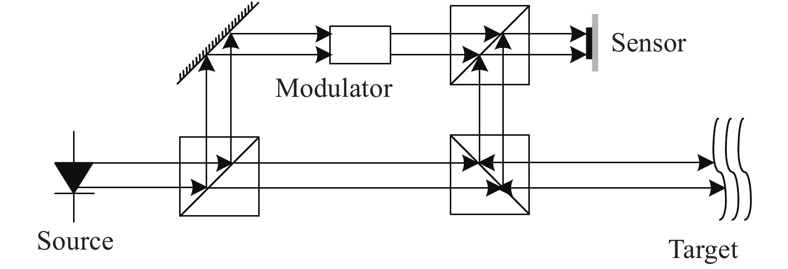
参考光LDV系统光路结构如图1所示,将光源分为参考光和信号光,参考光经调制器进行频率调制,反射信号光经运动目标多普勒频率调制,探测器接收两光路混频信号。下面将研究电光和声光调制器件移频原理。

图 1 参考光激光多普勒测速系统光路结构
Figure 1. Optical path structure of laser Doppler velocity measurement system of reference light
电光调制方式以铌酸锂晶体为例,电光铌酸锂相位调制器结构如图2所示。在调制信号作用下,电光晶体的折射率发生改变,晶体波导中o光和e光经过不同的光程,产生附加相位[18]。

图 2 电光铌酸锂相位调制器结构
Figure 2. Structure of the electro-optic lithium niobate phase modulator
通过相位调制实现信号的频率及相位变化,由于调频和调相实质上最终都是调制相角,写成统一的形式:
$$e\left( t \right) = {A_c}\cos \left( {{\omega _c}t + m\sin {\omega _m}t + {\phi _c}} \right)$$ (1) 式中:
$m\sin {\omega _m}t$ 为电场调制信号。将公式(1)展开,可得:$$e({{t}}) = {A_c}\left[ \begin{array}{l} \cos \left( {{\omega _c}t + {\phi _c}} \right)\cos \left( {m\sin {\omega _m}t} \right) \\ - \sin \left( {{\omega _c}t + {\phi _c}} \right)\sin \left( {m\sin {\omega _m}t} \right) \end{array} \right]$$ (2) 将式中
$\cos \left( {m\sin {\omega _m}t} \right)$ 、$\sin \left( {m\sin {\omega _m}t} \right)$ 两项按贝塞尔函数展开,利用三角函数积化和差公式,可得:$$ \begin{split} e({{t}}) =& {A_c}{J_0}\left( m \right)\cos \left( {{\omega _c}t + {\phi _c}} \right) + {A_c}\displaystyle\sum\limits_{n = 1}^\infty {J_n}\left( m \right)\times\\ &\left[ \cos \left( {{\omega _c} + n{\omega _m}} \right)t + {\phi _c} + {\left( { - 1} \right)^n} \cos \left( {{\omega _c} - n{\omega _m}} \right)t + {\phi _c} \right] \end{split} $$ (3) 由上式可知,在单频正弦波进行相位或频率调制时,其调制波的频谱是由光载频和它两边对称分布的无穷多对边频组成。各边频之间频率间隔是
${\omega _m}$ ,各边频幅度大小${J_n}\left( m \right)$ 由贝塞尔函数决定。声光调制器结构如图3所示。AOM由驱动器提供周期调制电平信号,该信号加载在电声换能器两端,在声光晶体中产生与调制信号频率相同的超声波,该超声波调制声光晶体,使之内部形成等效位相光栅。当进行高重频声波场调制时,使入射光信号产生布拉格衍射,进而使光束能量发生偏转,完成对入射光强度及频率调制[19]。

图 3 声光调制器结构
Figure 3. Structure of the acousto-optic modulator
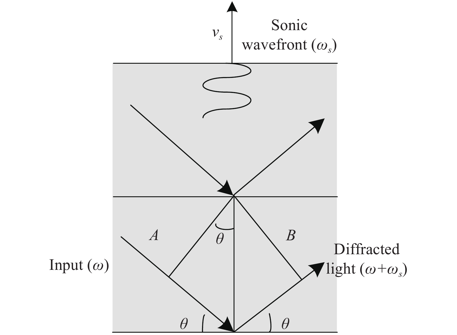
当对驱动器进行高电平直流调制时,驱动器持续周期调制换能器,保持声光调制器内有恒定超声波场,此时AOM仅对入射光产生频率调制,调频过程如图4所示。假设光波沿与水平方向夹角
$\theta $ 的方向入射,则其光场表达式为:$${e_0}\left( {\overrightarrow r ,t} \right) = {E_0}{{\rm e}^{({\rm{j}}{\omega _0}{{t}} - {{\overrightarrow k }_0}\overrightarrow r )}}$$ (4) 超声光场沿如图4中的声光晶体方向传播,其振幅表达式为:
$${e_1}\left( {\overrightarrow r ,t} \right) = {E_1}{{\rm e}^{({\rm{j}}{\omega _1}{{t}} - {{\overrightarrow k }_1}\overrightarrow r )}}$$ (5) 现用超声波场对光场进行调制,可得:
$$e\left( {\overrightarrow r ,t} \right) = {e_0}\left( {\overrightarrow r ,t} \right) \times {e_1}\left( {\overrightarrow r ,t} \right) = {E_0}{E_1}{{\rm e}^{[{\rm{j}}({\omega _0} + {\omega _1}){{t}} - ({{\overrightarrow k }_0} + {{\overrightarrow k }_1})\overrightarrow r ]}}$$ (6) 由上式可知,入射光经布拉格衍射后频率变为
${\omega _0} + {\omega _s}$ 。此时,声光调制器仅具有移频功能,且频率单一变化。光纤型铌酸锂声光调制器因固定入射光和出射光位置,衍射角度确定,因此具有频移量不变的特性。
图 4 声光调制器频率调制机理
Figure 4. Diagram of frequency modulation of acousto-optic modulator
-
采用频率简化变换分析方法对两种移频方式的频率变换进行研究,包括静止目标和运动目标。
依照铌酸锂相位调制器移频特性对外差式光多普勒频移进行研究,将通过EOM调制一端作为信号光输出至参考屏,将未经调制一端作为参考光输出至探测器,在探测器上将反射信号光与参考光进行差频测量。为了简化分析过程,仅对信号频率变化进行研究,EOM调制频率仅考虑到2倍频率间隔。现假设光频信号频率为f0
,EOM调制频率为fs,光源、参考屏及探测器三者置于同一条直线上,垂直照射。光源保持静止,参考屏向光源进行相向和相反运动。由于光多普勒效应,信号光在经运动参考屏反射后,反射信号光会产生频率变化。现假设多普勒频移为fd,经研究不同运动方向反射信号光频率可得: $$ {f_{t1}} = \left\{ \begin{array}{l} {f_0} + {f_d} \\ {f_0} + {f_s} + {f_d} \\ {f_0} + {f_s} - {f_d} \\ {f_0} + 2{f_s} + {f_d} \\ {f_0} + 2{f_s} - {f_d} \end{array} \right.,\;{f_{t2}} = \left\{ \begin{array}{l} {f_0} - {f_d} \\ {f_0} + {f_s} - {f_d} \\ {f_0} - {f_s} - {f_d} \\ {f_0} + 2{f_s} - {f_d} \\ {f_0} - 2{f_s} - {f_d} \end{array} \right. $$ (7) 式中:ft1为相向运动信号光频率;ft2为相反运动信号光频率,现与参考光f0进行混频(忽略和频、倍频信息),可得:
$$ {f_{t1}} - {f_{\rm{0}}} = \left\{ \begin{array}{l} {f_d} \\ {f_s} + {f_d} \\ {f_s} - {f_d} \\ 2{f_s} + {f_d} \\ 2{f_s} - {f_d} \end{array} \right.,\;\;{f_{t2}} - {f_{\rm{0}}} = \left\{ \begin{array}{l} - {f_d} \\ {f_s} - {f_d} \\ - {f_s} - {f_d} \\ 2{f_s} - {f_d} \\ - 2{f_s} - {f_d} \end{array} \right. $$ (8) 对比混频信号
${f_{t1}} - {f_{\rm{0}}}$ 和${f_{t2}} - {f_{\rm{0}}}$ 可知,两种混频信号的频率分量一致,都包含${f_d}$ ,${f_s} \pm {f_d}$ ,$2{f_s} \pm {f_d}$ 五种频率分量。由此可见,采用铌酸锂相位调制器的单移频外差探测方式,虽能测量调制频率及多普勒频移大小,但无法辨别多普勒频移方向及物体运动方向。现将光纤型铌酸锂声光调制器置于外差探测光路中,研究物体运动对其频率输出的影响,与EOM相同,光源、探测器保持静止,参考屏进行相向和相反运动。现假设多普勒频移为fd,相向运动信号ft1,相反运动信号ft2,可得:
$${f_{t1}} - {f_{\rm{0}}} = {f_0} + {f_s} + {f_d} - {f_0} = {f_s} + {f_d}$$ (9) $${f_{t2}} - {f_{\rm{0}}} = {f_0} + {f_s} - {f_d} - {f_0} = {f_s} - {f_d}$$ (10) 由公式(10)、(11)可知,不同运动方向产生的差频信号频率不同,其中相向运动差频信号
${f_{t1}} - {f_{\rm{0}}} = $ $ {f_s} + {f_d}$ ,相反运动差频信号${f_{t2}} - {f_{\rm{0}}} = {f_s} - {f_d}$ 。因此,声光调制器移频型外差探测方式可通过不同差频信号分辨运动物体速度值和方向。对两种调频方式进行频率变换分析研究发现两种方式各有特点,现提出一种新型频率调制方式,即声电并联调制。
-
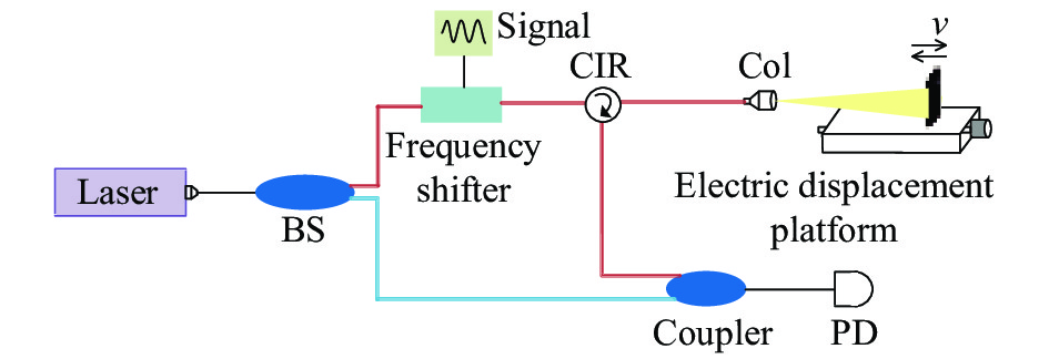
通过上述理论研究,EOM和AOM移频方式不同,在参考光型LDV系统中会产生不同移频结果。为验证上述两种移频器件外差探测结果,现按图5搭建了激光多普勒测速系统的光路。其中,单频光纤激光器,中心波长1550 nm,线宽3 kHz;铌酸锂电光调制器,中心波长1550 nm,调制带宽10 GHz,插入损耗3 dB;声光调制器,中心波长1550 nm,中心频率100 MHz,插入损耗1 dB;光电探测器,最大探测带宽150 MHz;使用电控位移平台作为速度源,最大位移速度为40 mm/s。经示波器采集时域信号,采用FFT和Goertzel频谱细化算法得到混频信号的频率信息。

图 5 参考光激光多普勒测速系统光路结构
Figure 5. Optical path structure of laser Doppler velocity measurement system of reference light
-
铌酸锂移相器外加5 MHz正弦信号,示波器采样速率25 MSa/s,采样时间10 ms。为降低测量误差,采用多次测量方式。在位移平台静止的状态下,经计算得出全频域范围内的混频信号。由表1中数据可看出频率信号包含5 MHz和10 MHz的信号,由图6可看出两种频率成分信号强度的对比,此结果与此前分析一致。因示波器采样速率为25 MSa/s,根据奈奎斯特采样定理,理论上最大探测到12.5 MHz的频率信号,所以频谱中没有3倍频及以上频率成分。
表 1 电光调制型静止条件下的外差频率
Table 1. Electro-optic modulation heterodyne frequency under static conditions
Number Frequency 1/Hz Frequency 2/Hz 1 5000210 9990788 2 4999924 9990501 3 5000019 9990501 4 4999828 9990788 5 4999828 9990692 Average frequency 4999962 9990654 
图 6 电光调制型静止目标的外差信号频谱
Figure 6. Spectrum of heterodyne signal of electro-optic modulation static target
现将位移平台速度调整为3 mm/s,分为相向运动和相反运动。进行多次测量,降低测量误差,相向运动和相反运动频率计算结果见表2。由表中数据可知,相向运动和相反运动均产生五种频率值,分别为多普勒效应产生的频率f1,信号频率叠加多普勒频率f2、f3, 2倍信号频率叠加多普勒频率f4、f5。实际频谱图如图7所示,在信号频率5 MHz和2倍频信号频率10 MHz处均出现对称频率叠加多普勒频率。同时,表2中经对称信号频率差求多普勒频率,单次测量可得到至少三组多普勒频率值(与采样速率与倍频幅度相关)。由计算结果可知,三组多普勒频率值相对误差均小于20 Hz,对应目标速度误差小于15.5 μm/s。对比相对运动和相反运动频率值,频率符号和频率成分相同,因此无法判断运动方向,频率值差异是由电动平台前后运动标称速度与实际速度不同产生,符合前述理论研究。
表 2 电光调制型目标速度3 mm/s时的外差频率
Table 2. Heterodyne frequency of electro-optic modu-lation target at 3 mm/s velocity
Direction
frequency/HzRelative Opposite f1 4578 5245 f2 4995414 4994774 f3 5004583 5005264 f4 9995433 9994777 f5 10004575 10005252 (f3−f2)/2 4584 5245 (f5−f4)/2 4571 5237 
图 7 电光调制型目标速度3 mm/s时的外差频谱。 (a) 相向运动;(b)相反运动
Figure 7. Heterodyne spectrum of electro-optic modulation target at 3 mm/s velocity. (a) Relative movement; (b) Opposite movement
-
将铌酸锂声光调制器替换光路中的铌酸锂移相器,其余光路不变。因AOM器件的特性,其超声场频率由驱动器决定且唯一,笔者实验所用AOM中心频率为100 MHz,示波器采样率为250 MSa/s,采样时间为1 ms。表3为位移平台静止状态下采集的多组外差频率值,由表中数据可知,静止条件下,AOM外差探测光路所得混频信号频率值为100006893 Hz,与标称频率值不同,需对实际频率变化进行校正。由图8中混频信号时域图像和频域图像可知,混频后信号只有一种频率成分,与前述移频特性研究一致。
表 3 声光调制型静止目标的外差频率
Table 3. Heterodyne frequency value of acousto-optic modulation static target
Number Frequency/Hz 1 100006938 2 100006938 3 100006938 4 100006819 5 100006819 Average frequency 100006893 
图 8 声光调制型静止目标的外差信号频谱
Figure 8. Frequency spectrum diagram of heterodyne signal of acousto-optic modulation static target
将位移平台速度设为3 mm/s,分为相向运动和相反运动。经多次测量和计算,频率数据见表4。由表中数据及图9可知,与静止状态相同,外差探测混频后频率成分唯一,为信号频率叠加多普勒效应产生的频率变化。对比相向和相反运动频率数据可知,位移平台相向运动时,外差频率平均值为−4795 Hz,位移平台相反运动时,外差频率平均值4312 Hz。
表 4 声光调制型目标速度3 mm/s时的外差频率
Table 4. Heterodyne frequency of acousto-optic modu-lation target at 3 mm/s velocity
Direction
frequency/HzRelative Opposite f1 100002646 100009799 f2 99999666 100012302 f3 100004077 100011349 f4 100003123 100012302 f5 100000978 100010276 Average frequency 100002098 100011205 fd=f−f0 −4795 4312 
图 9 声光调制型目标速度3 mm/s时的外差频谱。(a)相向运动;(b)相反运动
Figure 9. Heterodyne spectrum of acousto-optic modulation target at 3 mm/s velocity. (a) Relative movement; (b) Opposite movement
由此可知,AOM调制LDV系统可通过频率变化实现运动目标方向的判定。但由理论研究可知,相向运动时,混频信号频率值大于信号调制频率,相反运动时则相反,实际所得结果与理论研究相反。后经研究发现,AOM进行光束耦合时,不同厂家在1级或−1级衍射位置选择会有不同,文中实验所用AOM即为−1级衍射位置耦合,所以与理论分析结论相反。由表4中多次测量数据可知,多普勒频率平均值与电光调制基本一致,但多次测量数据方差较大。
经上述对比研究,激光多普勒测速系统两种调制方式会产生不同的移频特性,具体对比见表5所示,电光调制方式测速精度因多频率互相校正,相对误差较小,在文中搭建系统中,可实现多普勒频率值相对误差均小于20 Hz,对应目标速度误差小于15.5 μm/s,随着更多频率参与校正可进一步提高精度;电光调制频率变化范围较大,增大速度测量动态范围,声光调制频率变化范围较小,且调制频率较高,测量低速目标时,精度较低;电光调制多普勒频率变化对称分布,速度方向模糊,声光调制可分辨目标速度方向,且插损较小。
表 5 两种调制方式移频特性对比
Table 5. Comparison of frequency shift characteristics of two modulation methods
Modulation Relative error Direction Dynamic range Insertion loss/dB Connection Electro-optic Smaller Ambiguity Full speed range −3 Fiber Acousto-optic Bigger Distinguishable High speed −1 Fiber -
经过上述对声光和电光两种移频方式的分析和实验验证,现提出一种声电混合调制外差系统,搭建实验系统如图10所示。将AOM和EOM并联分别接入信号光端和参考光端,AOM插入损耗较小,降低了信号衰减。其中,AOM中心频率为100 MHz,EOM调制频率5 MHz,示波器采样率250 MSa/s,采样时间1 ms,目标平台速度5 mm/s。
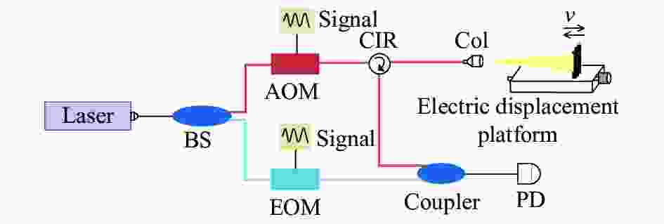
图 10 声电混合调制激光多普勒测速系统光路结构
Figure 10. Optical path structure of the acousto-electric hybrid modulation laser Doppler velocity measurement system
实验结果如图11所示,为增强对比效果,在系统出射端口增大了反射率,因此差频后产生了极大声光和电光混合调制信号,其中中心主峰是声光调制产生的频率变化,两端分别产生对称电光调制频率旁瓣,最大可有三倍频率旁瓣。对比图11(a)、(b),目标与探测器相对运动时多普勒效应产生的频率移动在主频率左侧,相反运动时多普勒效应产生的频率移动在主频率右侧,且多级旁瓣规律相同。由表6频率数据,一次测量过程中,通过声光主频率移动和电光多级频率移动得到至少三组多普勒频率的变化值,不同运动方向产生的频率变化符号相反,三组频率数据误差小于30 Hz,对应目标速度误差小于23.3 μm/s。文中系统综合声光和电光调制的优势,能实现多次精确测量运动目标的速度和方向,消除多种测量误差,频率调制扩大了速度测量的动态范围。

图 11 声电混合调制型目标速度5 mm/s时的外差频谱。(a)相向运动;(b)相反运动
Figure 11. Heterodyne spectrum of acousto-electric hybrid modulation target at 5 mm/s velocity. (a) Relative movement; (b) Opposite movement
表 6 声电混合调制型运动目标的外差频率
Table 6. Heterodyne frequency of acousto-electric hybrid modulation moving target
Direction
frequency/HzRelative Opposite f11 94997525 95011901 f12 95005691 95005798 f21 99997520 100011897 f22 100005686 100005793 f31 104997515 105011892 f12-f11 −8166 6103 f21-f22 −8166 6104 f31-f32 −8166 6080 -
文中对LDV系统常用EOM和AOM频率调制器的移频原理进行研究,对比两种移频方式频率变化特性。搭建全光纤型LDV系统光路,采用光纤型铌酸锂电光调制器和光纤型铌酸锂声光调制器进行频率调制,对电动位移平台进行速度测量,研究实际多普勒信号的频率变化。结果表明,电光调制LDV系统的多频率特性可降低测量相对误差,且速度测量动态范围较大,但该系统会造成目标速度模糊。声光调制型LDV系统因光耦合方式与光频相关,在测速过程中可分辨目标速度方向,但动态范围较小。综合研究两种调制方式,提出一种新型声电混合调制移频方式,实现单次测量即可获取多组多普勒频率变化数据,且可分辨运动目标的速度方向,三组频率数据误差小于30 Hz,对应目标速度误差小于23.3 μm/s。文中从理论和实验对比验证EOM和AOM两种调制方式LDV系统的性能参数和系统特点,为之后高性能LDV系统设计及移频器件选用提供支持和依据。
Frequency shift characteristics of laser Doppler effect
-
摘要: 为了提高激光多普勒测速系统的性能,增强系统与应用场景适配性,文中对比电光和声光两种主要移频器件的特点,从器件移频原理出发,提出了简化频率变换关系的分析方法,从理论上研究激光多普勒测速系统中两种器件产生的移频特性,搭建铌酸锂电光调制和声光移频全光纤激光测速系统链路,将测试频率特征与理论特征进行对比研究,提出一种新型声电混合调制激光多普勒测速系统。结果表明,该新型系统兼具声光移频测速系统可测量运动目标运动方向、运动速度,完成电光调制测速系统多频率校正的特点,频率测量相对误差较小,动态范围大。通过研究两种移频方式对频率特性,为设计高性能激光多普勒测速系统提供了理论和实验支撑。Abstract: In order to improve the performance of the laser Doppler velocimetry system and enhance the adaptability of the system to application scenarios, the characteristics of the two main frequency shift devices of electro-optic and acousto-optic were compared. Starting from the principle of frequency shifting of devices, a simplified method of analyzing frequency transformation relations was proposed. The frequency shift characteristics of the two devices in the laser Doppler velocimetry system was theoretically studied, all-fiber laser velocimetry system link of a lithium niobate electro-optic modulation and acousto-optic frequency shift were bulit. The test frequency characteristics and the theoretical characteristics was compared. A new type of acousto-electric hybrid modulation laser Doppler velocity measurement system was proposed. The results show that the new system has the advantages that the acousto-optic frequency shift speed measurement system can measure the movement direction and speed of the moving target, and accomplish the multi-frequency correction of electro-optic modulation speed measurement system, the relative error of frequency measurement is small, and the dynamic range is large. By studying the frequency characteristics of the two frequency shifting methods, it provides theoretical and experimental support for the design of high-performance laser Doppler velocity measurement systems.
-
图 1 参考光激光多普勒测速系统光路结构
Figure 1. Optical path structure of laser Doppler velocity measurement system of reference light
图 2 电光铌酸锂相位调制器结构
Figure 2. Structure of the electro-optic lithium niobate phase modulator
图 5 参考光激光多普勒测速系统光路结构
Figure 5. Optical path structure of laser Doppler velocity measurement system of reference light
图 6 电光调制型静止目标的外差信号频谱
Figure 6. Spectrum of heterodyne signal of electro-optic modulation static target
图 7 电光调制型目标速度3 mm/s时的外差频谱。 (a) 相向运动;(b)相反运动
Figure 7. Heterodyne spectrum of electro-optic modulation target at 3 mm/s velocity. (a) Relative movement; (b) Opposite movement
图 8 声光调制型静止目标的外差信号频谱
Figure 8. Frequency spectrum diagram of heterodyne signal of acousto-optic modulation static target
图 9 声光调制型目标速度3 mm/s时的外差频谱。(a)相向运动;(b)相反运动
Figure 9. Heterodyne spectrum of acousto-optic modulation target at 3 mm/s velocity. (a) Relative movement; (b) Opposite movement
图 10 声电混合调制激光多普勒测速系统光路结构
Figure 10. Optical path structure of the acousto-electric hybrid modulation laser Doppler velocity measurement system
图 11 声电混合调制型目标速度5 mm/s时的外差频谱。(a)相向运动;(b)相反运动
Figure 11. Heterodyne spectrum of acousto-electric hybrid modulation target at 5 mm/s velocity. (a) Relative movement; (b) Opposite movement
表 1 电光调制型静止条件下的外差频率
Table 1. Electro-optic modulation heterodyne frequency under static conditions
Number Frequency 1/Hz Frequency 2/Hz 1 5000210 9990788 2 4999924 9990501 3 5000019 9990501 4 4999828 9990788 5 4999828 9990692 Average frequency 4999962 9990654  下载: 导出CSV
表 2 电光调制型目标速度3 mm/s时的外差频率
Table 2. Heterodyne frequency of electro-optic modu-lation target at 3 mm/s velocity
Direction
frequency/HzRelative Opposite f1 4578 5245 f2 4995414 4994774 f3 5004583 5005264 f4 9995433 9994777 f5 10004575 10005252 (f3−f2)/2 4584 5245 (f5−f4)/2 4571 5237
下载: 导出CSV
表 3 声光调制型静止目标的外差频率
Table 3. Heterodyne frequency value of acousto-optic modulation static target
Number Frequency/Hz 1 100006938 2 100006938 3 100006938 4 100006819 5 100006819 Average frequency 100006893
下载: 导出CSV
表 4 声光调制型目标速度3 mm/s时的外差频率
Table 4. Heterodyne frequency of acousto-optic modu-lation target at 3 mm/s velocity
Direction
frequency/HzRelative Opposite f1 100002646 100009799 f2 99999666 100012302 f3 100004077 100011349 f4 100003123 100012302 f5 100000978 100010276 Average frequency 100002098 100011205 fd=f−f0 −4795 4312
下载: 导出CSV
表 5 两种调制方式移频特性对比
Table 5. Comparison of frequency shift characteristics of two modulation methods
Modulation Relative error Direction Dynamic range Insertion loss/dB Connection Electro-optic Smaller Ambiguity Full speed range −3 Fiber Acousto-optic Bigger Distinguishable High speed −1 Fiber
下载: 导出CSV
表 6 声电混合调制型运动目标的外差频率
Table 6. Heterodyne frequency of acousto-electric hybrid modulation moving target
Direction
frequency/HzRelative Opposite f11 94997525 95011901 f12 95005691 95005798 f21 99997520 100011897 f22 100005686 100005793 f31 104997515 105011892 f12-f11 −8166 6103 f21-f22 −8166 6104 f31-f32 −8166 6080
下载: 导出CSV
-
[1] Chen Hongjiang, Nie Xiaoming, Wang Mengcheng. Vehicle integrated navigation system based on two dimensional laser Doppler velocimeter [J]. Infrared and Laser Engineering, 2018, 47(12): 1217008. (in Chinese) doi: 10.3788/IRLA201847.1217008 [2] Garg P, Nasimi R, Ozdagli A, et al. Measuring transverse displacements using unmanned aerial systems laser Doppler vibrometer (UAS-LDV): Development and field validation [J]. Sensors, 2020, 20(21): 6051. doi: 10.3390/s20216051 [3] Fang Yuanqi, Li Lin, Zhong Liang, et al. Experimental study of the flow fields of the impinging jet flames using Laser Doppler Velocimetry(LDV) [J]. Journal of Experiments in Fluid Mechanics, 2019, 33(1): 79-87. (in Chinese) [4] Lal A, Aranchuk S, Doushkina V, et al. Advanced LDV instruments for buried landmine detection[C]//Proceedings of SPIE the International Society for Optical Engineering, 2006, 6217: 621715. [5] Li Y, Zhang X, Zhai G, et al. LDV measurements of particle velocity distribution in an annular stripper [J]. Chinese Journal of Chemical Engineering, 2019, 27(10): 2293-2303. doi: 10.1016/j.cjche.2019.03.016 [6] Liu D M, Zhao Y Z, Zuo Z G. Experimental research on flow field in the draft tube of pump turbines based on LDV [J]. IOP Conference Series: Earth and Environmental Science, 2019, 240(7): 72012-72030. [7] 匡泽远. 基于双频光纤光栅激光器的多普勒测速仪应用研究[D]. 暨南大学, 2016. Kuang Z Y. Research on fiber-optic Doppler velocimeter based on a dual-polarization fiber grating laser[D]. Guangzhou: Jinan University, 2016. (in Chinese) [8] Sun C, Ge T, Li S, et al. 53.3 W Visible-waveband extra high power supercontinuum all-fiber laser [J]. IEEE Photonics Journal, 2016, 8(6): 1504407. [9] Liu Fan, Jin Shilong. Frequency analysis technology in laser Doppler velocimeter [J]. Infrared and Laser Engineering, 2012, 41(6): 1462-1470. (in Chinese) doi: 10.3969/j.issn.1007-2276.2012.06.012 [10] Hu Shuling, Li Jun, Huang Xin, et al. Study on autocorrelation detection based on laser Doppler velocity radar [J]. Semiconductor Optoelectronics, 2017, 38(2): 278-282. (in Chinese) [11] Liu Bo, Cao Chagndong, Sui Xiaolin, et al. Experiment of laser coherence Doppler velocimetry [J]. Laser & Infrared, 2018, 48(12): 1486-1490. (in Chinese) doi: 10.3969/j.issn.1001-5078.2018.12.006 [12] Rodriguez R, Murzyn F, Aubry J, et al. An innovative LDV data processing method for statistical error corrections. Application to homogeneous and non-homogeneous seeding [J]. Flow Measurement & Instrumentation, 2018, 60(8): 67-77. [13] Nie Yanju, Meng Zhaokui, Hu Shuling, et al. Frequency domain adaptive threshold detection for laser Doppler velocimetry [J]. Infrared and Laser Engineering, 2016, 45(4): 0406002. (in Chinese) doi: 10.3788/irla201645.0406002 [14] Fan Zhe, Zhang Chunxi, Niu Yanxiong, et al. Impact of photodetector's nonlinear response on coherent laser Doppler speedometer [J]. Infrared and Laser Engineering, 2014, 43(7): 2103-2107. (in Chinese) doi: 10.3969/j.issn.1007-2276.2014.07.011 [15] Zhou Jian, Wei Guo, Long Xingwu. Research on direction discrimination and low-speedmeasurement for laser Doppler velocimeter [J]. Infrared and Laser Engineering, 2012, 41(3): 632-638. (in Chinese) doi: 10.3969/j.issn.1007-2276.2012.03.017 [16] David Garcia-Vizcaino, Federico Dios, Jaume Recolons, et al. One-wavelength two-component laser Doppler velocimeter system for surface displacement monitoring [J]. Optical Engineering, 2008, 47(12): 123606. doi: 10.1117/1.3050421 [17] Sharma U, Chen G, Kang J U, et al. Fiber optic confocal laser Doppler velocimeter using an all-fiber laser source for high resolution measurements [J]. Optics Express, 2005, 13(16): 6250-6258. doi: 10.1364/OPEX.13.006250 [18] 周自刚. 光电子技术基础[M]. 电子工业出版社, 2015. Zhou Zigang. Fundamentals of Optoelectronics[M]. Beijing: Publishing House of Electronics Industry, 2015. (in Chinese) [19] Shang Jianhua, Ren Lihong, Xu Haiqin, et al. Heterodyne laser Doppler vibrometer based on Doppler acousto-optic frequency shifters [J]. Acta Photonica Sinica, 2012, 41(10): 1149-1155. (in Chinese) doi: 10.3788/gzxb20124110.1149 -

 点击查看大图
计量
- 文章访问数: 407
- HTML全文浏览量: 177
- PDF下载量: 70
- 被引次数: 0


