


-
Hypersonic vehicles can complete specific tasks while traveling at hypersonic speeds (at Mach numbers of 5 or above)[1]. Long gliding flights are possible in near space (at 20–100 km). These vehicles are expected to be deployed widely in the future[2, 3] owing their ability to fly at high speeds, respond rapidly in combat situations, cause significant damages, strong maneuvering, and penetrate effectively[4-5]. However, the reliability of hypersonic vehicles is limited due to the lack of effective autonomous navigation methods, which are required for functions such as high-speed cruising, high-load maneuvers, and penetration, along with encountering highly intense confrontational situations[6].
Celestial navigation is an autonomous navigation method that utilizes star sensors to detect celestial bodies and obtain star maps from which navigation information, including positions, speeds, and attitudes of carriers, can be acquired[7]. Hence, celestial navigation is based on optical observations of star tracker sensors. However, because hypersonic vehicles travel at high Mach numbers in near space, the data collected by optical sensors are influenced by factors such as shock waves outside the vehicles and turbulence fields near the windows[8-9]. Consequently, the imaging targets tend to be distorted and blurred, while jittering and energy attenuation can occur. These aero-optical effects directly influence star map acquisition and celestial navigation solutions[10-12]. Therefore, to promote the application of celestial navigation in hypersonic vehicles, the effects of shock waves on beam deflection must be understood and corrected.
The occurrence of shock waves over hypersonic vehicles is inevitable. Research has shown that small and large shock wave structures form at a convective Mach numbers above 0.7 and 1.2, respectively[13]. Furthermore, most hypersonic vehicles in the United States and Russia have waverider designs [14]. Therefore, the heads of the vehicles have sharp wedges, which induce full shock wave’s structure[15-16]. Higher Mach numbers result in stronger effects of the shock waves[17]. For example, the cross-sections of the main bodies of X-43A and X-51A (developed in the United States) are wedge-shaped. Thus, the effects of wedge-shaped shock waves must be considered during the collection and calibration of star maps for navigation.
One important property of a shock wave is that it can create a curved surface with almost zero thickness and cause dramatic state changes in a continuous medium. In addition, it causes the physical properties (e.g., density, speed, pressure, and temperature) of the media in front of and behind the curved surface to differ considerably[18]. Thus, it causes the deflection of starlight.
Early-stage research on shock wave structures was based on infinitely long flat plates. Many studies were based on the assumption that the carrier in the high-speed flow field is an infinitely long flat plate with a sharp leading edge. Kendall provided a rapid method to calculate the slopes of the shock wave surfaces using this assumption[19]. Garvine studied shock wave propagation models[20], and Butler proposed a method for conducting numerical simulations involving infinitely long plates[21]. Yin et al. classified shock waves caused by pointed and blunt bodies and established a basic model of beam deflection due to shock waves[22]. The stability of the hypersonic shock layer (velocity, temperature, density, and pressure) had been calculated[23]. Nevertheless, these studies did not address problems such as the propagation of measurement errors. Subsequent research in China focused on shock wave structures around conical bodies and their effects[24]. Nevertheless, there are few studies on beam deflection due to wedge-shaped shock waves and the resulting error propagation. That would be the key to control the error of real-time deflection correction.
This paper examined an analytical algorithm for the modeling of wedge-shaped shock waves based on aero-optical theories (Section 1). Next, an ideal beam deflection model and a shock wave measurement error propagation model were established. A quantitative correction model of beam deflection due to shock waves over hypersonic vehicles was constructed (Section 2). The relation between the Mach number and shock wave angles and density variations were calculated. Based on the simulation results, the shock wave angle measurement errors propagation model and their effects on beam deflection were analyzed and confirmed (Section 3). A reference basis for extending the starlight navigation to the hypersonic vehicle can be afforded.
-
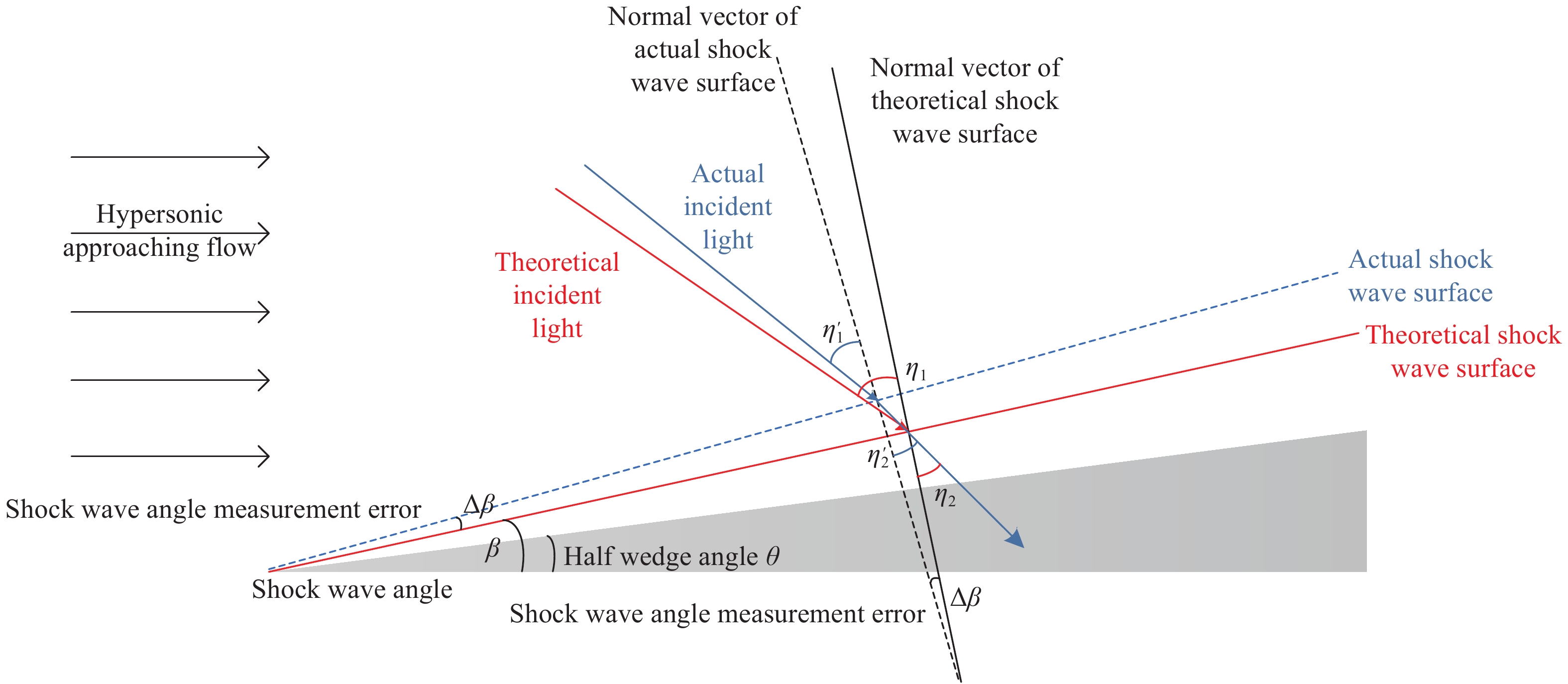
By denoting the half wedge angle of the wedge as
$\theta $ and the shock wave angle as$\;\beta $ (Fig.1), the density of hypersonic approaching flow above and under the shock wave surface as$\;{\rho _1}$ and$\;{\rho _2}$ respectively, the key parameters$\;\beta $ and${{{\;\rho _2}} / {{\rho _1}}}$ can be calculated as follows[25]: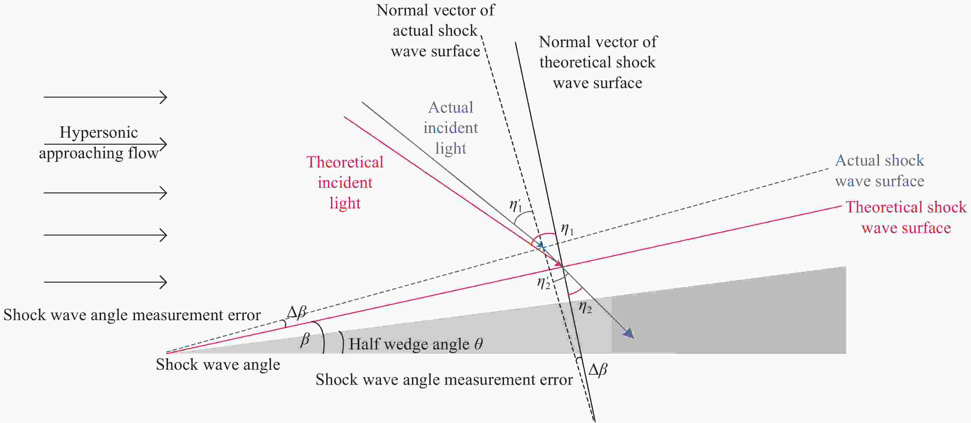
Figure 1. Schematic of wedge-shaped shock waves and beam deflection
$$\tan \theta = \dfrac{{(M_1^2{{\sin }^2}\;\beta - 1)\cot \;\beta }}{{M_1^2\left(\dfrac{{K + 1}}{2} - {{\sin }^2}\;\beta \right) + 1}}$$ (1) $$\dfrac{{{\rho _2}}}{{{\rho _1}}} = \dfrac{{(K + 1)M_1^2{{\sin }^2}\;\beta }}{{2 + (K - 1)M_1^2{{\sin }^2}\;\beta }}$$ (2) where,
${M_1}$ is the Mach number of the approaching flow and$K$ is a constant. In this section, an analytical algorithm model is presented to solve the wedge shock angle derived from Eq. (1).When
$\zeta = \cot \;\beta $ and${\sin ^2}\;\beta = \dfrac{1}{{1 + {\zeta ^2}}}$ , Eq. (1) can be converted into a linear expression as follows:$$ \begin{split} &{\zeta ^3} + \left[ {\left(M_1^2\dfrac{{K + 1}}{2} + 1\right)\tan \theta } \right]{\zeta ^2} + (1 - M_1^2)\zeta +\\ &\;\;\;\;\;\; \left(M_1^2\dfrac{{K - 1}}{2} + 1\right)\tan \theta = 0 \end{split} $$ (3) The post-wave Mach numbers of hypersonic wedge shock waves are greater than 1. Therefore, given a known Mach number of the inlet flow,
${M_1}$ , and a known half wedge angle,$\theta $ , the above cubic equation with one unknown$\zeta $ can be solved analytically[26] as follows:$$\begin{array}{l} \zeta = 2\sqrt { - \dfrac{p}{3}} \cos \left( {\dfrac{\phi }{3}} \right) - \dfrac{{\left( {\dfrac{{K + 1}}{2}M_1^2 + 1} \right)\tan \theta }}{3} \\ \phi = \arccos \left({{ - \dfrac{q}{2}} / {\sqrt { - {{\left(\dfrac{p}{3}\right)}^3}} }}\right),0 \leqslant \phi \leqslant \pi \end{array} $$ (4) In Eq. (4), the parameter
$p$ and$q$ can be expressed as follows:$$p = - (M_1^2 - 1) - \dfrac{1}{3}{\left(\dfrac{{K + 1}}{2}M_1^2 + 1\right)^2}{\tan ^2}\theta $$ $$ \begin{split} q =& \left[ {\left( {\dfrac{{K - 1}}{2}M_1^2 + 1} \right) + \dfrac{1}{3}(M_1^2 - 1)\left( {\dfrac{{K + 1}}{2}M_1^2 + 1} \right)} \right]\tan \theta + \\ & \dfrac{2}{{27}}{\left( {\dfrac{{K + 1}}{2}M_1^2 + 1} \right)^3}{\tan ^3}\theta \end{split} $$ And a discriminant
$\Delta = {(q/2)^2} + {(p/3)^3}$ can be obtained. When$\Delta < 0$ , there are three distinct real roots. When$\Delta = 0$ , there is a double real root. Finally, when$\Delta > 0$ , one real root and two complex conjugate roots are obtained. Additionally, if$\Delta < 0$ , the shock waves are attached. The shock wave angle,$\;\beta $ , could be calculated with the results of Eq. (4) as follows:$$\;\beta = \arccos (\sqrt {{{{\zeta ^2}} / {{\zeta ^2} + 1}}} )$$ (5) If the air density of hypersonic approaching flow above the shock wave surface,
$\;{\rho _1}$ , is known, then Eq. (2) can be used to determine the air density under the shock wave surface$\;{\rho _2}$ . -
According to the Lorenz–Lorentz equation, the relationship between the density of the medium in the flow field,
$\rho $ , and the optical refractive index,$n$ , can be written as follows:$$\left( {\dfrac{{{n^2} - 1}}{{{n^2} + 1}}} \right)\dfrac{1}{\rho } = \dfrac{2}{3}{K_{GD}}$$ (6) For gaseous media,
$n \approx 1$ , Eq. (6) can be simplified to represent the relationship between the refractive index and the medium density as follows:$$n - 1 = {K_{GD}}\rho $$ (7) In Eq. (7),
${K_{GD}}$ is the Gladstone–Dale constant, which can be approximated as a function of wavelength using the following empirical equation[27]:$${K_{GD}} = 2.23 \times {10^{ - 4}}(1 + 7.52 \times {10^{ - 3}}/{\lambda ^2})$$ (8) For angles of incidence and refraction
${\eta _1}$ and${\eta _2}$ , Snell's law states that$\dfrac{{\sin {\eta _1}}}{{\sin {\eta _2}}} = \dfrac{{{n_2}}}{{{n_1}}} = \dfrac{{1 + {K_{GD}}{\rho _2}}}{{1 + {K_{GD}}{\rho _1}}}$ , respectively. Hence, the angle of refraction after light travels through shock waves,${\eta _2}$ , can be calculated by the star trackers. And the incidence beam angle,${\eta _1}$ , is as follows:$${\eta _1} = \arcsin \left(\dfrac{{1 + {K_{GD}}{\rho _2}}}{{1 + {K_{GD}}{\rho _1}}}\sin {\eta _2}\right)$$ (9) Owing to the compression effects of shock waves, we can know
${\rho _2} > {\rho _1}$ . Thus, the deflection angle of light,$\Delta \eta $ can be given as follows:$$\Delta \eta = {\eta _1} - {\eta _2}$$ (10) -
The structure of the hypersonic shock wave can only be accurately obtained under a good experimental environment. Therefore, the analytical value of the shock wave angle,
$\;\;\beta $ , which was mentioned in 3.1, can be used to replace the actual measured value for calculation processing. The difference between the analytical value and the true value is recorded as measurement error$\Delta \;\beta $ . And the actual shock wave angle,$\;\;\beta '$ , is given as follows:$$\;\beta ' = \;\beta + \Delta \;\beta $$ (11) In actual observation, the vector of emergent beam can be measured by the star sensor. But the definition of the incident and the refraction angle,
${\eta _1}$ and${\eta _2}$ , as well as the determination of the density behind the shock surface,${\;\rho _2}$ , all depend on the shock angle. The refraction angle determined by the analytical shock wave angle$\;\beta $ is denoted as${\eta _2}$ . The actual angle of emergent beam,${\eta '_2}$ , becomes:$${\eta '_2} = {\eta _2} - \Delta \;\beta $$ (12) According to Eq. (2), the actual density of the gas behind the shock wave surface,
${\rho '_2}$ , and the actual angle of incident,${\eta '_1}$ , can also be written as follows:$$\dfrac{{{{\rho '}_2}}}{{{\rho _1}}} = \dfrac{{(K + 1)M_1^2{{\sin }^2}(\;\beta + \Delta \;\beta )}}{{2 + (K - 1)M_1^2{{\sin }^2}(\;\beta + \Delta \;\beta )}}$$ (13) $${\eta '_1} = \arcsin \left[\dfrac{{1 + {K_{GD}}{{\rho '}_2}}}{{1 + {K_{GD}}{\rho _1}}}\sin ({\eta _2} - \Delta \;\beta )\right]$$ (14) By using
$Q' = \dfrac{{1 + {K_{GD}}{{\rho '}_2}}}{{1 + {K_{GD}}{\rho _1}}},Q = \dfrac{{1 + {K_{GD}}{\rho _2}}}{{1 + {K_{GD}}{\rho _1}}}$ , we obtain:$$\begin{array}{l} {\eta _1} = \arcsin (Q\sin {\eta _2}) \\ {{\eta '}_1} = \arcsin [Q'\sin ({\eta _2} - \Delta \;\beta )] \end{array} $$ (15) Therefore, the correction error factor caused by
$\Delta \;\beta $ , can be expressed as:$$ \begin{split} \Delta {\eta _{\Delta \;\beta }} = &{{\eta '}_1} - {\eta _1} = \\ & \arcsin [Q'\sin ({\eta _2} - \Delta \;\beta )] - \arcsin (Q\sin {\eta _2}) \end{split} $$ (16) ${\eta '_1},{\eta _1}$ can be expanded with follow formulas:$$ \begin{split} \arcsin x =& x + \dfrac{{(1)!!}}{{2 \cdot 1!(2 + 1)}}{x^3} + \dfrac{{(3)!!}}{{{2^2} \cdot 2!(4 + 1)}}{x^5} = \\ & x + \dfrac{{{x^3}}}{6} + \dfrac{{3{x^5}}}{{40}} + + o({x^3}) \end{split} $$ $$\sin x = x - \dfrac{{{x^3}}}{{3!}} + o({x^3})$$ $\Delta \;\beta $ is in radians and its value is as small as${10^{ - 2}}$ , so we can assume that$Q' \approx Q \approx 1$ and the expansion has to be accurate up to${(\Delta \;\beta )^2}$ . This hypothesis will be verified in Section 3. Thus, we obtain:$$ \begin{split} &\Delta {\eta _{\Delta \;\beta }} \approx c + {c_1}\Delta \;\beta + {c_2}{(\Delta \;\beta )^2} \\ & c = 0 \\ &{c_1} = \left(\dfrac{Q}{2} - \dfrac{{{Q^3}}}{2}\right)\eta _2^2 + \dfrac{{5{Q^3}}}{{18}}\eta _2^4 - Q \\ &{c_2} = \dfrac{{{Q^3} - Q}}{2}{\eta _2} - \dfrac{{10{Q^3}}}{3}\eta _2^3 \end{split} $$ (17) Similarly, because
$Q' \approx Q \to 1$ ,$({Q^3} - Q)/2 \to 0$ . When the angle of incidence,${\eta _1}$ , is relatively small as${10^{ - 1}}$ , the following approximations can be made:$$\begin{array}{l} {c_1} = \left(\dfrac{Q}{2} - \dfrac{{{Q^3}}}{2}\right)\eta _2^2 + \dfrac{{5{Q^3}}}{{18}}\eta _2^4 - Q \approx - 1 \\ {c_2} = \dfrac{{{Q^3} - Q}}{2}{\eta _2} - \dfrac{{10{Q^3}}}{3}\eta _2^3 \approx - \dfrac{{10}}{3}\eta _2^3 \end{array} $$ (18) Finally, a simplified error propagation equation was obtained:
$$\Delta {\eta _{\Delta \;\beta }} \approx - \Delta \;\beta - \dfrac{{10\eta _2^3}}{3}{(\Delta \;\beta )^2}$$ (19) We termed Eq. (19) as "the rapid calculation model of error propagation". Based on this model, when
$\Delta \;\beta $ and${\eta _2}$ , are small enough, the effects of$\Delta \;\beta $ on the deflection angle of light are almost linear. -
As mentioned above, the direction of the refracted star light could be calculated by the star sensor. It could be used with the actual shock wave angle
$\;\beta '$ to achieve${\eta '_2}$ . What we actually want is the original incident angle of the starlight,${\eta '_1}$ . Since the hypersonic shock wave of the aircraft cannot be accurately measured in real time,${\eta '_1}$ can be represented by the theoretical analytical value,${\eta _1}$ , with the correction error factor,$\Delta {\eta _{\Delta \;\beta }}$ .The quantitative correction model of beam deflection due to shock waves over hypersonic vehicles can be constructed as follow:
$$ \begin{split} {{\eta '}_1} =& {\eta _1} + \Delta {\eta _{\Delta \;\beta }} = \arcsin \left(\dfrac{{1 + {K_{GD}}{\rho _2}}}{{1 + {K_{GD}}{\rho _1}}}\sin {\eta _2}\right) + \Delta {\eta _{\Delta \;\beta }} \approx \\ & \arcsin \left(\dfrac{{1 + {K_{GD}}{\rho _2}}}{{1 + {K_{GD}}{\rho _1}}}\sin {\eta _2}\right) - \Delta \;\beta - \dfrac{{10\eta _2^3}}{3}{(\Delta \;\beta )^2} \end{split} $$ (20) If Eq. (20) was used to describe the beam deflection of the hypersonic shock wave, the beam error after the correction would be
$\Delta \;\beta + {{10\eta _2^3{{(\Delta \;\beta )}^2}} / 3}$ . -
The navigation modules are located on the slopes of the wedges (Fig.2). Based on the assumptions on simplifying the side section of waverider hypersonic vehicle to a wedge structure in Section 1, the half wedge angle
$\theta $ could be set as 0.1359 radians. Different wedge angle values can be assigned for the other waverider wedge structures.
Figure 2. Load layout[28] and wedge-shaped structure of preliminary vehicle
Furthermore, the following parameters were used in the simulations: the altitude of the vehicle as 20 km, specific heat ratio of the gas
$K = 1.41$ , medium density of the approaching flow in the flight area${\;\rho _1} = 0.088\;91\;{\rm{kg}}/{{\rm{m}}^3}$ ; angle of attack angle is 0°; atmospheric pressure of 5529.3 Pa; air temperature of 216.65 K.Using Eq. (9) and Eq. (10), the shock wave angle,
$\;\beta $ , and the ratio of the density of the media above and under the shock wave surface,$\;{\rho _2}/\;{\rho _1}$ , at different Mach numbers ($Ma = 5.0,5.5,6.0,6.5,7.0,7.5,8.0$ ) were calculated. The results are summarized in Table 1.Table 1. Shock angles and density ratios at different Mach numbers
Ma $\;\beta$/rad ${\rho _2}/{\rho _1}$ 5.0 0.3039 1.8491 5.5 0.2861 1.9436 6.0 0.2716 2.0393 6.5 0.2596 2.1359 7.0 0.2495 2.2330 7.5 0.2410 2.3301 8.0 0.2336 2.4270 The beam deflection angle,
$\Delta \eta $ , when light traveled through shock waves at different angles of incidence ($10^\circ ,20^\circ ,30^\circ ,40^\circ ,50^\circ $ ) were also obtained in Table 2. The angle is generally measured in degrees or radians in design and manufacture of aircrafts or sensors. In the process of celestial observations, the angle of beam deflection is usually measured with arcseconds. Therefore, arcsecond was used as the unit of beam measurement in the tables and figures below.Table 2. Deflection angles due to the shock wave surfaces at different Mach numbers and angles of incidence (Unit: ("))
Ma 10° 20° 30° 40° 50° 5.0 0.6040 1.2468 1.9778 2.8745 4.0825 5.5 0.6713 1.3856 2.1979 3.1943 4.5368 6.0 0.7394 1.5262 2.4209 3.5184 4.9971 6.5 0.8081 1.6680 2.6459 3.8454 5.4615 7.0 0.8771 1.8105 2.8720 4.1740 5.9282 7.5 0.9462 1.9532 3.0982 4.5028 6.3952 8.0 1.0152 2.0955 3.3239 4.8308 6.8611 As can be seen in Table 1, as the Mach number increases, the compression effect of the shock waves and the density ratio increase and the shock wave angle reduces gradually. The results reported in Table 2 and Fig.3 reveal that beam deflection becomes more significant as the Mach number and angle of incidence increase. At Mach numbers of 5-8, the deflection angles can be up to 6.8".
Airborne celestial attitude determination systems could provide an attitude solution with accuracy better than 1.0" RMS[29]. And the beam deflection was needed to be corrected to achieve such accurate for observation.

Figure 3. Deflection angles due to shock wave surfaces at different Mach numbers and angles of incidence
-
Under hypersonic conditions, the experimental observation of shock wave structure is very difficult. The researches on the shock wave of hypersonic vehicle were mainly carried out with computational fluid dynamics (CFD) technology, which did not rely on simplified physical models, but used numerical algorithms with the help of computers to directly solve fluid flow functions. However, CFD processing requires huge computing resources, and the real-time performance is not good enough[30].
The shock wave structure and the light deflection caused by it could be calculated by analytical methods as Section 2. If the CFD solutions were used as the actual results, the error analysis of the theoretical results could be carried out to improve the accuracy of the theoretical analytical model.
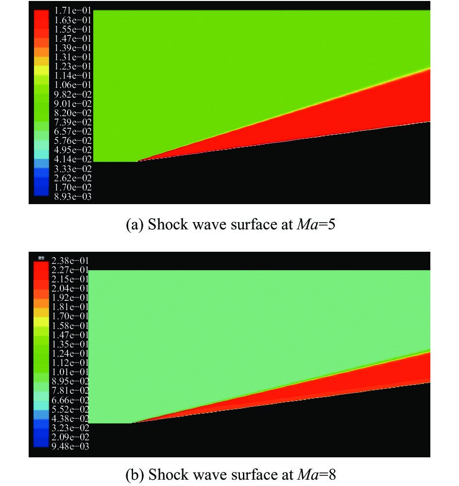
The deviations of the theoretically calculated shock wave angles from the actual values will cause the deflection angles to vary. Therefore, CFD simulations at Mach numbers of 5–8 were performed using the defined parameter values. The results demonstrated that stable shock wave structures formed over the wedge under all the aforementioned conditions (Fig. 4). However, the measured shock wave angles obtained through CFD simulations differed from the theoretically calculated ones.

Figure 4. CFD results of wedge shock waves at different Mach numbers
The measured shock wave angles were extracted from the CFD raster data. Table 3 presents the deviations of the simulated shock wave angles from the theoretical values at different Mach numbers.
Table 3. Measurement errors of shock wave angles at different Mach numbers (Unit: ("))
5.0 5.5 6.0 6.5 7.0 7.5 8.0 $\Delta \beta $ 0.0357 0.0806 0.0328 0.0431 0.0048 0.0606 0.0193 Under the same conditions, the measurement error,
$\Delta \;\beta $ , does not increase as the Mach number increases. Hence, further investigations are required to determine whether the simulation errors are random. -
According to the conclusion given in Section 4, when the measurement errors,
$\Delta \;\beta $ , and the angle of incidence,${\eta _1}$ , are smaller than${10^{ - 1}}$ ,$\Delta \;\beta $ has a negative and linear relation with the deflection angle.However, this is based on the assumption that
$Q' \approx Q$ ;$Q'$ and$Q$ were solved separately at different$\Delta \;\beta $ values from 0° to 5.0° at$Ma = 3,5,8$ . The similarity between$Q'$ and$Q$ was determined using$\left| {(Q' - Q)/Q} \right|$ , and the results are presented in Table 4.Table 4. Process parameters
$\left| {(Q' - Q)/Q} \right|$ at different Mach numbers (${10^{ - 4}}$ )Ma 5.0 6.0 7.0 8.0 0° 0.000 0.0000 0.0000 0.0000 0.5° 0.1890 0.2231 0.2528 0.2777 1° 0.3759 0.4427 0.5002 0.5479 1.5° 0.5606 0.6585 0.7420 0.8103 2.0° 0.7428 0.8703 0.9779 1.0648 2.5° 0.9225 1.0781 1.2080 1.3114 3.0° 1.0995 1.2816 1.4320 1.5500 3.5° 1.2737 1.4808 1.6499 1.7808 4.0° 1.4450 1.6756 1.8618 2.0038 4.5° 1.6134 1.8660 2.0676 2.2191 5.0° 1.7788 2.0519 2.2673 2.4269 From the table, it can be seen that the values of
$\left| {(Q' - Q)/Q} \right|$ are in the order of${10^{ - 4}}$ under all conditions. Therefore, the assumption that$Q' \approx Q$ stated in Section 3 is valid. -
The shock wave structure and the light deflection caused by it could be calculated by analytical methods as Section 2. If the CFD solutions were used as the actual results, the error analysis of the theoretical results could be carried out to improve the accuracy of the theoretical analytical model.
In the range of
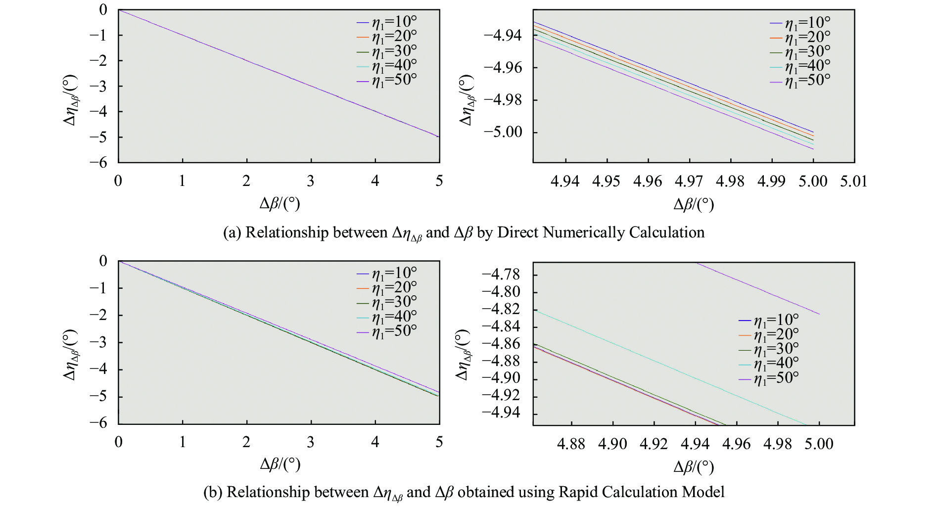
$\Delta \;\beta $ considered in this study, the error propagation,$\Delta {\eta _{\Delta \;\beta }}$ , can be calculated in different ways. Direct Numerically Calculation can be performed using Eq. (6), and Rapid Calculation Model from Eq. (19) can be used for rapid approximation results.From the figures below, it can be seen that
$\Delta {\eta _{\Delta \;\beta }}$ and$\Delta \;\beta $ generally have a negative linear relationship. When the angle of incidence is smaller than$50^\circ $ , the errors estimated via rapid approximation and direct numerical calculation are similar. However, as the angle of incidence,${\eta _1}$ , increases,${c_1} = \left(\dfrac{Q}{2} - \dfrac{{{Q^3}}}{2}\right)\eta _1^2 + \dfrac{{5{Q^3}}}{{18}}\eta _1^4 - Q$ in Eq. (17) could no longer be approximated to$ - Q$ . Therefore, the results obtained using Rapid Calculation Model started to deviate from those obtained through the Direct Numerically Calculation.If an equation similar to
$\Delta {\eta _{\Delta \;\beta }} \approx c + {c_1}\Delta \;\beta + {c_2}{(\Delta \;\beta )^2}$ in Eq. (17) is used to fit the relationship between$\Delta {\eta _{\Delta \;\beta }}$ and$\Delta \;\beta $ at a certain angle of incidence${\eta _1}$ , as shown in Fig.5(a), then the above expression becomes$\Delta \eta = a + {a_1}\Delta \;\beta + {a_2}{(\Delta \;\beta )^2}$ . Figure 6 shows the differences between the curve parameters used for the Direct Numerically Calculation solutions ($a,{a_1},{a_2}$ ) and those used Rapid Calculation Model ($c,{c_1},{c_2}$ ) for different${\eta _1}$ .
Figure 5. Linear relationships between deflection angles and shock wave

Figure 6. Comparison of parameters used in numerical calculation and simplified model
The results indicate that when the angle of incidence is within
$50^\circ $ , there are small differences between${a_1}$ and${c_1}$ , which are the parameters that critically influence$\Delta \;\beta $ . The relationship between$\Delta \;\beta $ and$\Delta \eta $ can be expressed effectively using Rapid Calculation Model from Eq. (19). In contrast, when the angle of incidence exceeds$50^\circ $ , the two parameters differ remarkably, and the approximation of Eq. (19) is no longer suitable. -
In this study, an analytical solution for wedge-shaped shock wave angles under hypersonic conditions was derived. Beam deflections due to shock waves were simulated at different Mach numbers and angles of incidence. The shock wave measurement error propagation was analyzed. Finally, the relationship between beam deflection and shock wave measurement errors was determined.
The following conclusions can be drawn from this study:
(1) Under hypersonic conditions, shock waves always generate over wedges with relatively stable structures. The wedge-shaped shock wave angle decreases and the density compression ratio increases as the Mach number increases.
(2) Shock wave surfaces significantly deflect light by approximately more than 1 arcseconds, up to 6.8", which is not a negligible error.
(3) A quantitative correction model of beam deflection due to shock waves over hypersonic vehicles was constructed as Eq. (20). This model can calculate error propagation rapidly, and it was proved to be effective when the light incident angle is less than 50°.
(4) Shock wave measurement errors are negatively and linearly correlated with the deflection angles, when the angle of incidence is within 50°. That means if the analytical algorithm of shock wave were used to correct the beam deflection, the error would be hold at the order of Shockwave Measurement Error,
$\Delta \;\beta $ , which is less than 0.1 arcseconds. It is important to model the shock wave locations and angles accurately from the establishment of adaptive correction models for shock wave fields.Further studies are required for examining the formation locations of shock waves and for approximating the superimposition of shock wave surfaces and density structures behind the shock wave surfaces.
Beam deflection correction model of wedge-shaped shock waves over hypersonic vehicles
-
摘要: 天文定姿是飞行器实现高精度自主导航的重要技术手段之一。高超声速飞行器在飞行过程中会产生激波,造成光线偏折,影响星敏感器的观测和天文定姿导航的性能。现代高超声速飞行器多采用乘波体设计,其载荷舱部分可简化为楔面结构。论文聚焦高超声速飞行器上楔面激波,基于空气动力学理论,给出了高超声速楔面激波结构参数的解析计算方法,以及激波对光线偏折影响的量化测算模型。提出了一种利用解析计算结果控制光线偏折的校正模型,讨论了激波角测量误差在该模型中的传播,证明了激波角测量误差与其引起的校正效果偏差其呈负线性相关。仿真试验表明,在高度20 km、马赫数5-8的条件下,楔面上方形成稳定的激波结构,对入射光线造成的偏折可达6.8";解析计算方法获得的激波角参数与试验结果误差在0.1"以内。这意味着运用该模型来校正光线偏折的误差可以控制在激波角观测误差的量级,可以显著提升观测精度。Abstract: Celestial attitude determination is one of the important technical means for high precision autonomous navigation of aircraft. Shock waves are generated along the surfaces of hypersonic vehicles, which cause beam deflection, affect the observation of star trackers and celestial navigation performances of these vehicles. Most modern hypersonic vehicles adopt the wave-rider design, and the payload bay can be simplified into a wedge plane structure. The shock waves over hypersonic vehicles with wedge-shaped upper surfaces were analyzed. Based on aero-optical theories an analytical calculation method of the structure parameters of the wedge shock wave and a quantitative calculation model of the impact of the shock wave on the deflection of light were given. A correction model was proposed to control the deflection of beam by using the analytical calculation results. The propagation of shock angle measurement error in this model was discussed, and it was proved that the shock angle measurement error was negatively linear correlated with the correction effect deviation caused by it. The simulation results show that under the condition of altitude 20 km and Mach number 5-8, a stable shock wave structure is formed above the wedge surface, and the deflection of incident beam can be up to 6.8 arcseconds. The error between the shock angle parameters obtained by the analytical calculation method and the test results is within 0.1 arcseconds. This means that the error of beam deflection correction by using this model can be controlled at the order of the shock angle measurement error, and the observation accuracy can be significantly improved.
-
Figure 3. Deflection angles due to shock wave surfaces at different Mach numbers and angles of incidence
Table 1. Shock angles and density ratios at different Mach numbers
Ma $\;\beta$ /rad${\rho _2}/{\rho _1}$ 5.0 0.3039 1.8491 5.5 0.2861 1.9436 6.0 0.2716 2.0393 6.5 0.2596 2.1359 7.0 0.2495 2.2330 7.5 0.2410 2.3301 8.0 0.2336 2.4270  下载: 导出CSV
Table 2. Deflection angles due to the shock wave surfaces at different Mach numbers and angles of incidence (Unit: ("))
Ma 10° 20° 30° 40° 50° 5.0 0.6040 1.2468 1.9778 2.8745 4.0825 5.5 0.6713 1.3856 2.1979 3.1943 4.5368 6.0 0.7394 1.5262 2.4209 3.5184 4.9971 6.5 0.8081 1.6680 2.6459 3.8454 5.4615 7.0 0.8771 1.8105 2.8720 4.1740 5.9282 7.5 0.9462 1.9532 3.0982 4.5028 6.3952 8.0 1.0152 2.0955 3.3239 4.8308 6.8611
下载: 导出CSV
Table 3. Measurement errors of shock wave angles at different Mach numbers (Unit: ("))
5.0 5.5 6.0 6.5 7.0 7.5 8.0 $\Delta \beta $ 0.0357 0.0806 0.0328 0.0431 0.0048 0.0606 0.0193
下载: 导出CSV
Table 4. Process parameters
$\left| {(Q' - Q)/Q} \right|$ at different Mach numbers (${10^{ - 4}}$ )Ma 5.0 6.0 7.0 8.0 0° 0.000 0.0000 0.0000 0.0000 0.5° 0.1890 0.2231 0.2528 0.2777 1° 0.3759 0.4427 0.5002 0.5479 1.5° 0.5606 0.6585 0.7420 0.8103 2.0° 0.7428 0.8703 0.9779 1.0648 2.5° 0.9225 1.0781 1.2080 1.3114 3.0° 1.0995 1.2816 1.4320 1.5500 3.5° 1.2737 1.4808 1.6499 1.7808 4.0° 1.4450 1.6756 1.8618 2.0038 4.5° 1.6134 1.8660 2.0676 2.2191 5.0° 1.7788 2.0519 2.2673 2.4269
下载: 导出CSV
-
[1] Wang Jianhua, Liu Luhua, Wang Peng. Integrated guidance and control scheme for hypersonic vehicles in dive phase [J]. Acta Aeronautica ET Astronautica Sinica, 2017, 38(3): 207-219. (in Chinese) doi: 10.7527/S1000-6893.2016.0223 [2] Chen Bing, Zheng Yong, Chen Zhanglei, et al. A review of celestial navigation system on near space hypersonic vehicle [J]. Acta Aeronautica ET Astronautica Sinica, 2020, 41(8): 32-43. (in Chinese) [3] Zhang Can, Lin Xubin, Hu Dongdong, et al. A review of technology development on foreign hypersonic vehicles [J]. Aerodynamic Missile Journal, 2019(2): 1-5, 15. (in Chinese) [4] Sayler K M. Hypersonic Weapons: Background and Issues for Congress[R]. Washington D C: Congressional Research Service, 2019. [5] Howard A E. Fast and furiously accurate[C]//Emerging & Disruptive Technologies Essay Contest, 2019. [6] Ouzt P J, Soloway D I, Moerder D D, et al. The role of guidance, navigation, and control in hypersonic vehicle multidisciplinary design and optimization[C]//16th AIAA/DLR/DGLR International Space Planes & Hypersonic Systems & Technologies Conference, 2009. [7] Zhang Wei, Zhang Heng. Research on problems of celestial navigation in space engineering [J]. Journal of Deep Space Exploration, 2016(3): 204-213. (in Chinese) doi: 10.15982/j.issn.2095-7777.2016.03.002 [8] Quan Wei, Liu Baiqi, Gong Xiaolin, et al. INS/CNS/GNSS Integrated Navigation Technology[M]. Beijing: National Defense Industry Press, 2011. (in Chinese) [9] Han Zhiping, Yin Xingliang. A method to calculate modulation transfer function for aerodynamic optical effect [J]. Modern Defence Technology, 2000, 28(6): 30-35. (in Chinese) doi: 10.3969/j.issn.1009-086X.2000.06.006 [10] Wu Lin, Fang Jiancheng, Yang Zhaohua. Study on aero-optical distortion simulation of high refraction index gradient regions in hypersonic turbulent flow [J]. Acta Optica Sinica, 2009, 29(11): 2952-2957. (in Chinese) doi: 10.3788/AOS20092911.2952 [11] Kong Xue, Ning Guodong, Yang Ming, et al. Study on aero optical effect of star navigation imaging [J]. Infrared and Laser Engineering, 2018, 47(10): 1031001. (in Chinese) doi: 10.3788/IRLA201847.1031001 [12] Li Yihan, Hu Haiyang, Wang Qiang. Radiative transmission property of infrared window in hypersonic vehicle [J]. Infrared and Laser Engineering, 2020, 49(4): 0404002. (in Chinese) doi: 10.3788/IRLA202049.0404002 [13] Kourta K, Sauvage R. Computation of supersonic mixing layers [J]. Physics of Fluids, 2002, 14(11): 3790-3797. doi: 10.1063/1.1505035 [14] Wang Jiangfeng, Wang Xudong, Li Jiawei, et al. Overview on aerodynamic design of cruising waverider configuration for hypersonic vehicles [J]. Acta Aerodynamica Sinica, 2018, 36(5): 705-728. (in Chinese) doi: 10.7638/kqdlxxb-2017.0117 [15] John B, Kulkarni V. Effect of leading edge bluntness on the interaction of ramp induced shock wave with laminar boundary layer at hypersonic speed [J]. Computers & Fluids, 2014, 96: 177-190. doi: 10.1016/j.compfluid.2014.03.004 [16] Chen Yong, Guo Longde, Zhang Long, et al. Investigation on aero-optical effects of high-speed turbulence over a slope with a cavity [J]. Acta Aerodynamica Sinica, 2010, 28(6): 666-671. doi: 10.3969/j.issn.0258-1825.2010.06.009 [17] Hammitt A G, Bogdonoff S M. Hypersonic studies of the leading-edge effect on the flow over a flat plate [J]. Journal of Jet Propulsion, 1956, 26(4): 241-246. doi: 10.2514/8.6969 [18] Chen Shuxing. Mathematical Analysis of Shock Wave Reflection[M]. Shanghai: Shanghai Scientific & Technical Publishers, 2018: 1-9. (in Chinese) [19] Kendall J M. An experimental investigation of leading-edge shock-wave-boundary-layer interaction at Mach 5.8 [J]. Journal of the Aeronautical Sciences, 1957, 24(1): 47-56. doi: 10.2514/8.3763 [20] Garvine R W. Shock wave transport effects on hypersonic leading edge flow [J]. AIAA Journal, 1966, 4(10): 1856-1858. doi: 10.2514/3.3798 [21] Butler T D. Numerical solutions of hypersonic sharp-leading-edge flows [J]. Physics of Fluids, 1967, 10(6): 1205. doi: 10.1063/1.1762264 [22] Yin Xingliang. Principle of Aero-Optics[M]. Beijing: China Aerospace Publishing House, 2003: 169-173. (in Chinese) [23] Maslov A A, Mironov S G, Poplavskaya T V, et al. Stability of hypersonic shock layer on plane plate [J]. Fluid Dynamics, 2004, 39(2): 181-188. doi: 10.1023/B:FLUI.0000030302.15633.26 [24] Li Kun, Li Ping, Chen Huimin. Study of refraction and reflection effect caused by shock wave on laser short-range detection [J]. Acta Armamentarii, 2008, 29(1): 28-32. (in Chinese) doi: 10.3321/j.issn:1000-1093.2008.01.007 [25] Liepmann H W, Roshko A. Elements of Gasdynamics[M]. New York: Dover Publications, 1956: 86-87. [26] Lu Zhongrong. A new analytical method determining the plane oblique shock angle [J]. Journal of Beijing Institute of Aeronautics and Astronautics, 1988(2): 87-92. (in Chinese) [27] Zhao Yan, Wang Tao, Xu Dong, et al. CFD grids-based transmission model of the rays propagating through the hypersonic flow field [J]. Acta Armamentarii, 2008, 29(3): 282-286. (in Chinese) doi: 10.3321/j.issn:1000-1093.2008.03.006 [28] Williams T, Bolender M A, Doman D B. An aerothermal flexible mode analysis of a hypersonic vehicle[C]//Aiaa Atmospheric Flight Mechanics Conference & Exhibit, Keystone, 2006. [29] Truesdale N, Skeen M, Diller J, et al. DayStar: Modeling the daytime performance of a star tracker for high altitude balloons[C]//Aiaa Aerospace Sciences Meeting Including the New Horizons Forum & Aerospace Exposition, 2013. [30] Wang Kan, Wang Meng. On the accuracy of Malley probe measurements of aero-optical effects: a numerical investigation [J]. Optical Engineering, 2013, 52(7): 071407. doi: 10.1117/1.OE.52.7.071407 -

 点击查看大图
计量
- 文章访问数: 215
- HTML全文浏览量: 68
- PDF下载量: 25
- 被引次数: 0


