


 下载:
下载:


-
人体运动姿势的长期监测对于神经退行性疾病(例如帕金森病、脑卒中等)的诊断与治疗具有重要的意义[1]。对膝关节的弯曲检测已被认为是与姿态相关的运动监测中的核心环节之一,因为帕金森病、脑卒中等患者在步行运动中有异常的膝关节屈曲和伸展模式[2]。因此,在基础研究和临床研究中膝关节弯曲度已被认定为生物力学分析中的测量结果指标[3]。通过获取运动过程中膝关节的弯曲信息,医师可以评估患者的病情或者康复效果,患者从而可以获得个性化的医疗服务。此外,现有的许多医学设备都是通过持续监测膝关节运动状态来获取诊断和康复信息[4]。
通常,膝关节运动信息捕捉系统可以通过基于图像传感器[5]和基于运动传感器[6]的方式搭建检测平台来实现。基于图像的运动捕捉系统容易受到背景和光照等环境因素的影响[7],对应用场景有较高的要求。基于运动传感器的捕获系统成本较低,可以与穿戴设备相结合,监测方式灵活,优化了后续的识别算法模型[8]。例如,电子应变计常被应用于获取关节弯曲信息,然而该方案容易受到温度和电磁场的干扰,影响了测试结果的可靠性。光学测角仪也被用于获取关节运动信息,例如动态测角仪[9]和光电编码器[10](Photoelectric encoder, PE)。然而,基于此类传感器的检测设备需要高精度机械结构的支持,在运行过程中会产生干扰噪声。此外,惯性测量单元已被用于检测膝关节弯曲信息,该传感器在使用过程中需要频繁的校准,对电磁场有较高的敏感度[11]。目前,已有研究报道表明传感器在应用过程中频繁的初始化校准会引起电磁干扰,从而影响设备的检测性能,不利于实际的工程应用。
近年来,光纤传感器以其体积小、生物相容性好、抗电磁干扰能力强等优点在生物医学传感领域受到了越来越多的重视。研究人员利用塑料光纤(Plastic optical fiber, POF)作为曲率传感器对人体关节运动信息进行监测[12]。由于塑料光纤不足的灵敏度,使得在应用前需要将其加工成不对称结构来提高其灵敏性。例如将光纤侧边抛光[13],增加光纤凹陷的深度[14],在光纤表面蚀刻齿形[15]。然而,该类方法增加了传感器内光信号的损耗,并且难以确保结构的一致性,还需进行更深入的研究。
此外,已有研究人员将改进的光纤光栅传感器(Fiber Bragg grating, FBG)应用于膝关节运动弯曲的测量[16]。与基于强度解调的POF传感器相比,基于频谱解调的FBG具有更高的灵敏度[17]。然而,FBG传感器在监测过程中传输的光信号强度易衰减,存在应力和温度交叉敏感等问题。此外,复杂的生产工艺和昂贵的加工设备使该类传感器增加了实际商业应用的成本。近年来,基于马赫曾德尔干涉(Mach-Zehnder interferometer, MZI)的光纤传感器被报道用于弯曲度的检测,该类传感器通常采用非对称结构,例如采用锥形结构的单模光纤、错位熔接单模光纤和多模光纤等。该类弯曲传感器与基于FBG的传感器相比结构简洁、封装灵活、灵敏度高、研制成本低,更适用于关节弯曲变化的持续测量。
文中提出一种基于光纤马赫曾德尔干涉曲率传感器(Mach-Zehnder interferometer-based directional bending, MZI-BDB)的膝关节定向弯曲检测方法。研制了基于MZI的曲率传感器,该传感器通过将偏心光纤(Eccentric core fiber, ECF)与单模光纤(Single mode fiber, SMF)错位熔接而成,封装于软硅树脂片内,通过绑带固定于膝关节处,能够持续获取膝关节弯曲信息。扫频激光光源以及基于频谱的解调技术被应用于该检测系统中。为了验证传感器的可靠性,PE(Omron Inc., 日本)传感器同时对膝关节弯曲信息进行采集。与已报道的基于强度解调的POF传感器相比,文中提出的MZI-BDB传感器具有更高的灵敏度。此外,与FBG传感器相比,MZI-BDB传感器制作简单,不受温度交叉影响。这些特点使得基于该传感器的检测系统在步态信息获取和分析中具有潜在的应用价值。
-
膝关节弯曲检测系统示意图如图1所示,该系统中同时采用MZI-BDB传感器和PE传感器对膝关节弯曲信息进行提取,并将实验数据进行对比分析。光源采用自制扫频光源,主要由型号为IPSAD1304半导体激光放大器(InPhenix Inc., 美国),法布里-珀罗滤波器(Micron OpticsInc., 美国),偏振控制器,光纤耦合器和隔离器等构成。扫频光源的扫描范围为1 285~1 348 nm,瞬时线宽为0.02 nm,扫频速率2.5 kHz时输出功率为8.4 mW。

图 1 膝关节弯曲检测系统示意图
Figure 1. Schematic diagram of knee bend detection system
扫频光源的输出光信号通过SMF连接到光纤耦合器1上,光纤耦合器1的输出端分别连接至光纤隔离器1和2。光纤耦合器2和3将耦合的扫频光信号传输至MZI-BDB传感器,传感器的透射光信号通过光电探测器1和2转换成电信号,将在信号处理系统中进行解调分析。
-
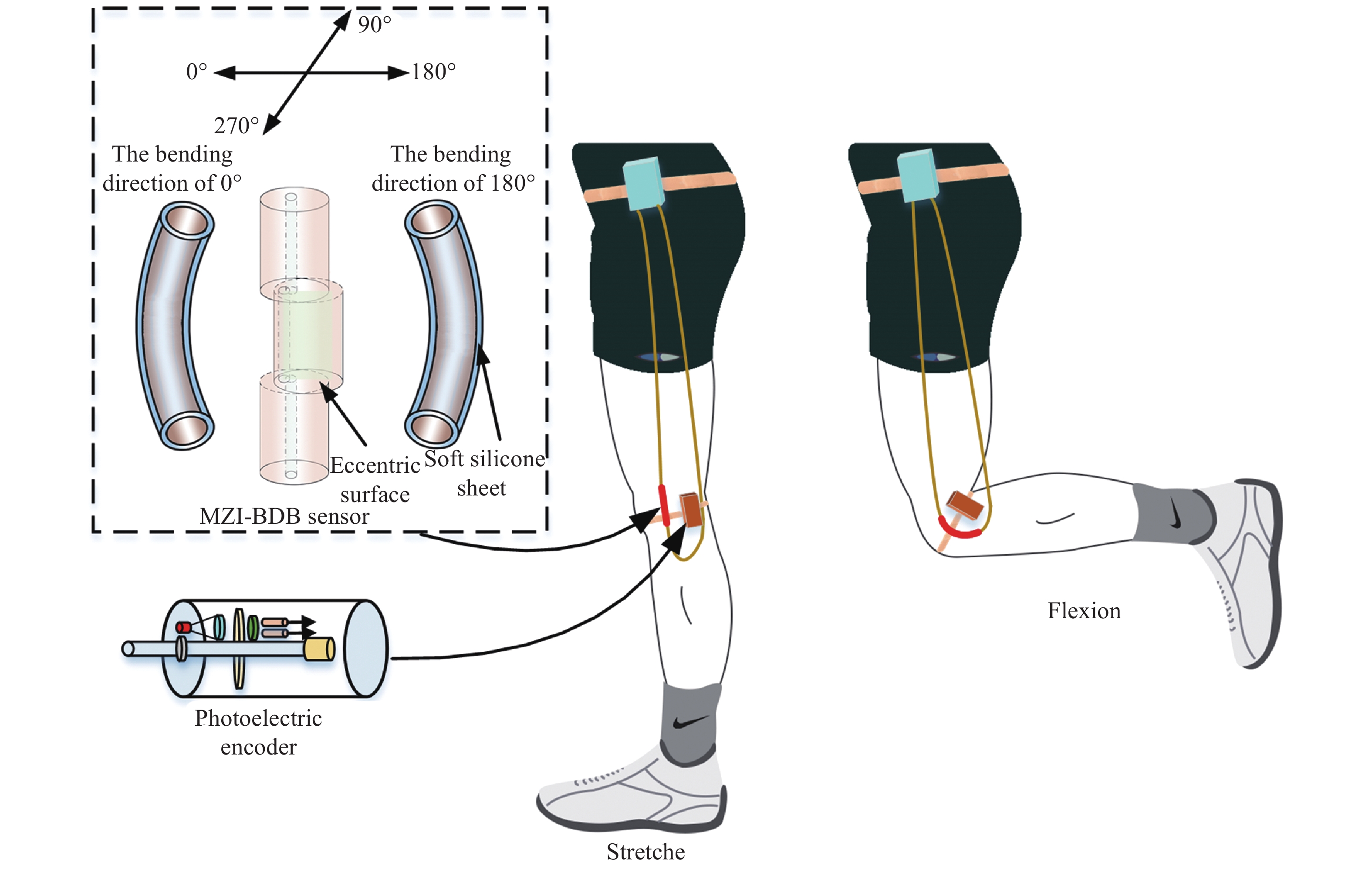
MZI-BDB传感器封装于软硅树脂片中,通过绑带固定在膝关节处,实物图如图2所示。MZI-BDB传感器内偏芯面平行于肌肉表面,膝关节在伸展和弯曲状态下的检测示意图如图3所示。

图 2 (a) 传感器封装示意图; (b) 传感器封装、固定膝关节示意图
Figure 2. (a) Schematic diagram of sensor package; (b) Schematic diagram of sensor is encapsulated and fixed on the knee joint
PE传感器作为验证平台固定于MZI-BDB传感器附近。关节在测试过程中进行屈曲和伸展时,MZI-BDB传感器被诱导发生弯曲。当膝关节由伸展状态变成屈曲状态时,膝关节角度减小,MZI-BDB传感器被诱导发生0°方向弯曲(正向弯曲);当膝关节由屈曲状态变成伸展状态时,膝关节角度增加,MZI-BDB传感器被诱导发生180°方向弯曲(负向弯曲)。由于MZI-BDB传感器内SMF与ECF之间的位错熔接,导致了基模和包层模之间的干涉模场发生变化,透射的谐振波长发生漂移。通过对谐振波长漂移值的监测,可以获取关节弯曲信息。

图 3 膝关节弯曲检测示意图
Figure 3. Schematic diagram of the knee joint bending detection
-
MZI-BDB传感器包括两个部分:SMF和ECF。传感器的结构示意图、ECF在电子显微镜下的横切面图以及偏心的分布示意图如图4所示。ECF的纤芯的偏心距离(d1)是30.02 µm;纤芯和包层的折射率分别是1.468和1.457。ECF的两端通过型号80S的光纤熔接机(Fujikura Inc., 日本)与SMF错位融合而成。

图 4 (a) MZI-BDB传感器设计示意图; (b) 偏心光纤在电子显微镜下的横切面图
Figure 4. (a) Schematic diagram of the MZI-BDB sensor design; (b) Microscope image of the cross-sections of the eccentric core fiber
熔接前准备工作如下:将光纤熔接机设置成“Manual”手动模式,光纤熔接类型选择“SS”,持续放电电流设置成“−23 bit”,持续放电时间选择350 ms。首先将需要熔接的单模光纤通过FC/PC接口连接至扫频光源,由于光功率计采用端面接收,因此将ECF一端利用FC/PC接口直接和光功率计相连,保证在进行熔接过程中的实时监测;利用光纤熔接机手动模式调节ECF与第一段SMF在X轴、Y轴相对位置,当光功率计监测光功率值最大时表示SMF与ECF纤芯完全对准,此后继续采用小步进模式进行调节两芯相对位置,当光功率计显示数值衰减至约50%时,代表SMF与ECF纤芯错位约4 μm,此时进行熔接,并且完毕后将ECF切割3 cm。将切割后的ECF另一端与另一段SMF在光纤熔接机中进行错芯熔接,SMF的另一段连接至光谱仪,通过观察光谱仪中干涉条纹对比度变化的方式进行调节。通过光纤熔接机的调节,光谱仪上的干涉条纹对比度会出现由最小到最大,再到最小,再逐渐变大这种周期性变化。这是由于光纤熔接机在初始状态下将ECF和SMF中心纤芯完全对准,此时干涉对比度最小。当调节相对位置时,SMF纤芯进入ECF偏心纤芯区域,SMF纤芯与ECF偏心纤芯产生错位,干涉对比度增强,当错位约4 μm时干涉对比度最大;当继续调节两芯相对位置时,SMF纤芯与ECF的偏心纤芯错位距离减少,干涉对比度减弱;继续调节时,两芯的错位距离再次增加,干涉对比强度开始增强;当SMF纤芯逐渐远离ECF偏心纤芯,错位距离减少,干涉对比度随之变小。根据以上变化规律,将SMF纤芯与ECF的纤芯在干涉对比度最强时进行错位熔接。
-
MZI-BDB传感器工作原理如下:传感器被封装于软硅树脂片内,通过绑带固定于膝关节处,随着受试者关节的运动,传感器被诱导弯曲。当扫频激光光源的光信号从MZI-BDB传感器中SMF和ECF的第一个熔接点透射时,ECF的包层模被激发。在第二个熔接点处,ECF的基模和包层模耦合进入第二个SMF的纤芯。如果基模和包层模的透射光信号存在相位差,则第二次耦合会产生干涉,并且在该结构中激发更多的高阶包层模。
在关节弯曲检测过程中,MZI-BDB传感器的弯曲模拟示意图如图5所示,S1是SMF和ECF的第1熔接面,S2是ECF与SMF的第2熔接面,S1和S2的夹角如公式(1)所示:
$$\theta \approx \frac{{{L_{{{cl}}}}}}{R} = \frac{{{L_{co}}}}{{R + d}}$$ (1) 式中:R为弯曲曲率半径;d为偏心纤芯和中性面的距离;Lcl和Lco分别为包层模和基模长度。公式(1)可以转换成:
$${L_{{{co}}}} = \left( {1 + d \cdot C} \right) \cdot {L_{cl}}$$ (2) 式中:C为膝关节弯曲曲率,代表膝关节在运动过程中的弯曲程度。弯曲曲率越大,表示膝关节的弯曲程度越大。光信号从ECF透射后,基模和包层模之间的相位差γ如公式(3)所示:
$$\gamma = \frac{{2\pi }}{\lambda }\left( {{n_{co}}{L_{co}} - {n_{cl,i}}{L_{cl}}} \right)$$ (3) 式中:nco和ncl,i分别为基模和第i阶包层模的有效折射率;λ为扫频激光光源波长。当相位差满足
$\gamma = \left( {2k + 1} \right) \cdot \pi $ ,谐振波长如公式(4)所示:$${\lambda _d} = \frac{{2({n_{co}}{L_{co}} - {n_{cl,i}}{L_{cl}})}}{{2k + 1}}$$ (4) 传感器被固定于膝关节处,其芯内中性面垂直于肌肉表面。当受试者正常行走时,膝关节的运动会诱导MZI-BDB传感器发生弯曲。此时基模的nco和Lco会发生明显的变化,然而包层模的ncl,i和Lcl改变量比基模的改变量要小。因此,基模与包层模之间的光程差(
${n_{co}}{L_{co}} - {n_{cl,i}}{L_c}_l$ )发生变化,导致干涉谐振波长发生漂移。具体来说,当膝关节运动,诱导传感器在0°方向发生弯曲(正向弯曲),基模与包层模之间的光程差(${n_{co}}{L_{co}} - {n_{cl,i}}{L_c}_l$ )增大,从而导致干涉谐振波长增加;当膝关节诱导传感器向180°方向弯曲(负向弯曲),基模与包层模之间的光程差(${n_{co}}{L_{co}} - {n_{cl,i}}{L_c}_l$ )减小,从而导致干涉谐振波长减小。
图 5 MZI-BDB传感器的弯曲模拟示意图
Figure 5. Schematic diagram of bending simulation of MZI-BDB sensor
-
检测MZI-BDB传感器特性的装置示意图如图6所示,该装置由扫频光源、偏振控制器、光纤旋转夹具、金属板、千分尺以及光谱仪(YOKOGAWA, 日本)构成。扫频光源输出光信号通过单模光纤传输至MZI-BDB传感器,其透射光信号输入光谱仪。其中,偏振控制器确保光信号在该过程中偏振态保持不变;光纤旋转夹具用于调整MZI-BDB传感器的弯曲方向;传感器被固定于金属板上,放置砝码(3 g)确保传感器在测试过程中始终紧贴于金属板;千分尺用于调节被测传感器的弯曲曲率。按照2.1节所述步骤熔接后,将固定于载玻片上的MZI-BDB传感器摆放状态进行标记,此时载玻片平面为90°方向和270°方向所在平面,垂直于载玻片平面为0°方向和180°方向所在平面,传感器的传感方位基于以上标记确定。

图 6 MZI-BDB传感器特性检测装置示意图
Figure 6. Schematic diagram of MZI-BDB sensor characteristic detection device
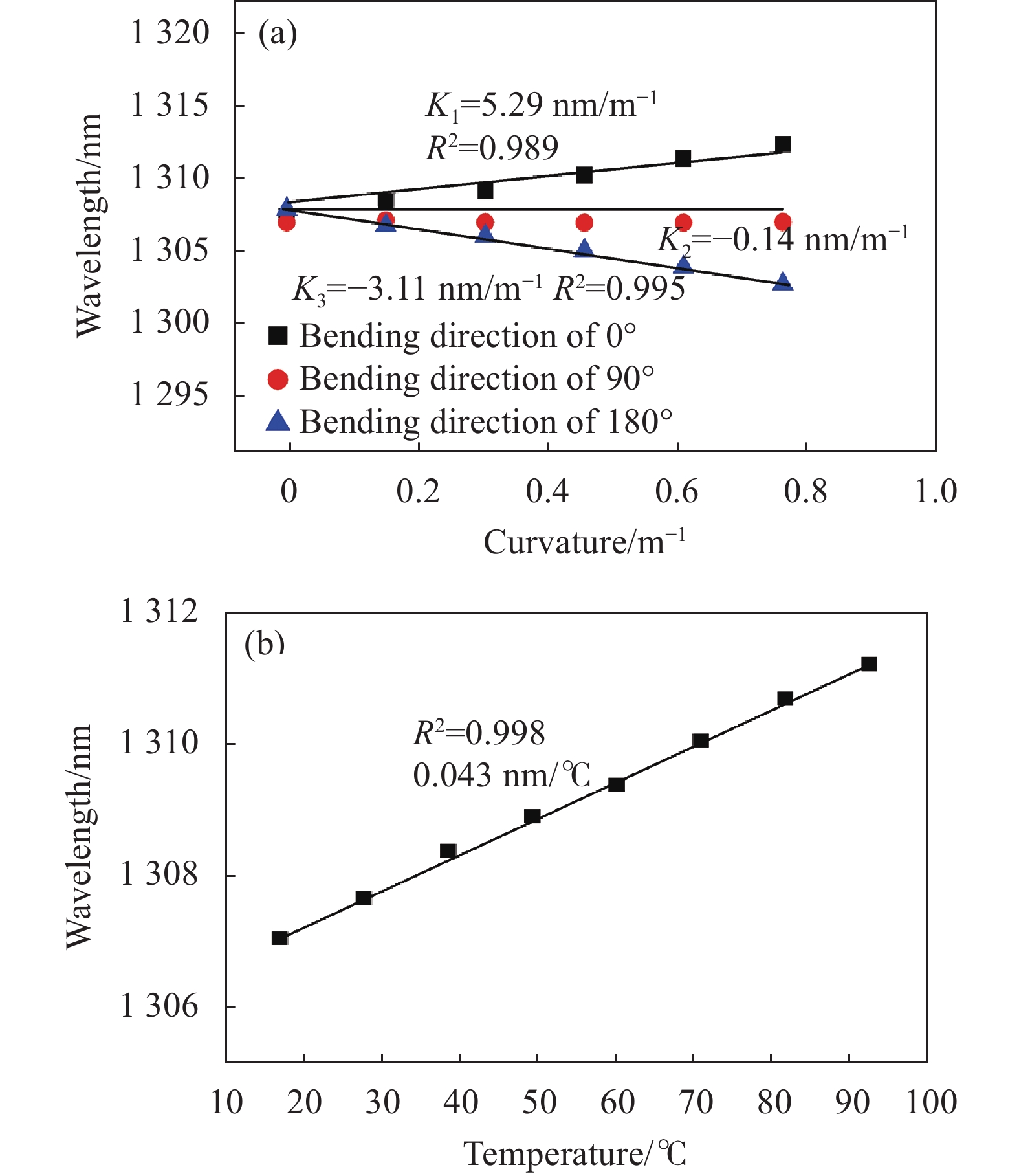
调节光纤旋转夹具,使得MZI-BDB传感器分别处于0°、90°和180°弯曲方向下。随着弯曲曲率的调节,通过光谱仪检测出传感器在不同弯曲方向和弯曲曲率下透射光的谐振波长变化情况。该传感器研制长度为35.1 mm,千分尺调节MZI-BDB传感器的曲率步长和范围分别是0.1 m−1、0~2 m−1。图7中,在0°弯曲方向下(正向弯曲),MZI-BDB传感器的弯曲灵敏度为5.29 nm/m−1,分辨率为0.11 m−1,线性拟合相关系数R2为0.989;在180°弯曲方向下(负向弯曲),MZI-BDB传感器的弯曲灵敏度为−3.11 nm/m−1,分辨率为0.12 m−1,线性拟合相关系数R2为0.995。理想情况下在90°弯曲方向下,MZI-BDB传感器的弯曲灵敏度应为0,然而实验测量结果是−0.14 nm/m−1,通过分析认为是测量过程中弯曲方向的误差所导致。将传感器水平放置在加温板上,温度调节范围为20~90 ℃,所测MZI-BDB传感器的温度灵敏度为0.043 nm/℃,相关系数R2为0.998,该结果表明传感器对温度不敏感,具备避免在检测过程中受温度交叉影响的特性。

图 7 (a) 不同曲率下,0°、90°和180°弯曲方向谐振波谷波长漂移变化; (b) 不同温度下传感器谐振波谷波长漂移变化
Figure 7. (a) Wavelength shifting variation of the resonance wave under different curvatures for bending directions of 0°, 90°, and 180°; (b) Wavelength shifting variation of the resonance wave under different temperatures
-
受试者为一名33岁的男性志愿者,实验分两个阶段进行。在实验的前期准备阶段需要正确固定传感器,并进行静态校准。MZI-BDB传感器封装于软硅树脂片中,通过绑带固定在膝关节处。安装MZI-BDB传感器时将其已经标记的偏心所在面平行于肌肉表面,即传感器检测的0°方向和180°方向平面平行于膝关节的伸展和屈曲运动平面。在受试者运动过程中,膝关节伸展和屈曲可以通过传感器所检测的0°方向或180°方向来确定。同时,膝关节运动过程中大腿与小腿的角度变化可以通过诱导传感器发生弯曲来检测。校准系数通过拟合一阶多项式的角度和参考数据来确定。
在第一阶段,受试者进行所需的屈伸运动,为了便于实验观察,整个屈伸运动被划分为四组动作:初始(Original),紧绷(Uptight),迈步(Begin to take a step),收步(After mounted)。检测左、右膝关节弯曲信息的MZI-BDB传感器在每组动作下被选择观察点的谐振波谷的波长漂移变化情况如图8所示。当受试者在自然站立初始状态下,被选择观察点的谐振波谷波长为1 308.024 nm(λ1-1);当受试者在紧绷状态下,谐振波谷的波长发生漂移至1 308.724 nm(λ1-2);当受试者迈步后,膝盖弯曲到最大程度,谐振波谷的波长发生漂移至1 315.188 nm(λ1-3);收步后,谐振波谷的波长发生漂移至1 308.284 nm(λ1-4)。类似的,右膝关节的周期性屈曲和伸展使得谐振波谷的波长变化规律与固定在左膝关节的MZI-BDB传感器一致。由于传感器固定在左右膝关节位置的误差,导致在屈伸运动过程中谐振波谷的波长变化值会有差异。
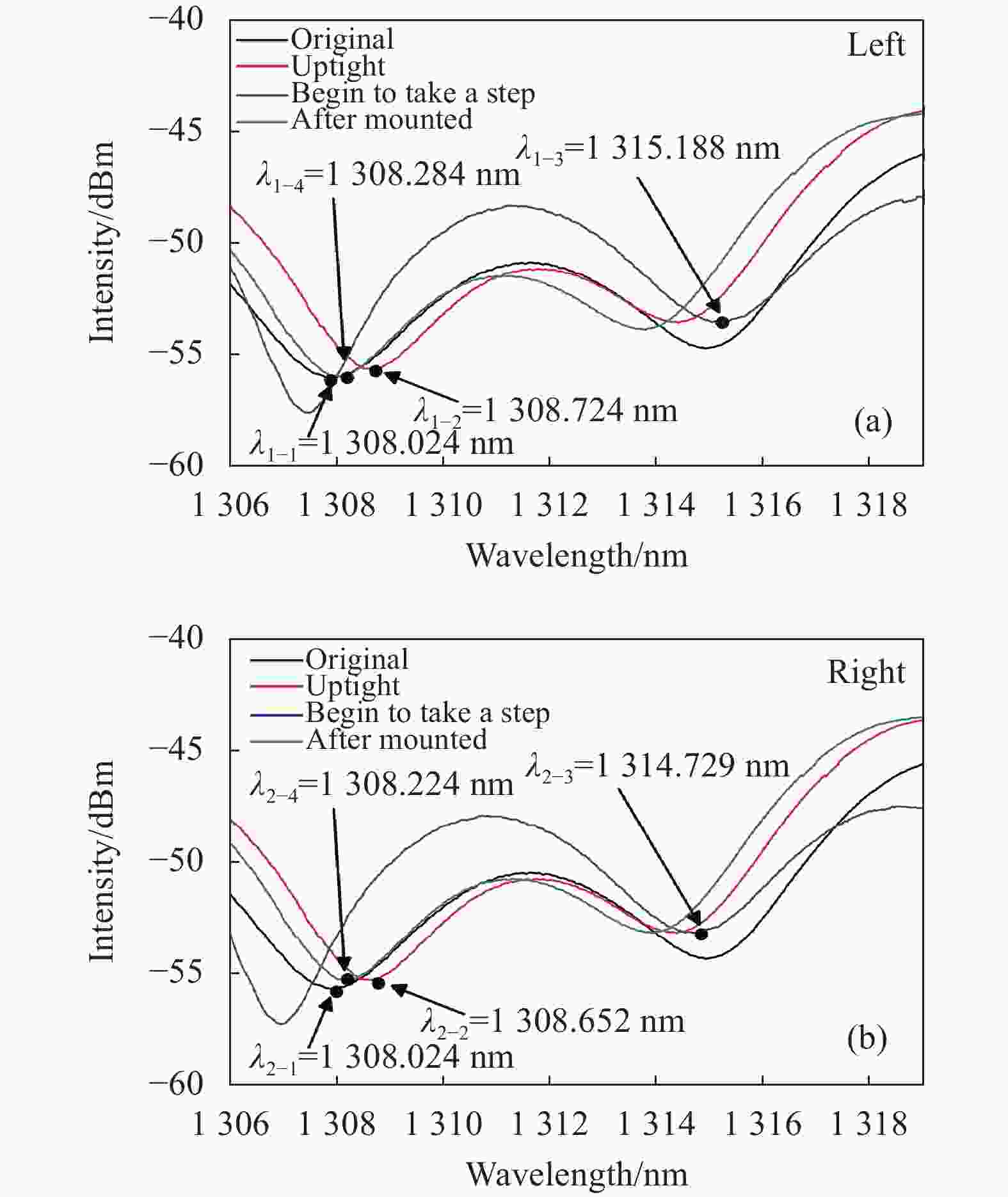
图 8 MZI-BDB传感器的谐振波谷波长漂移。 (a)左膝关节; (b) 右膝关节
Figure 8. Wavelength shift of the resonance wave of the MZI-BDB sensor. (a) Left knee joint bending; (b) Right knee joint bending
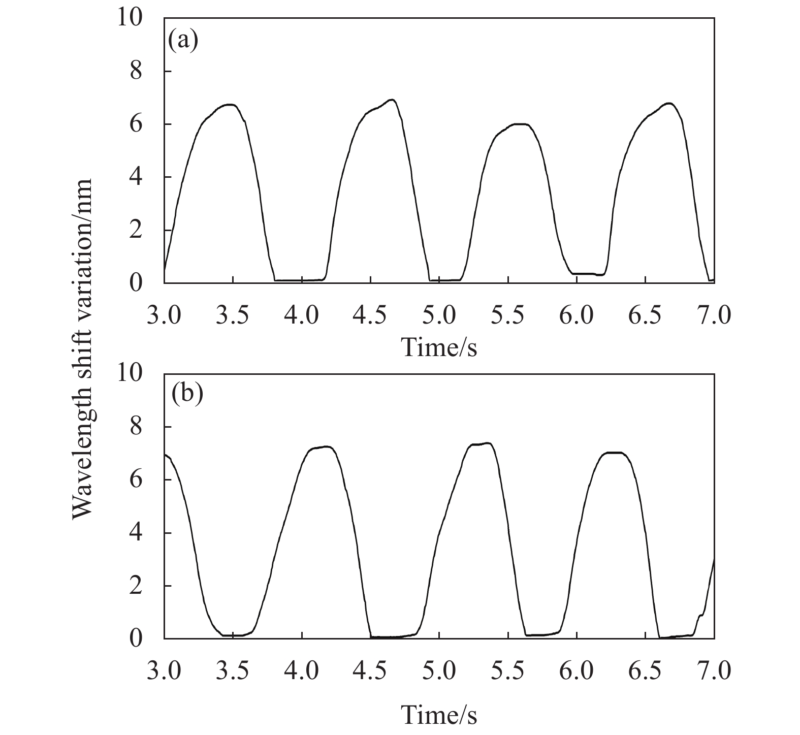
在第二阶段,受试者以正常速度行走,固定在膝关节上的MZI-BDB传感器连续记录膝关节定向弯曲数据,如图9所示。该图显示固定在左膝关节和右膝关节的MZI-BDB传感器所采集的数据在时域上图形互补。当MZI-BDB传感器的波长漂移值最大时,膝关节屈曲幅度最大,受试者处于“迈步”状态。当MZI-BDB传感器的波长漂移值最小时,膝关节处于“紧绷”状态。

图 9 MZI-BDB传感器在受试者行走时的谐振波谷波长漂移。(a) 右膝关节; (b) 左膝关节
Figure 9. Wavelength shift of the resonant Valley in the MZI-BDB sensor when the subjects are walking. (a) Right knee joint bending; (b) Left knee joint bending
从图9中可知,受试者右膝关节从“紧绷”状态到“迈步”状态的时间为0.6 s;左膝关节从“紧绷”状态到“迈步”状态的时间为0.65 s。右膝关节和左膝关节处于“迈步”状态时,传感器波长漂移值最大,分别为:6.374 nm和6.564 nm。此外,该图显示谐振波谷的波长从最小值变化到最大值的上升时间为1.2 s,从最大值变化到最小值的下降时间为1.1 s。
通过比较两个传感器谐振波谷的波长漂移最大值和最小值,可知受试者的右膝关节比左膝关节在运动时更放松。因为MZI-BDB传感器在“紧绷”状态下谐振波谷的波长偏移更小,说明膝盖更接近于初始状态。MZI-BDB传感器在“迈步”状态下的谐振波谷的漂移较大,说明左膝关节的摆动幅度较大。
-
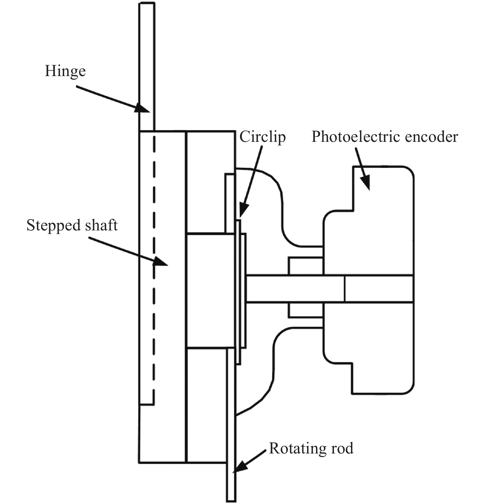
在第二阶段,当受试者以正常速度行走时,将PE传感器放置在MZI-BDB传感器附近,同时获取膝关节的屈曲和伸展数据。PE传感器的机械尺寸与结构盒相匹配,运动时大腿与小腿角度变化需被光电编码器准确采集。编码器安装结构图如图10所示,主要由光电编码器、卡圈、转动杆、阶梯轴、铰链构成。将光电编码器的光栅盘固定于连接在大腿侧的转动环,转动环固定在人体运动的大腿侧,图10中3转动杆与转动环相连。当受试者运动时光栅盘可以与大腿同速旋转。同时,光电编码器的光电转换装置固定于结构盒内侧。随着受试者在行走过程中关节的转动,带动编码器的相对转动,从而光电转换装置与光栅盘的相对角位移能够正确反应膝关节的运动状态。

图 10 光电编码器安装结构图
Figure 10. Installation structure diagram of photoelectric encoder
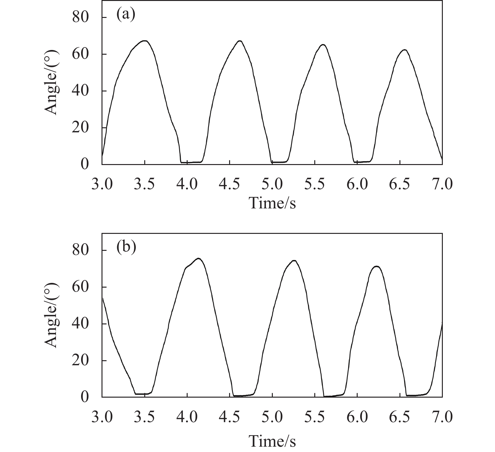
固定在左、右膝关节的PE传感器获取的数据如图11所示。由图可知,来自右膝关节和左膝关节的PE传感器数据显示在坐标轴上的波形互补。当屈曲角度达到最大时,膝关节的屈曲幅度最大处于“迈步”状态;当屈曲角度达到最小时,膝关节处于“紧绷”状态。受试者右膝关节从“紧绷”状态到“迈步”状态的时间为0.6 s;左膝关节从“紧绷”状态到“迈步”状态的时间为0.65 s。右膝关节和左膝关节处于“迈步”状态时,传感器监测角度值最大,分别为:73.69°和73.92°。此外,图中显示膝关节弯曲角度从最小值变化到最大值的上升时间为1.2 s,从最大值变化到最小值的下降时间为1.1 s。

图 11 行走时通过光电编码器获得的角度: (a) 右膝关节; (b) 左膝关节
Figure 11. Angle obtained through the optical-electricity encoders during walking: (a) Right knee joint; (b) Left knee joint
通过比较两个传感器获取膝关节角度的最大值和最小值,可知通过PE传感器的检测数据能够得出受试者的右膝关节比左膝关节更放松的识别结果。因为在“紧绷”状态下的膝关节角度更小,意味着膝盖更接近于初始状态。在“迈步”状态下左膝关节处的PE检测的角度更大,说明左膝关节相比右膝关节的摆动幅度更大。
-
通过将MZI-BDB传感器和PE传感器所获取的膝关节弯曲数据进行比较可知,两种传感器所获取的数据从最小值变换到最大值的上升时间都是1.2 s,从最大值变换到最小值的下降时间都是1.1 s,说明两种传感器所监测数据的上升区和下降区所需要的时间一致,证明MZI-BDB传感器与PE传感器在监测膝关节弯曲过程中具有一致的响应时间。同时,MZI-BDB传感器和PE传感器都监测到了在“紧绷”状态下膝盖更接近于初始状态,在“迈步”状态下左膝关节相比右膝关节的摆动幅度更大,证明MZI-BDB传感器监测到的膝关节弯曲过程中的运动特征与PE传感器所监测的运动特征保持一致。
该检测系统中光纤耦合器和光纤隔离器的使用增加了系统的光损耗。传感器被封装在软硅树脂片中,通过绑带固定于膝关节,在实验测试中发现随着膝关节弯曲运动,传感器在软硅树脂片中的位移会导致测量数据存在误差。在未来的工作中,笔者计划通过将传感器封装在一个紧凑的硅胶套管中来解决上述问题。此外,由于裸纤易折断,在制作传感器时需要小心操作。
-
文中提出了一种基于MZI-BDB传感器的膝关节定向弯曲检测系统。MZI-BDB传感器由ECF和SMF错位熔接而成,固定于膝关节处。当膝关节屈曲和伸展时,诱导MZI-BDB传感器发生弯曲,其干涉场的模场状态发生变化。因此,通过检测MZI-BDB传感器内模场状态变化过程中谐振波长的漂移值,能够对膝关节的弯曲状态进行监测。此外,该检测系统可以区分被测目标的正向弯曲(0°弯曲方向)和负向弯曲(在180°弯曲方向)。检测系统在正向弯曲和负向弯曲的测量范围是0°~90°;在正向弯曲的灵敏度和分辨率分别为5.29 nm/m−1和0.11 m−1;在负向弯曲处的灵敏度和分辨率分别为−3.11 nm/m−1和0.12 m−1。此外,MZI-BDB传感器的温度敏感度为0.043 nm/℃,证明该传感器对温度的不敏感特性。通过对比实验,验证了MZI-BDB传感器与PE传感器在获取膝关节弯曲信息时的响应度保持一致。该检测系统结构紧凑、制造成本低、抗电磁干扰能力强,在步态分析领域具有潜在的应用价值。
Research on knee joint curvature detection system based on fiber optic MZI-BDB curvature sensor
-
摘要: 在人体运动监测的过程中,膝关节运动信息在中老年慢性疾病的诊断和康复评估方面具有重要意义。研制了一种基于光纤马赫曾德尔干涉曲率传感器(Mach-Zehnder interferometer-based directional bending,MZI-BDB)的膝关节弯曲检测系统。该系统由MZI-BDB传感器、扫频激光光源、光纤耦合器、光纤隔离器、光电探测器及信号处理系统构成。MZI-BDB传感器由偏心光纤和单模光纤错位熔接而成,封装于软硅树脂片内,通过绑带固定于膝关节处。当膝关节屈曲和伸展时,诱导MZI-BDB传感器发生弯曲,传感器内透射光信号干涉场的模场状态发生变化,谐振波长发生漂移,从而对膝关节的弯曲方向和曲率进行监测。MZI-BDB传感器在正向和负向弯曲的测量角度范围为0°~90°;在正向弯曲方向上灵敏度和分辨率分别为5.29 nm/m−1和0.11 m−1;在负向弯曲方向上的灵敏度和分辨率分别为−3.11 nm/m−1和0.12 m−1。实验测试MZI-BDB传感器温度敏感度为0.043 nm/℃,该结果显示传感器对温度的不敏感特性。光电编码器与MZI-BDB传感器同时进行数据的传感采集。实验结果表明:该检测系统和光电编码器验证平台在准确度和响应度上具有一致性。Abstract: In the monitoring process of human motion and posture, knee movement information was of great significance in the diagnosis and rehabilitation evaluation of chronic diseases in the middle and old age. The knee directional bending measurement device using a Mach-Zehnder interferometer-based directional bending (MZI-BDB) sensor was presented in this paper. The system consisted of MZI-BDB sensor, swept laser light source, optical fiber coupler, optical fiber isolator, photodetector and signal processing system. MZI-BDB sensor was fabricated by fusion-splicing a section of eccentric core fiber (ECF) between two single-mode fibers (SMF) with core-offset. It was encapsulated in a soft silicone sheet and fixed to the knee joint by a band. When the knee joint was flexed and extended, the MZI-BDB sensor was led to bend, causing the modal interferes of the sensor changes and the resonant wavelength shifted, so as to monitor the bending direction and curvature of the knee joint. The range of measurement of MZI-BDB sensor was 0°-90° at the positive and negative bendings respectively. At the positive bending (bending direction of 0°), the proposed MZI-BDB sensor sensitivity and resolution were 5.29 nm/m−1 and 0.11 m−1 respectively. The sensitivity and resolution were −3.11 nm/m−1 and 0.12 m−1 at the negative bending (bending direction of 180°). The temperature sensitivity of the proposed MZI-BDB was 0.043 nm/℃, which had minimal effect on the experiments. Furthermore, the photoelectric encoder and MZI-BDB sensor were used for data acquisition simultaneously. The experimental results show that the detection system and the photoelectric encoder verification platform are consistent in accuracy and responsiveness.
-
Key words:
- optical fiber sensing /
- eccentric core optical fiber /
- curvature sensor /
- gait analysis
-
图 2 (a) 传感器封装示意图; (b) 传感器封装、固定膝关节示意图
Figure 2. (a) Schematic diagram of sensor package; (b) Schematic diagram of sensor is encapsulated and fixed on the knee joint
图 4 (a) MZI-BDB传感器设计示意图; (b) 偏心光纤在电子显微镜下的横切面图
Figure 4. (a) Schematic diagram of the MZI-BDB sensor design; (b) Microscope image of the cross-sections of the eccentric core fiber
图 5 MZI-BDB传感器的弯曲模拟示意图
Figure 5. Schematic diagram of bending simulation of MZI-BDB sensor
图 6 MZI-BDB传感器特性检测装置示意图
Figure 6. Schematic diagram of MZI-BDB sensor characteristic detection device
图 7 (a) 不同曲率下,0°、90°和180°弯曲方向谐振波谷波长漂移变化; (b) 不同温度下传感器谐振波谷波长漂移变化
Figure 7. (a) Wavelength shifting variation of the resonance wave under different curvatures for bending directions of 0°, 90°, and 180°; (b) Wavelength shifting variation of the resonance wave under different temperatures
图 8 MZI-BDB传感器的谐振波谷波长漂移。 (a)左膝关节; (b) 右膝关节
Figure 8. Wavelength shift of the resonance wave of the MZI-BDB sensor. (a) Left knee joint bending; (b) Right knee joint bending
图 9 MZI-BDB传感器在受试者行走时的谐振波谷波长漂移。(a) 右膝关节; (b) 左膝关节
Figure 9. Wavelength shift of the resonant Valley in the MZI-BDB sensor when the subjects are walking. (a) Right knee joint bending; (b) Left knee joint bending
-
[1] Nathalie C, Bairc W, Susan M, et al. Prediagnostic markers of idiopathic Parkinson’s disease: Gait, visuospatial ability and executive function [J]. Gait & Posture, 2019, 68: 500-505. [2] Rossom S, Smith C, Thelen D, et al. Knee joint loading in healthy adults during functional exercises: Implications for rehabilitation guidelines [J]. J Orthop Sport Phys, 2018, 48(3): 162-173. doi: 10.2519/jospt.2018.7459 [3] Mohamed A, Ren J, Sharaf A, et al. Optimal path planning for unmanned ground vehicles using potential field method and optimal control method [J]. International Journal of Vehicle Performance, 2018, 4(1): 1-14. doi: 10.1504/IJVP.2018.088780 [4] Song L M, Huang H Z, Chen Y, et al. Fast measurement of human body posture based on three-dimensional optical information [J]. Infrared and Laser Engineering, 2020, 49(6): 20200079. (in Chinese) doi: 10.3788/irla.7_2020-0079 [5] Ciechanowicz K, Stolarz M, Glabet G, et al. Biomechanical image of the knee motion in patients with chronic anterior instability of the knee joint before and after Kinesio Taping [J]. J Back Musculoskelet, 2019, 33(7): 1-9. [6] Bloomfield, Aaron R, Fennema, et al. Proposal and validation of a knee measurement system for patients with osteoarthritis [J]. IEEE T Bio-med Eng, 2019, 66(2): 319-326. doi: 10.1109/TBME.2018.2837620 [7] Zhu G Y, Tian X D, Du D F, et al. Medical image analysis of knee joint lipoma arborescens and arthroscopic treatment [J]. Comput Med Imag Grap, 2018, 1(3): 66-72. [8] Lin G, Battistelli G, Chisci L, et al. Distributed joint sensor registration and multitarget tracking via sensor network [J]. IEEE T Aero Elec Sys, 2019, 99: 1-1. [9] Bokhman E, Filatov Y, Pavel A, et al. Research of dynamic goniometer system for direction measurements [J]. Opt Eng, 2019, 58(9): 094106. [10] Jun K, Lee D W, Lee K, et al. Feature extraction using an RNN autoencoder for skeleton-based abnormal gait recognition [J]. IEEE Access, 2020, 8: 19196-19207. doi: 10.1109/ACCESS.2020.2967845 [11] Roetenberg D, Höller C, Mattmüller K, et al. Comparison of a low-cost miniature inertial sensor module and a fiber-optic gyroscope for clinical balance and gait assessments [J]. J Healthc Eng, 2019, 2(3): 1-11. [12] Bernini R, Persichetti G, Catalano E, et al. Refractive index sensing by Brillouin scattering in side-polished optical fibers [J]. Opt Lett, 2018, 43(10): 2280-2283. doi: 10.1364/OL.43.002280 [13] Zhang C B, Ning T G, Li J, et al. Etching twin core fiber for the temperature-independent refractive index sensing [J]. Joumal of Optics, 2018, 20(4): 045802. doi: 10.1088/2040-8986/aab0e5 [14] Pant S, Umesh S, Asokan S. Knee angle measurement device using fiber Bragg grating sensor [J]. IEEE Sens J, 2018, 18(24): 10034-10040. doi: 10.1109/JSEN.2018.2875564 [15] Woyessa G, Fasano A, Markos C, et al. Low loss polycarbonate polymer optical fiber for high temperature FBG humidity sensing [J]. IEEE Sens J, 2017, 29(7): 575-578. [16] Sun B, Fang F, Zhang Z X, et al. High-sensitivity and low-temperature magnetic field sensor based on tapered two-mode fiber interference [J]. Opt Lett, 2018, 43(6): 1311-1314. doi: 10.1364/OL.43.001311 [17] Huang B, Shu X W. Highly sensitive torsion sensor with femtosecond laser-induced low birefringence single-mode fiber based Sagnac interferometer [J]. Opt Express, 2018, 26(4): 4563-4571. doi: 10.1364/OE.26.004563 -

 点击查看大图

计量
- 文章访问数: 332
- HTML全文浏览量: 131
- PDF下载量: 37
- 被引次数: 0


