


-
航空相机是机载对地摄影测量的主要设备。相较于空间领域光学遥感,航空相机具有成本低、机动性高、时实性好、能在云下低空抵近观测等特点,其在资源调查、防灾减灾、国防安全等领域发挥着重要作用[1-2]。
目前文献可查的航空相机主要以可见光和红外波段为主。普通的可见光波段航空相机难以获取晨昏、阴云时段的大面积对地影像,而红外相机受制于探测器,其存在分辨率不高、探测范围小的问题。因此,低照度环境下获取大面积高分辨率的对地影像信息是国内航空遥感应用领域的空白,也是航空相机技术的一个难点[3-6]。
为了使航空相机具有在低照度环境下的成像能力,最有效的办法是增大光学镜头的相对孔径,提高相机获取的目标反射能量,同时延长成像设备的曝光时间。但是对于在高速运动中的机载航空相机来说,过长的曝光时间将会导致目标在成像系统中产生较大的前向像移。同时为了实现较大地面收容宽度,相机采用摆扫的工作模式进行成像,同样会引起扫描像移,造成影像模糊。因此,相机的曝光时间需控制在合理范围内,避免因前向像移对图像造成影响,同时采用像移补偿的方式消除扫描像移[7-8]。
对于安装于飞机平台的航空相机来说,其工作全程都处于振动、冲击以及高低温等恶劣的环境中。尤其对于灾害现场、极地高原等环境,航空相机的工作条件更为复杂。提高相机整体的结构稳定性,增强运动机构的可靠性,保证光学系统的成像质量,对于航空相机的性能提升具有较大意义[9-11]。文中依托国家重点研发计划“灾害现场信息空地一体化获取技术研究与集成应用示范”项目,开展了低照度宽幅成像系统研究,旨在弥补低照度环境下高分辨率灾害现场信息图像获取手段的不足,与常规航空相机形成优势互补,以达到全天时对灾害现场进行有效评估。介绍了低照度航空相机的工作原理和设计思路。为了保证所设计的相机满足设计指标且具有较高性能,对该相机的低照度成像能力进行了研究,总结了一套可工程应用的低照度成像能力计算方法。研究了振镜补偿像移的原理,并给出了振镜运动的计算结果。同时,还对完成的低照度航空相机性能进行了验证,结果表明,该相机可以满足低照度环境下高分辨率图像获取的需求。
-
根据实际的使用需求,低照度宽幅航空相机主要技术指标如下:
(1)照度范围:10~100000 lx;
(2)分辨率:0.1 m@1 km;
(3)幅宽:3 km (航高1 km、速高比≤0.04);
(4)质量:≤3.5 kg。
-
依据低照度宽幅相机的技术指标输入,对指标进行计算分解,确定了光学系统的设计参数,见表1。
表 1 光学系统参数
Table 1. Parameter of optical system
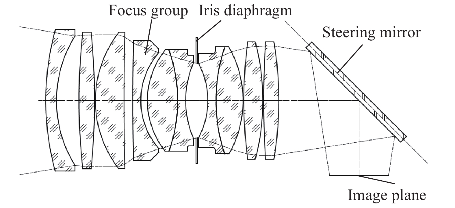
Parameter Value Focus/mm 65 FOV angle/(°) 14.72×12.43 F-number 1.8 MTF@77 lp/mm ≥0.40 Distortion ≤1% 依据光学系统参数进行光学系统设计,其结构图如图1所示。采用大相对孔径,F数低至1.8,配合大口径可变光圈,保证镜头的宽动态范围。65 mm焦距匹配6.5 μm像元尺寸可保证相机0.1 m(航高1 km)地面像元分辨率。通过移动一片透镜的方式进行光学调焦,补偿因成像距离和温度变化引起的离焦,保证清晰成像。光学系统具有较长后工作距,用于设置45°反射镜折转光路,压缩系统体积,同时反射镜进行高速摆动,补偿扫描像移。

图 1 光学系统图
Figure 1. Optical system diagram
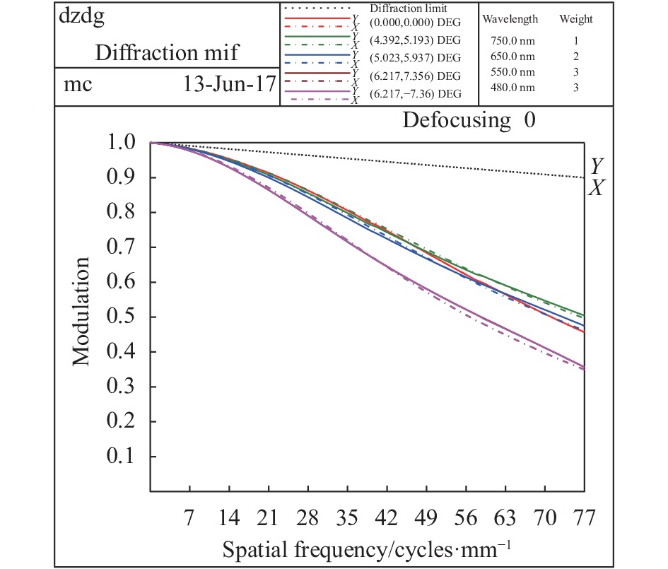
对光学系统的成像质量进行了分析,图2给出了77 lp/mm时系统的MTF曲线,可以看出系统中心视场MTF值达到0.45,保证了较高的成像清晰度。
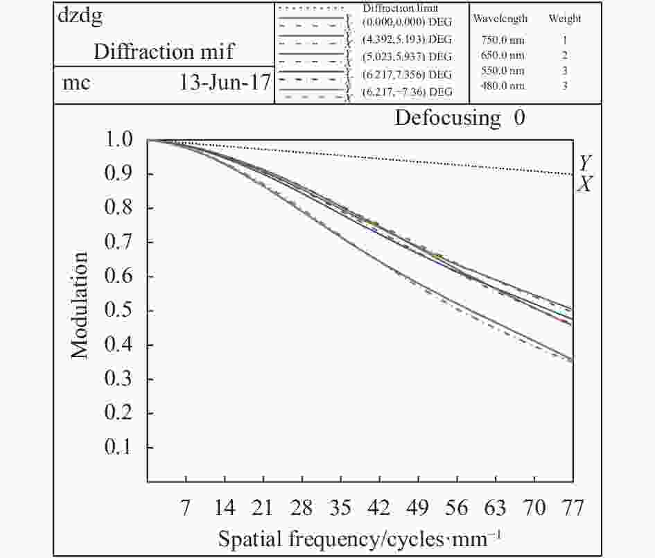
图 2 系统调制传递函数曲线
Figure 2. MTF curve of the system
-
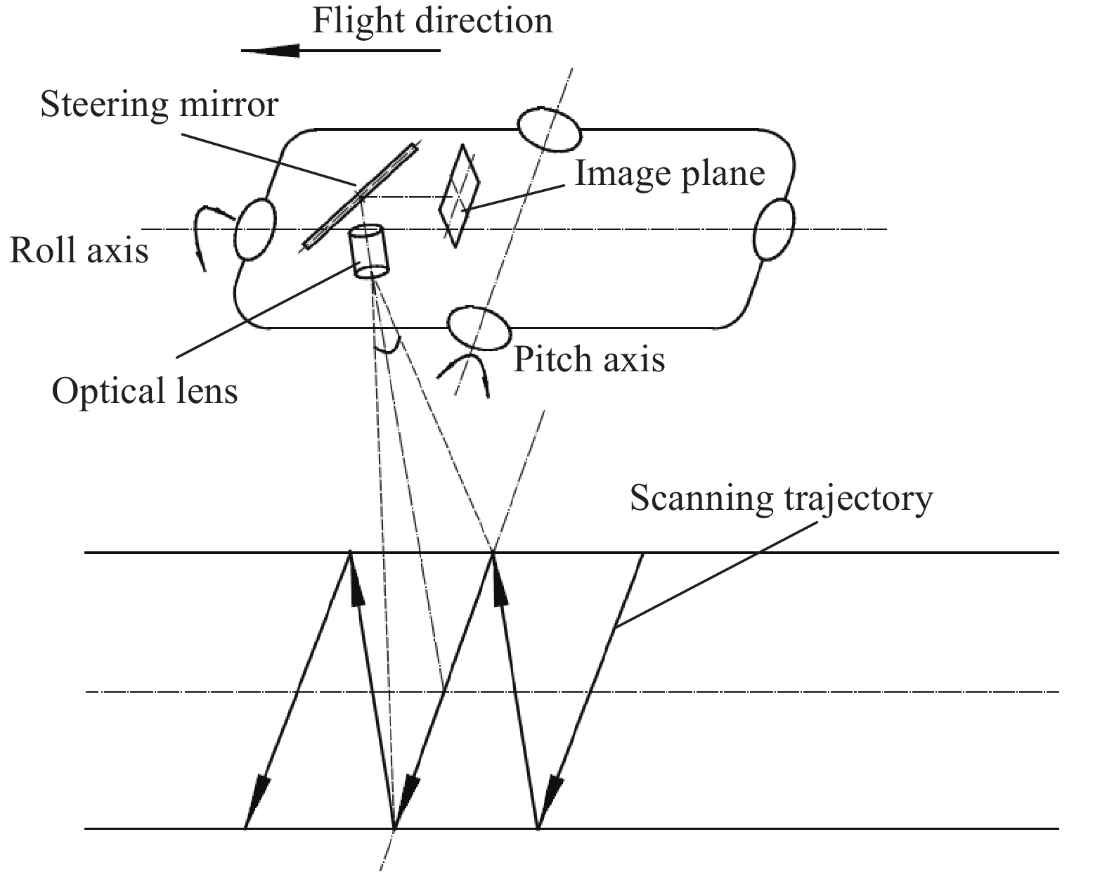
低照度宽幅相机采用大相对孔径、高分辨率光学系统匹配高灵敏度、高动态范围的科学级CMOS成像芯片,通过探测器制冷方式进一步减小探测器噪声,提高成像系统的低照度成像能力。基于总体两轴光电稳定平台,采用扫描成像工作模式;相机安装于稳定平台的横滚框架上,镜头对地成像,工作时稳定平台的横滚轴带动相机沿飞行旁向进行±56°扫描,每个扫描周期(一个来回)拍摄18幅图像。相机工作过程示意图如图3所示。飞机速高比≤0.04时,所获取的图像航向和旁向重叠率均不小于10%,通过图像拼接,实现3倍航高收容宽度。相机扫描过程中产生的像移采用快速振镜进行光学补偿。

图 3 相机工作过程示意图
Figure 3. Schematic diagram of camera working process
-
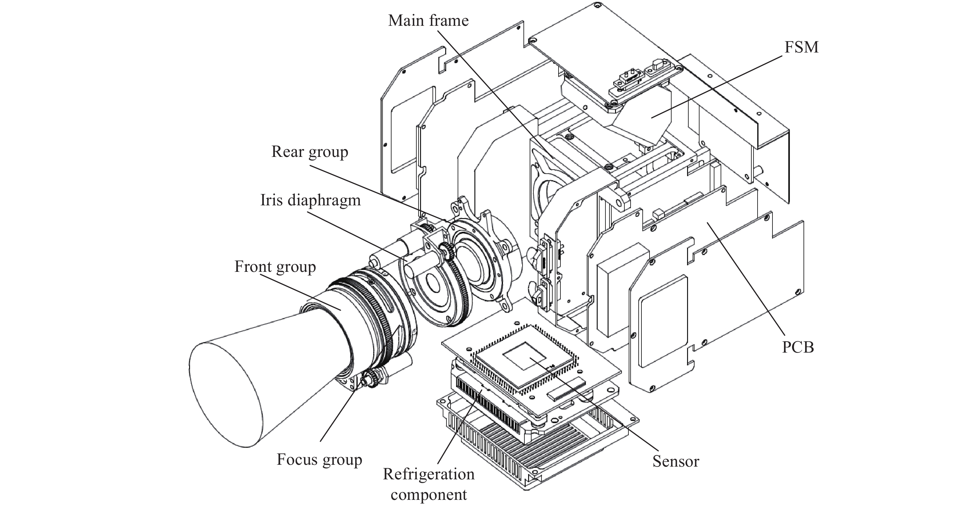
低照度相机总体分为光学成像镜头和电子学成像系统,镜头由前镜组、调焦镜组、光阑调整组件、后镜组及振镜组件组成;电子学成像系统包括制冷焦平面组件以及相关图像处理和电机控制PCB板。其爆炸示意图如图4所示。主框架是整个系统的主体支撑部件。光学镜头固定于主框架前端,前后镜组均通过定心工艺装配,实现同轴度0.008 mm。调焦镜组由凸轮机构驱动,其轴向位移分辨率为0.01 mm,可以满足光学调焦的需要。镜头中部设置有齿轮驱动的可变光阑组件,可实现0~50 mm通光孔径连续变化。振镜组件和焦平面组件安装于主框架内部。振镜的初始安装位置通过经纬仪和十字分划板工装进行装调,以保证反射镜与光轴夹角满足45°。焦平面制冷组件的制冷方式为三级半导体制冷,采用真空封装方式将探测器芯片与制冷器封装在真空腔体内,制冷器的热端设置散热片,通过风扇的方式强制风冷保证热端具有良好的散热性。在主框架两侧均布置有异型PCB板,提高空间利用率,实现系统的轻小型化。相机实际包络尺寸为190 mm×140 mm×140 mm,质量仅为2800 g。

图 4 相机爆炸图
Figure 4. Explosive view of the camera
-
相机在摆扫成像时由于像移问题限制了曝光时间,故要实现低照度成像难度较大,引入的像移补偿机构会引起像旋,经过分析,曝光时间大于1 ms时系统传函下降明显,影响成像效果,因此系统最长曝光时间应不大于1 ms。为保证在10 lx低照度环境下的成像能力,相机应在曝光时间1 ms时具有较高信噪比。
光学系统F数1.8,波段范围为480~750 nm,选用仙童公司科学级CMOS 图像传感器,其主要性能参数见表2。
表 2 CMOS传感器参数
Table 2. Parameters of the CMOS sensor
Parameter Value Active array size 2560×2160 Pixel size/μm 6.5 Full well capacity 30 000e Peak QE 55% Read noise 2e (RMS) Dark current 35e/pixel·s−1@20 ℃ $$\begin{split} \\ SNR = 20\lg \left( {\frac{{{N_{{\rm{signal}}}}}}{{{N_{{\rm{noise}}}}}}} \right) \end{split}$$ (1) 式中:
${N_{{\rm{signal}}}}$ 为探测器收集的信号电子数;${N_{{\rm{noise}}}}$ 为探测器的噪声电子数。曝光时间
${t_{int}}$ 内探测器所获取目标的总辐照量为:$$ Q={{\varPhi }_{ed}}\cdot {{t}_{int}}\cdot {{A}_{s}}=\frac{\pi }{4{{F}^{2}}}\cdot L\cdot {{\tau }_{o}}\cdot {{t}_{int}}\cdot {{A}_{s}}$$ (2) $$L={E\cdot \rho \cdot {{\tau }_{a}}}/{\pi }\;$$ (3) 式中:
$L$ 为目标光亮度;${\tau _o}$ 为光学系统透过率(${\tau _o} = 0.78$ );${\tau _a}$ 为大气透过率(${\tau _a} = 0.7$ );${A_s}$ 为像元面积(${A_s} = 6.5 \times 6.5$ μm2);$\;\rho $ 为地面目标反射率($\;\rho = 0.2$ );$E$ 为目标照度($E = 10\;{\rm{lx}}$ )。特定波长单个光子携带大小为
${{hc} / \lambda }$ 的能量,探测器的量子效率为$\eta (\lambda )$ ,取平均波长$\overline\lambda = 600\;{\rm{nm}}$ ,量子效率$\overline\eta (\lambda ) = 0.3$ 。根据光电转换原理,积分时间内探测器产生的信号电子数:$$ {{N}_{{\rm{signal}}}}=\dfrac{Q}{h\cdot c}\displaystyle\int_{\lambda }{\eta (\lambda ){\rm{d}}\lambda }=\dfrac{Q\cdot \overline{\eta }(\lambda )\cdot \overline{\lambda }}{h\cdot c}=3\;224{{e}}$$ 成像系统的噪声主要考虑读出噪声、光子散粒噪声、暗电流噪声和量化噪声,即:
$${N_{{\rm{noise}}}} = \sqrt {\sigma _{{\rm{read}}}^2 + \sigma _{{\rm{shot}}}^2 + \sigma _{{\rm{dark}}}^2 + \sigma _{{{AD}}}^2} $$ (4) 根据芯片数据手册,CMOS的读出噪声
${\sigma _{{\rm{read}}}} = $ $ 2e$ 。探测器在曝光时间1 ms时暗电流噪声为$0.003\;5e$ 。经过试验验证,探测器温度每降低6~7 ℃,暗电流噪声减少1倍,采用制冷手段将探测器温度控制在−10 ℃,其暗电流噪声可以忽略。光子散粒噪声标准偏差近似等于信号电子数的平方根,即$\sigma _{{\rm{shot}}}^2 = {N_{{\rm{signal}}}}$ 。A/D 量化噪声与探测器满阱电荷${N_{{\rm{FW}}}}$ 和量化位数${B_{{\rm{bit}}}}$ 有关,其标准偏差表示为:$${{\sigma }_{AD}}=\frac{{{N}_{{\rm{FW}}}}}{{{2}^{\left( 1+{{B}_{{\rm{bit}}}} \right)}}\cdot \sqrt{3}}=4.22e$$ 则
${N_{{\rm{noise}}}} = 57e$ 。根据公式(1)计算得到成像系统的
$SNR = 35\;{\rm{dB}}$ 。在10 lx的光照条件下,当典型地物目标的$SNR \geqslant $ $ 20\;{\rm{dB}}$ ,可以满足工程应用的需要,计算结果表明该系统可以满足10 lx低照度成像。 -
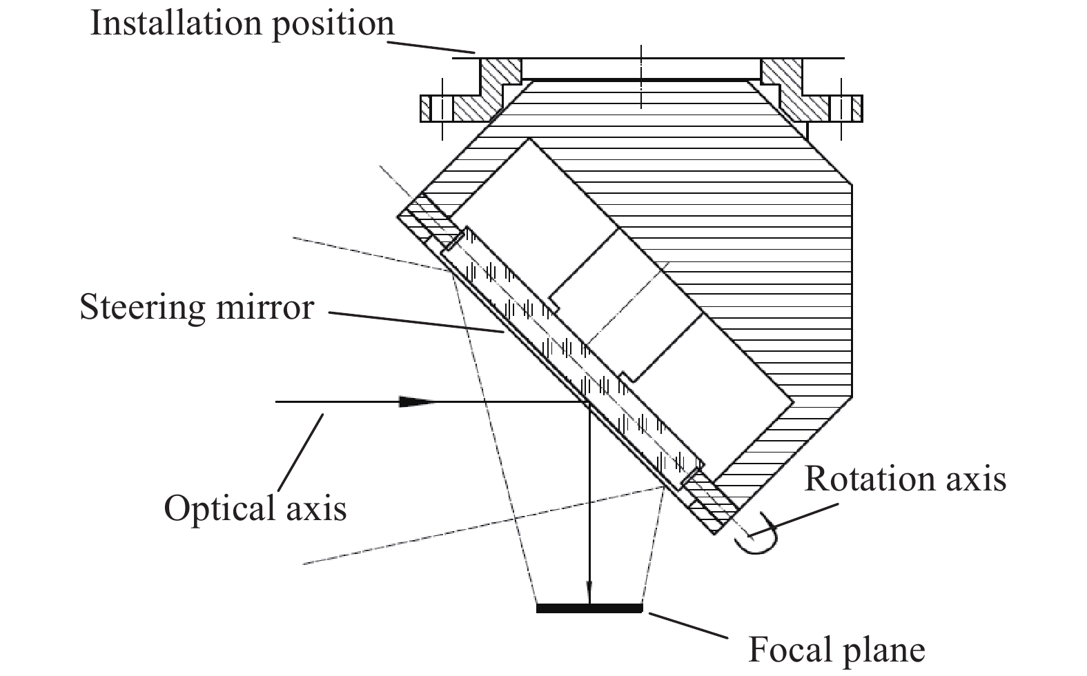
扫描像移属于运动像移,在曝光时间内,当像移量超过二分之一像元尺寸时需要对该像移进行补偿。采用高速振镜对扫描像移进行光学补偿,其工作示意图如图5所示。振镜旋转轴与系统光轴成45°夹角,这种模式可以有效减小结构总体尺寸,而且降低反射镜旋转时的转动惯量,减小驱动电机的转矩,提高系统的快速响应性以及系统的补偿精度。振镜由音圈电机驱动,具备高频响、高精度以及高可靠性的特点,能满足该设计的需求。

图 5 补偿振镜工作示意图
Figure 5. Wording diagram of compensating steering mirror
相机在扫描方向滚角速度为
$\omega = {{{{45.7}\;(^ \circ) }} / {\rm{s}}}$ ,曝光时间为1 ms,所以曝光时间内像移量为:$$\Delta =f\cdot \tan (\omega \cdot t)=0.052\ {{\rm{mm}}}$$ 探测器像元尺寸为6.5 μm× 6.5 μm,则系统扫描像移量为8个像元,所以需要进行像移补偿。
振镜转动角速度
$\omega '$ 和像移的关系为:$$\Delta =2\times d\cdot \tan ({\omega }'\cdot t)=0.052\ {{\rm{mm}}}$$ 式中:
$d$ 为振镜反射面中心到靶面距离,28 mm。可以求得振镜转动的角速度为$\omega ' = {{{{53.2}\;(^ \circ) }} / {\rm{s}}}$ ,扫描振镜的转角为0.0532°。 -
低照度相机处于较为复杂恶劣的航空机载工作环境,相机的结构稳定性是影响相机性能及寿命的关键因素。主体框架是低照度相机中的关键零件,担负着连接镜头、固定电子学组件及与外部平台连接的重要作用。其结构尺寸较大,材料选用7系超硬铝,结构形式采用加强筋的框架设计,轻量化设计后质量为350 g。主框架的结构强度直接影响整机的稳定性,需对其机械强度进行分析。根据HB.6167.6-2014振动试验的要求,分析其固有频率及在冲击振动条件下的应力与应变。
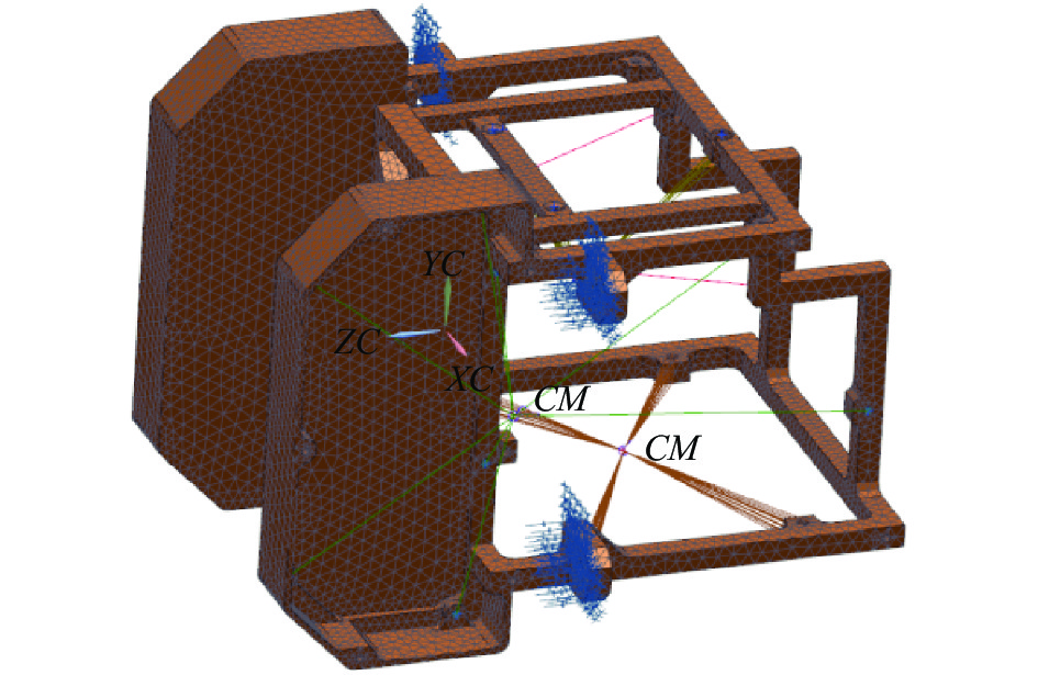
利用Nastran软件对主框架进行有限元分析,对主框架进行有限元网格划分,采用大质量体方法对连接关系进行简化。固定于其上的镜头组件、振镜组件、焦平面组件及各个电路板均用大质量单元替代,各个大质量单元赋予各个组件实际质量值,且均位于各个组件质心位置。对4个安装耳进行固定约束。划分完成后的有限元模型如图6所示。

图 6 主框架有限元模型
Figure 6. Finite element model of main frame
对主框架进行模态分析,得到其前6阶固有频率,表3给出了前6阶固有频率的值,图7给出了前6阶模态形态。第一阶固有频率为643 Hz,表明其在运输及工作过程中不会发生低频共振。从前6阶振型可以看出,前3阶振型均为负载受拉伸而引起的振动,其对系统振动贡献较大,而从第4阶振型开始出现扭转振动,其对系统振动贡献较小,表明主框架具有较好的刚性。
表 3 固有频率
Table 3. Natural frequency
Mode number 1 2 3 4 5 6 Frequency/Hz 643 1053 1220 1611 1733 2038 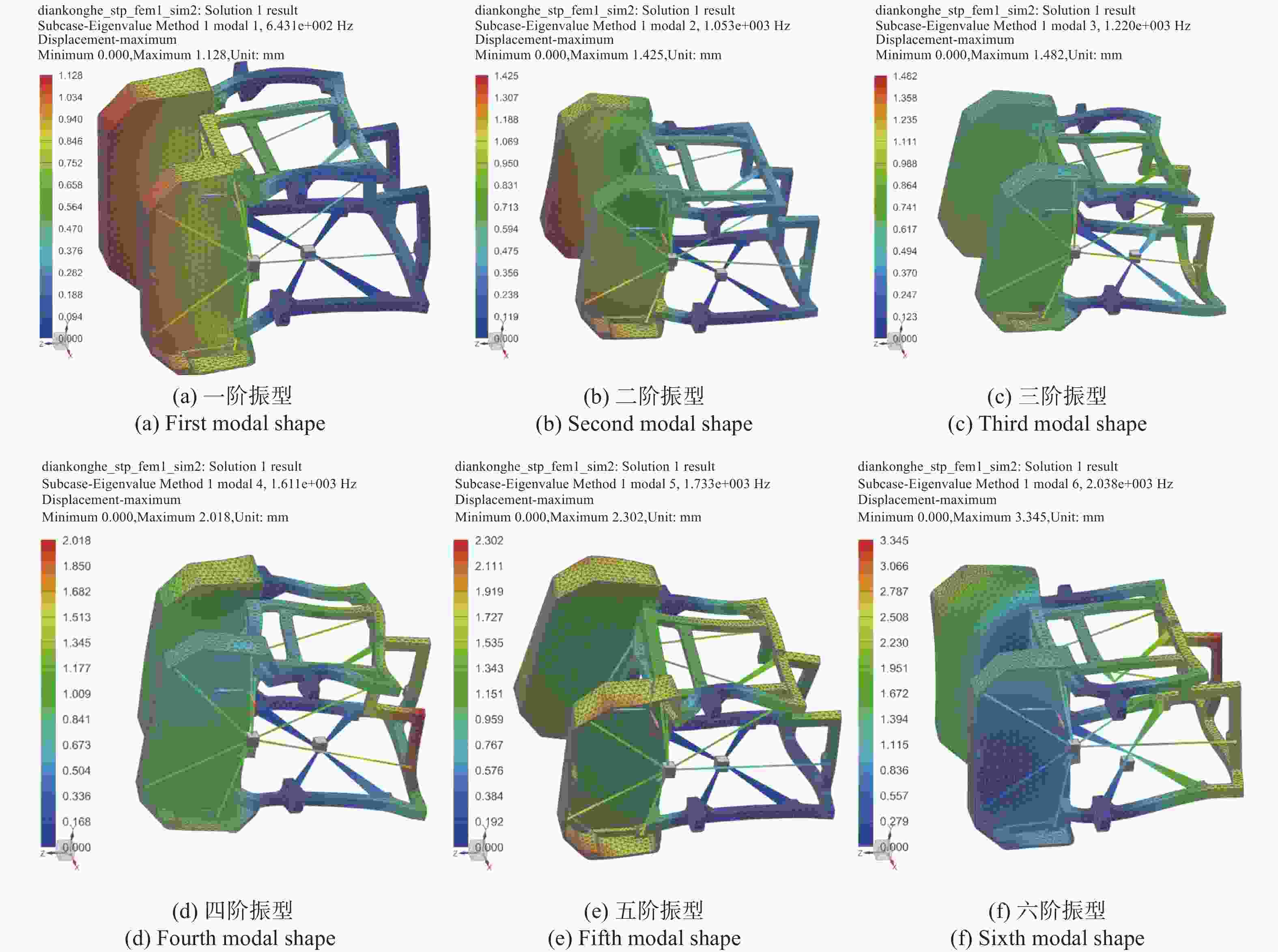
图 7 主框架前六阶振型
Figure 7. First six modal shapes of the main frame
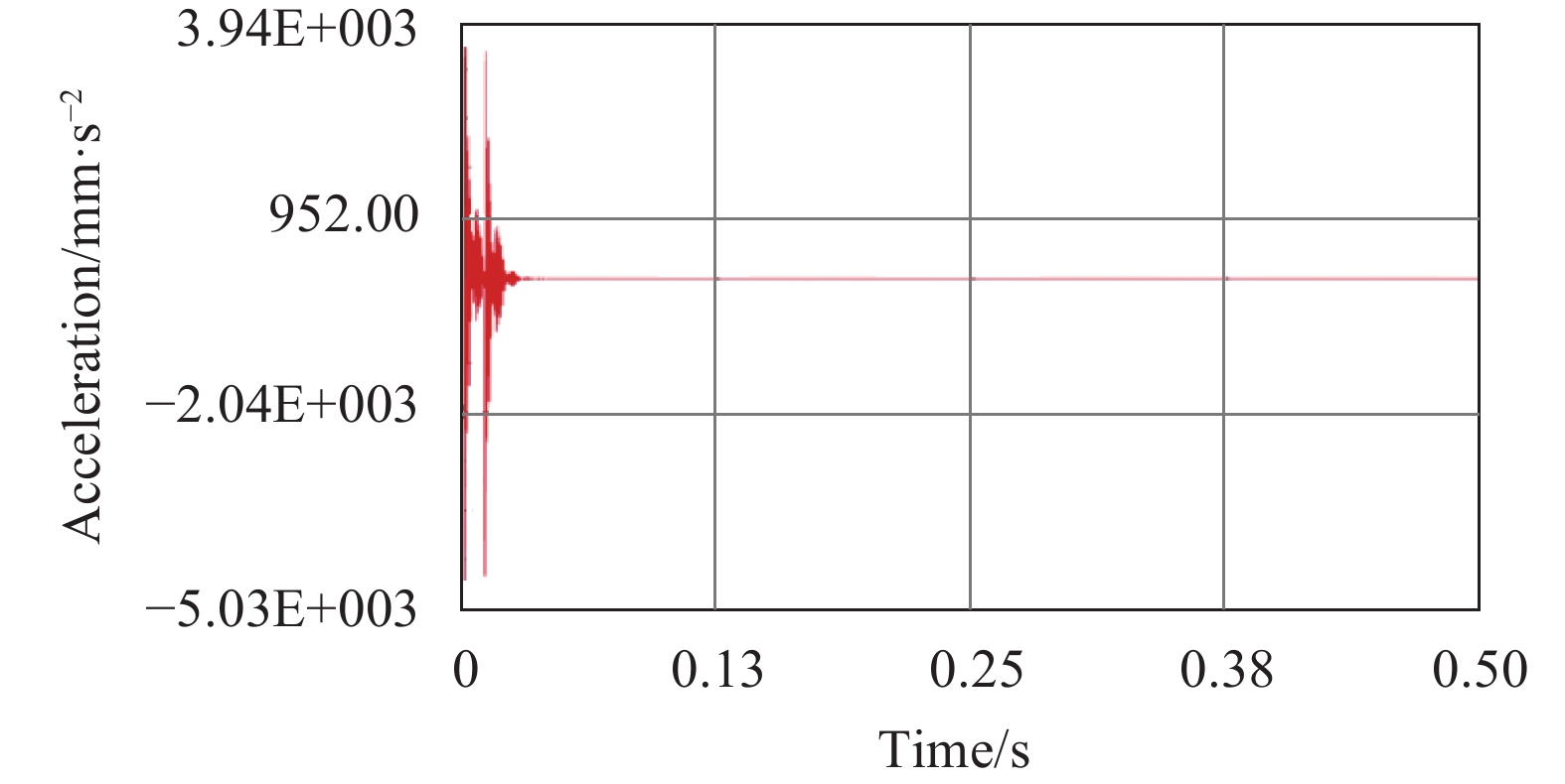
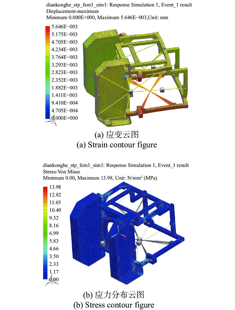
冲击振动试验条件量级较大,主要用来考核系统对极难应力的承受能力。对主框架进行冲击振动响应分析,更容易发现结构设计的薄弱处。航空力学环境冲击波形为后峰锯齿波,峰值加速度20 g,持续时间11 ms。对主框架进行冲击响应分析,图8给出了沿光轴方向有限元模型镜头连接处的冲击响应曲线,分析时长为0.5 s。图9给出了冲击条件下,主框架在响应过程中,最大应变及应力云图分布。

图 8 冲击响应曲线
Figure 8. Curve of shock response

图 9 冲击响应最大应力与应变云图
Figure 9. Contour figures of the maximum stress and strain of shock response
由分析结果可知,主框架在沿光轴方向上受冲击后的最大应力为13.98 MPa,远小于7075材料的屈服强度455 MPa,且大多出现在螺钉连接处。受冲击所产生的最大应变为5.64 μm,该量级对光学系统不会产生实质的影响。表明主框架结构形式可以满足航空载荷力学试验条件要求的基本冲击试验。
-
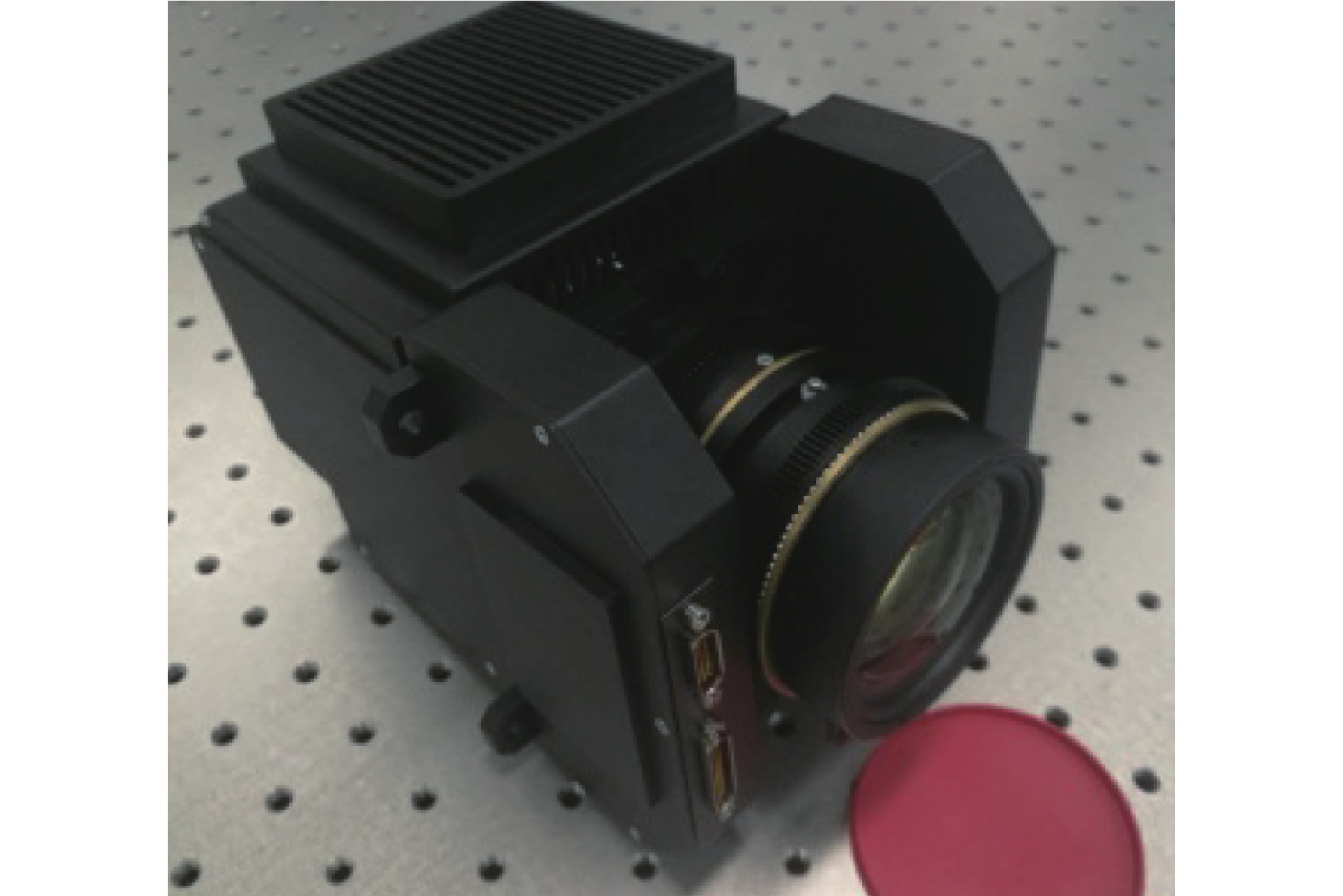
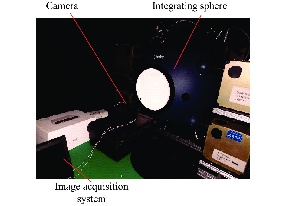
依据上述设计方法完成整机加工装配,实物效果如图10所示。对系统进行了成像动态范围测试,以验证相机的照度适应范围,测试系统如图11所示。分别对目标照度10 lx和100000 lx进行图像采集,读取图像平均灰度值,测试结果见表4。目标照度10 lx时,相机采集图像灰度值仍远大于背景灰度,而在目标照度10000 lx时,图像也未饱和,表明相机的成像照度范围满足指标要求。对装配完成的镜头的中心视场MTF进行了测试,数据结果见表5。可知当空间频率为77 lp/mm时,光学系统中心视场MTF远大于0.45,完全可以保证相机的成像质量。

图 10 低照度宽幅航空相机
Figure 10. Wide view aerial camera system in low-light

图 11 成像动态范围测试系统
Figure 11. Test system of dynamic imaging range
表 4 成像动态范围测试结果
Table 4. Test results of the dynamic imaging range
Luminance value/lx 10 100000 Gray value 191.2 819.0 表 5 MTF 测试结果
Table 5. Results of the MTF tests
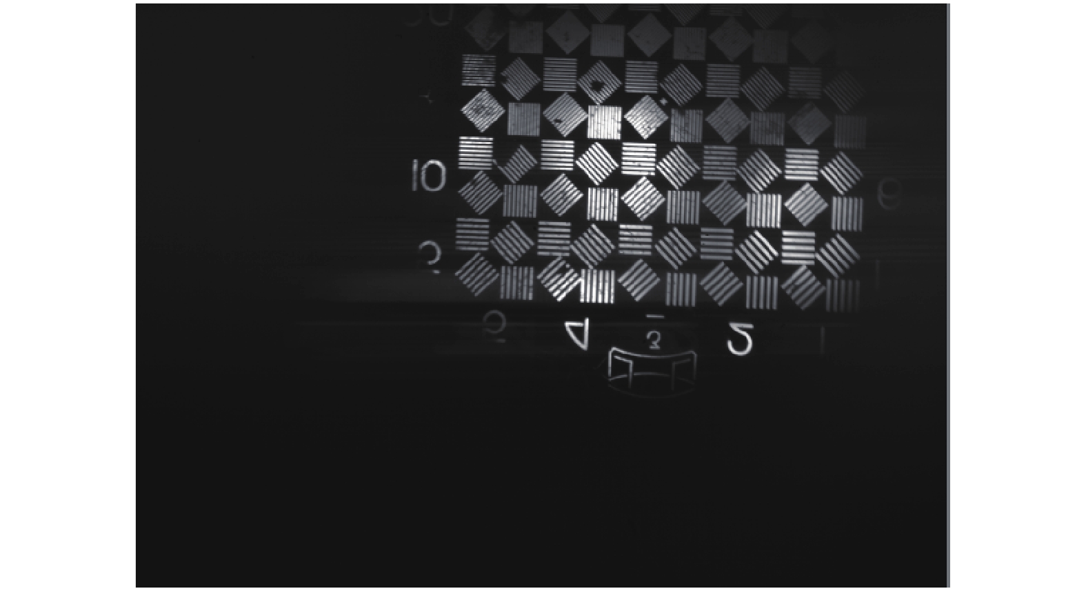
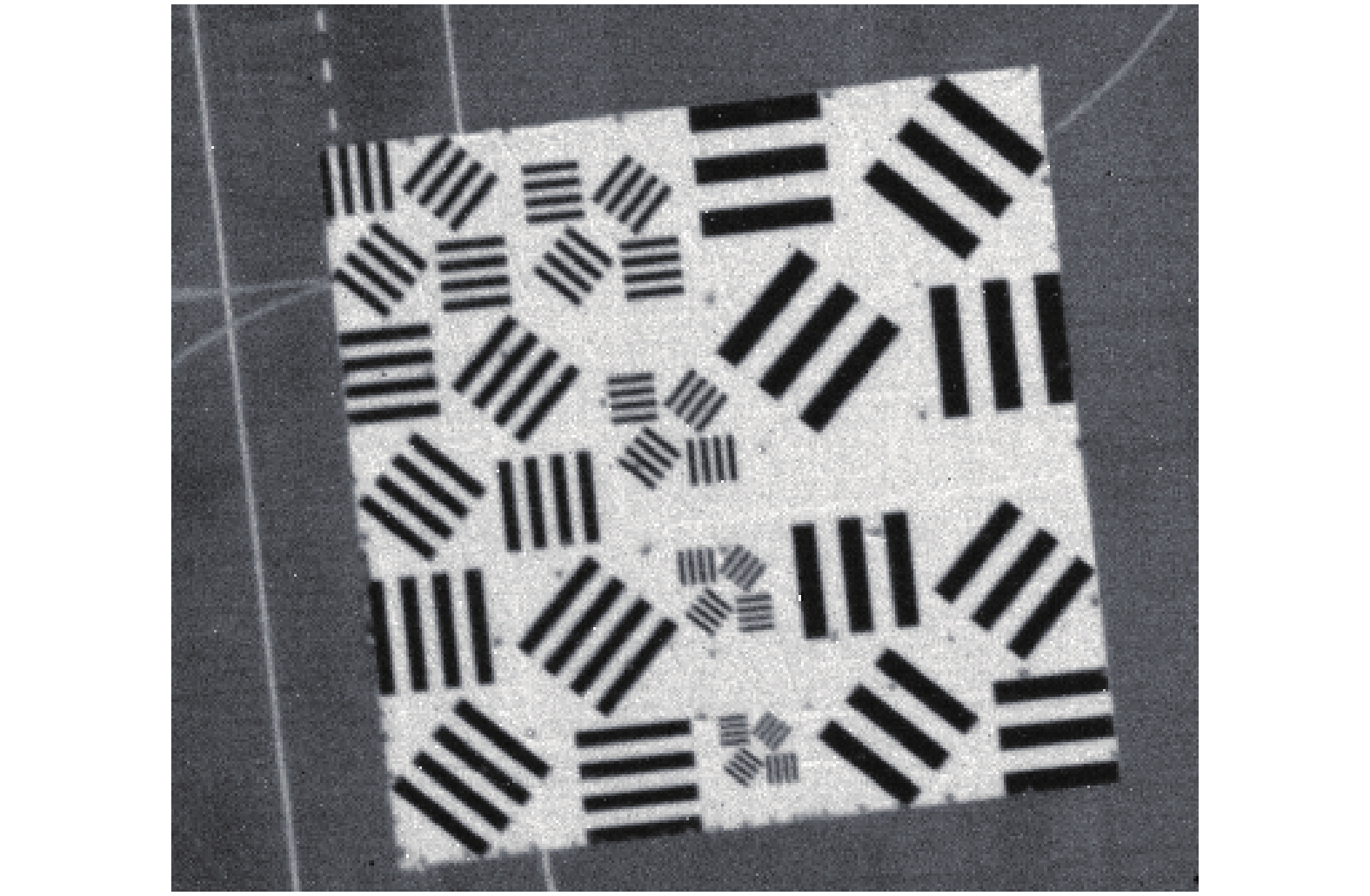
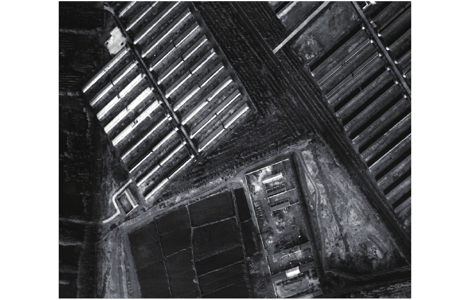
Focus F-number 60 lp/mm 70 lp/mm 80 lp/mm 90 lp/mm 65 mm 1.8 0.589 0.532 0.459 0.39 对低照度相机的分辨率和成像效果进行了一系列实验室测试和航拍动态试验。图12所示为在20 lx目标照度条件下对300 mm平行光管鉴别率板成像图片。图13所示为有人机平台飞行拍摄试验靶标完整图像,图14所示为拍摄靶标局部放大图像,图15所示为所获取的村庄及农田场景图像。试验时间为2020年6月凌晨5:30,试验地点为陕西蒲城,飞行航高2 000 m,航速220 km/h。从获取的图像可以看出,在低照度条件下相机对鉴别率板条纹分辨清晰,边缘成像锐利。外景图像中测试靶标条纹、机场跑道房屋、农田及树木等均清晰可见,表明相机的成像质量优良。经测算,相机达到了0.1 m (航高1 km)地面像元分辨率。通过飞行试验也进一步验证了相机的稳定性和可靠性。为验证系统的低照度成像能力,与常规相机做了对比试验,试验结果如图16所示,表明低照度宽幅航空相机具有较高的低照度环境适应性。
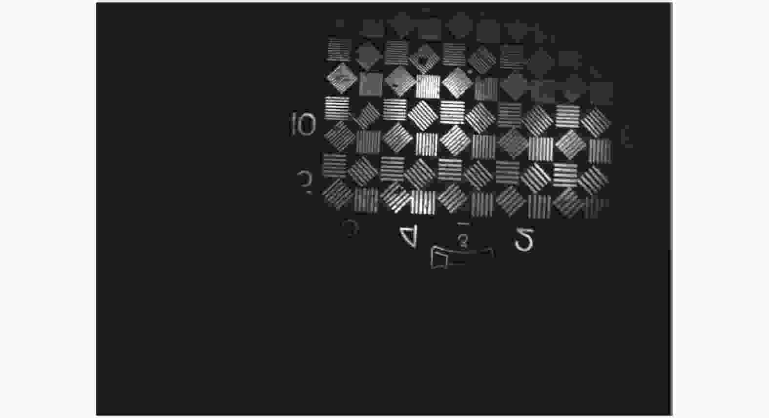
图 12 实验室测试图像
Figure 12. Image of laboratory test

图 13 航拍试验靶标完整图像
Figure 13. Complete aerial image of the test target

图 14 靶标局部放大图像
Figure 14. Partial enlarged view of the target

图 15 村庄及农田场景图像
Figure 15. Image of village and farmland
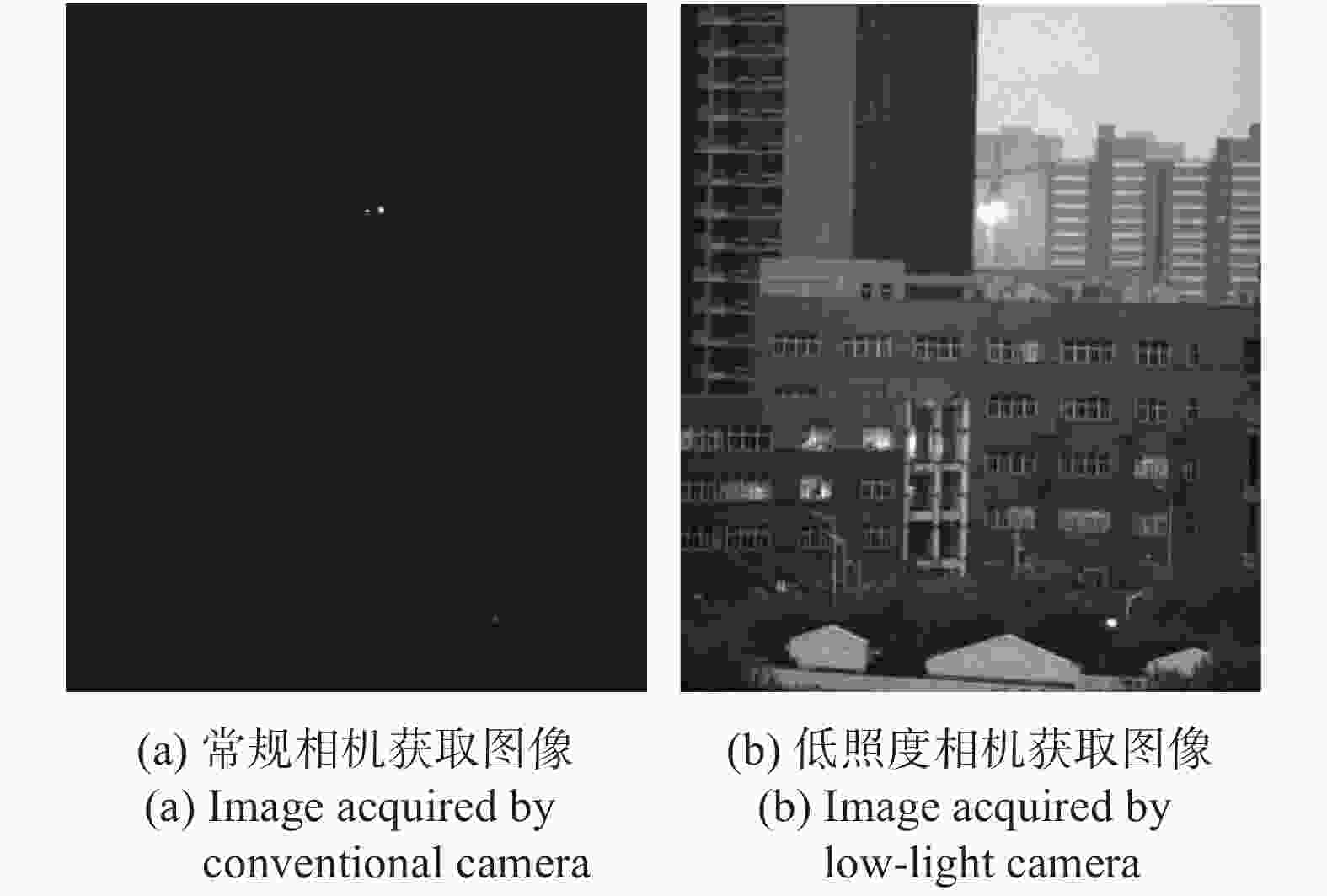
图 16 低照度成像对比试验
Figure 16. Low-light imaging contrast test
-
文中对可适应于低照度环境的宽动态航空相机系统设计进行了研究。采用大相对孔径光学系统设计,结合相机摆扫成像的工作模式,通过振镜像移补偿实现了相机在低照度条件下的宽幅成像能力。通过摆扫成像,相机可获得3倍航高的大幅宽高分辨率图像,有效提高了航空影像信息的获取能力。在室内10 lx低照度条件下,所获取的图像仍具有较高对比度。该航空相机系统结构紧凑,成像质量优良,结构稳定性高。通过一系列实验室测试和航拍动态试验,表明该低照度宽幅航空相机满足设计指标要求。文中的设计和研究结果对于航空相机领域的发展具有一定意义。
Design of wide view aerial camera system in low-light
-
摘要: 为了满足低照度环境下航空影像信息快速获取的需求,对一种低照度宽幅成像系统进行了研究。基于相机摆扫成像的工作模式,明确了采用大相对孔径低畸变的光学系统,配合真空制冷的低噪声高灵敏度CMOS探测器成像,并通过高速振镜进行扫描像移补偿的技术路线。详细阐述了相机机械构型的设计思路,总结了一套可工程应用的低照度成像能力计算方法。研究了振镜补偿像移的基本原理,并对相机主体框架进行了仿真分析计算。依据该设计和研究结果,完成了低照度宽幅航空相机的加工装配。该相机具有0.1 m (航高1 km)地面像元分辨率, 成像照度适应范围为10~100000 lx,并且在速高比≤0.04时,可实现3倍航高的大收容宽度。系统的成像质量优良,实测镜头在77 lp/mm时,中心视场传递函数大于0.45。实验室和外场飞行试验所获取的图像清晰,对比度和分辨率高,可以满足使用需求。同时,该相机实际包络尺寸为190 mm×140 mm×140 mm,质量仅为2800 g,具有轻小型的特点。Abstract: In order to meet the requirements of quick acquisition of aerial image information in low light condition, a wide view imaging system which can be adapted to low-light environments was studied. Based on the camera working mode of frame-sweep imaging, the technology route of adopting a large relative aperture and low distortion optical system, combining a low-noise and high-sensitivity CMOS detector with vacuum cooling, and compensating the scanning image motion by high-speed steering mirror was clarified. The design ideas of the mechanical configuration of the camera were explained in detail, and a set of calculation methods of imaging capabilities in low-light which can be applied in engineering were summarized. The basic principle of compensating image motion with steering mirror was studied, and the main frame of the camera was simulated, analyzed and calculated. According to the design and research results, the processing and assembly of the wide view aerial camera in low-light were completed. The camera has a ground sample distance (GSD) of 0.1 meters (height 1 km), and adaptable illumination range of 10-100000 lx, and a large view width of 3 times the height when the speed to height ratio is less than 0.04. The imaging quality of the system is excellent, and test results show that the MTF of the center field of view at 77 lp/mm is greater than 0.45. The images obtained from laboratory and field flight tests are clear, with high contrast and resolution, which can meet the requirements of use. At the same time, the system is 190 mm×140 mm×140 mm in actual size and 2800 g in weight, which is light and small.
-
Key words:
- aerial camera /
- low-light /
- simulation analysis /
- wide view /
- imaging
-
图 9 冲击响应最大应力与应变云图
Figure 9. Contour figures of the maximum stress and strain of shock response
表 1 光学系统参数
Table 1. Parameter of optical system
Parameter Value Focus/mm 65 FOV angle/(°) 14.72×12.43 F-number 1.8 MTF@77 lp/mm ≥0.40 Distortion ≤1%  下载: 导出CSV
表 2 CMOS传感器参数
Table 2. Parameters of the CMOS sensor
Parameter Value Active array size 2560×2160 Pixel size/μm 6.5 Full well capacity 30 000e Peak QE 55% Read noise 2e (RMS) Dark current 35e/pixel·s−1@20 ℃
下载: 导出CSV
表 4 成像动态范围测试结果
Table 4. Test results of the dynamic imaging range
Luminance value/lx 10 100000 Gray value 191.2 819.0
下载: 导出CSV
表 5 MTF 测试结果
Table 5. Results of the MTF tests
Focus F-number 60 lp/mm 70 lp/mm 80 lp/mm 90 lp/mm 65 mm 1.8 0.589 0.532 0.459 0.39
下载: 导出CSV
-
[1] Li Haixing, Hui Shouwen, Ding Yalin. Development and key techniques of optical mapping equipment in foreign airborne [J]. Journal of Electronic Measurement and Instruction, 2014, 28(5): 469-477. (in Chinese) [2] Zhao Jianchuan, Zhang Runqi, Wang Jie, et al. Research on aerial camera imaging technology [J]. Infrared Technology, 2020, 42(2): 101-114. (in Chinese) doi: 10.3724/SP.J.7100931192 [3] Ren Liyan, Li Yingcheng, Xiao Jincheng, et al. Multi-source data integration and intelligent service of surveying and mapping UAV for disaster scene [J]. Science of Surveying and Mapping, 2020, 45(12): 139-144. (in Chinese) [4] Hu Haili, He Lei, Zhang Yong, et al. Imaging experiments for weak small target in low-light-level background [J]. Infrared and Laser Engineering, 2020, 49(9): 20190569. (in Chinese) doi: 10.3788/IRLA20190569 [5] Liu Chao, Zhang Xiaohui. Deep convolutional autoencoder networks approach to low-light level image restoration under extreme low-light illumination [J]. Optics and Precision Engineering, 2018, 26(4): 951-961. (in Chinese) doi: 10.3788/OPE.20182604.0951 [6] Wu Haibing, Tao Shengxiang, Zhang Liang, et al. Tricolor acquisition and true color images fusion method under low illumination condition [J]. Journal of Applied Optics, 2016, 37(5): 673-679. (in Chinese) [7] Lu Pengluo, Li Yongchang, Jin Longxu, et al. Image motion velocity field model of space camera with large field and analysis on three-axis attitude stability of satellite [J]. Optics and Precision Engineering, 2016, 24(9): 2173-2182. (in Chinese) doi: 10.3788/OPE.20162409.2173 [8] Li Yongchang, Jin Longxu, Li Guoning, et al. Image motion velocity model and compensation strategy of wide-field remote sensing camera [J]. Geomatics and Information Science of Wuhan University, 2018, 43(8): 1278-1286. (in Chinese) [9] Zhong Hui. Focal plane alignment for remote sensing camera with dual focal plane of large field of view interval [J]. Infrared and Laser Engineering, 2021, 50(2): 20200172. (in Chinese) doi: 10.3788/IRLA20200172 [10] Zheng Lina, Li Yanwei, Yuan Guoqin, et al. Automatic focus plane detection of aerial remote camera based on Visibility [J]. Infrared and Laser Engineering, 2019, 48(4): 0417001. (in Chinese) doi: 10.3788/IRLA201948.0417001 [11] Wang Chunyu, Wang Cong, Niu Jinchuan, et al. Passive athermal integrated design and verification analysis for the optical lens of aerial camera [J]. Infrared and Laser Engineering, 2021, 50(3): 20200220. (in Chinese) [12] 王伟. 多波段短波红外相机光学系统设计与成像质量评估[D]. 长春: 中国科学院大学, 2020. Wang Wei. Optical system design and imaging quality evaluation of multi-band short-wave infrared camera[D]. Changchun: University of Chinese Academy of Sciences (Changchun Institute of Optics, Fine Mechanics and Physics, Chinese Academy of Sciences), 2020. (in Chinese) [13] 张元涛. 空间高灵敏度大动态范围微光成像技术研究[D]. 上海: 中国科学院大学, 2018. Zhang Yuantao. Research on technologies of high sensitivity and large dynamic range low light level imaging in space[D]. Shanghai: University of Chinese Academy of Sciences (Shanghai Institute of Technical Physics, Chinese Academy of Sciences), 2018. (in Chinese) -

 点击查看大图
计量
- 文章访问数: 184
- HTML全文浏览量: 62
- PDF下载量: 60
- 被引次数: 0


