


-
语音是一种重要的信息资源,它既可以用于边界入侵检测如车辆或人员[1],公共区域环境监控与事件取证,如银行、地铁、飞机场、电梯、广场,也可作为视频监控与追踪的一种互补的信息资源来实现对人员及事件的准确追踪。激光相干外差探测是一种非接触语音信息获取技术,具有灵敏度高,探测距离远,抗干扰等优点被广泛应用。2011年,中国科学院半导体研究所首次基于相位生成载波(Phase Generated Carrier,PGC)技术自主研制了激光语音获取系统,可实现100 m金属材料的有效语音获取[2]。2017年,中国科学院长春光学精密机械与物理研究所提出激光语音检测系统反正切补偿算法,可实现35 m语音获取[3];同年,该单位提出了基于激光相干的全光纤语音获取系统,实现对喉咙处70 m处的语音获取[4]。
研究发现,微分交叉相乘解调(PGC-differential-cross-multiplying,PGC-DCM)算法解调出的语音信号含有光强信息[2],该光强信息与目标后向光散射特性有关[5],在对目标物后向光散射特性研究分析后,发现受后向光散射特性影响系统有效入射角度不大于40°,目标物表面粗糙度需小于6.3 rad,金属目标物优于非金属目标,发现目标物的折射率(目标材质)、系统入射到目标物角度、目标物表面粗糙度都会影响目标物的后向反射光的光强度,测试结果显示,该光强度将直接影响系统信噪比[5],从而限制激光相干语音获取技术在实际应用发挥的效果。
基于PGC-DCM解调算法存在的易受光扰动影响问题,美国海军实验室[6]、肯特大学[7]、中国科学院半导体研究所[8]、哈尔滨工程大学[9]提出了反正切PGC-Arctan算法,PGC-Arctan算法解调出来的信号不受光强影响,但是由于正切函数为单调函数,且其范围为
$( - {\raise0.5ex\hbox{$\scriptstyle \pi $}\kern-0.1em/\kern-0.15em\lower0.25ex\hbox{$\scriptstyle 2$}},{\raise0.5ex\hbox{$\scriptstyle \pi $}\kern-0.1em/\kern-0.15em\lower0.25ex\hbox{$\scriptstyle 2$}})$ ,所以该解调方法只能测量幅度较小的信号,当声音的振动幅度大于${\raise0.5ex\hbox{$\scriptstyle \pi $}\kern-0.1em/\kern-0.15em\lower0.25ex\hbox{$\scriptstyle 2$}}$ 时,系统解调出来的信号存在失真,不能正确的解调出语音信息,系统解调出的信号存在较高的谐波失真。S.C.Huang等提出了一种基于带通滤波消光算法消除光扰动,不受单调函数限制,但其运算量较大,谐波失真较高[10]。Shuai Zhang等人提出了利用参考补偿方法来消除光强扰动[11]。Liping Yan等人提出了一种用正弦和三角信号组合消除光强扰动[12]。天津理工大学提出了基于基频混频的不对称相除的微分自相乘PGC解调算法,消除光强扰动对解调结果的影响[13]。深圳大学提出了一种新型的单路微分相除(PGC-SDD)解调算法[14]。综上可知,光强扰动影响对信号解调时不容忽视的,基于此,为了进一步提高激光语音获取系统实用性,文中提出一种基于相位生成载波解调的归一化自相除消光强扰动解调算法。
-
通过激光外差干涉获得待解调语音信号表达式为:
$$I = A + B\;{\rm{cos}}[C\;{\rm{cos}}\;{\omega _c}\;t + D{\rm{cos}}({\omega _c}\;t) + \phi (t)]$$ (1) 式中:A为干涉场背景光强引起的直流信号,mW;B为干涉光强大小,mW,
$B = \sqrt {{I_s}{I_r}} $ ,其中${I_s}$ 为返回信号光光功率,mW;${I_r}$ 为参考光光功率,mW;C cos(ωct)为调制器(EOM)引起的相位差,其中C为调制幅度,rad;${\omega _{\rm{c}}}$ 为载波角频率,Hz;t为时间,s;D cos(ωst)为语音信号,其中D为语音引起目标物振动幅度,rad,${\omega _{\rm{s}}}$ 为语音引起目标物振动角频率,Hz;$\phi (t)$ 为初始相位差。为方便后续信号处理表述,令θ(t)=D cos(ωst)+ϕ(t),表述为待测语音信号和初始相位差的合成量,rad。鉴于激光语音获取系统的工作原理,根据漫反射大目标激光雷达作用距离方程可知,返回信号光功率
${I_s}$ [15]:$${I_s} = \frac{{{I_{\rm{i}}}T_A^2{\sigma _{pq}}{D^2}}}{{4{r^2}}}{\eta _t}{\eta _r}$$ (2) 式中:
${\sigma _{pq}}$ 为目标后向散射系数;$D$ 为接收口径;TA为单程大气传输系数;ηt为光学系统发射传输系数;ηr为光学系统接收传输系数;${{r}}$ 为工作距离;${I_i}$ 为入射光功率。$$B = \sqrt {{I_s}{I_r}} $$ (3) 由公式(2)和公式(3)可知,
$$B = \sqrt {\frac{{{I_{\rm{i}}}T_A^2{\sigma _{pq}}{D^2}}}{{4{r^2}}}{\eta _t}{\eta _r}{I_r}} $$ (4) 参考基尔霍夫驻留相位近似法,假定目标物粗糙表面随机起伏服从高斯分布,其后向散射系数表达式为:
$${\sigma _{pq}} = \dfrac{{{{\left| {\dfrac{{n - 1}}{{n + 1}}} \right|}^2}}}{{2{{\left(\sqrt 2 \dfrac{\delta }{T}\right)}^2}{{\cos }^4}\theta }}\exp \left[ - \dfrac{{{{\tan }^2}\theta }}{{2{{\left(\sqrt 2 \dfrac{\delta }{T}\right)}^2}}}\right]$$ (5) 式中:
$n$ 为目标物的折射率;$\theta $ 为探测激光入射角度;$\delta $ 为随机表面起伏的高度均方根;$T$ 为表面相关长度;$\delta $ 、$T$ 决定目标物的粗糙度。由公式(4)、公式(5)可知,干涉光强B为:
$$B = \sqrt {\dfrac{{{I_{\rm{i}}}T_A^2{D^2}}}{{4{r^2}}}{\eta _t}{\eta _r}{I_r}\dfrac{{{{\left| {\dfrac{{n - 1}}{{n + 1}}} \right|}^2}}}{{2{{\left(\sqrt 2 \dfrac{\delta }{T}\right)}^2}{{\cos }^4}\theta }}\exp \left[ - \dfrac{{{{\tan }^2}\theta }}{{2{{\left(\sqrt 2 \dfrac{\delta }{T}\right)}^2}}}\right]} $$ (6) 公式(6)说明B受后向散射系数
${\sigma _{pq}}$ 影响,存在着探测角度,目标物种类,目标物表面粗糙度的后向光散射特性影响。为此,文中将开展目标后向光散射特性抑制技术研究,通过归一化自相除PGC解调算法进行消光强扰动。其解调流程如图1所示。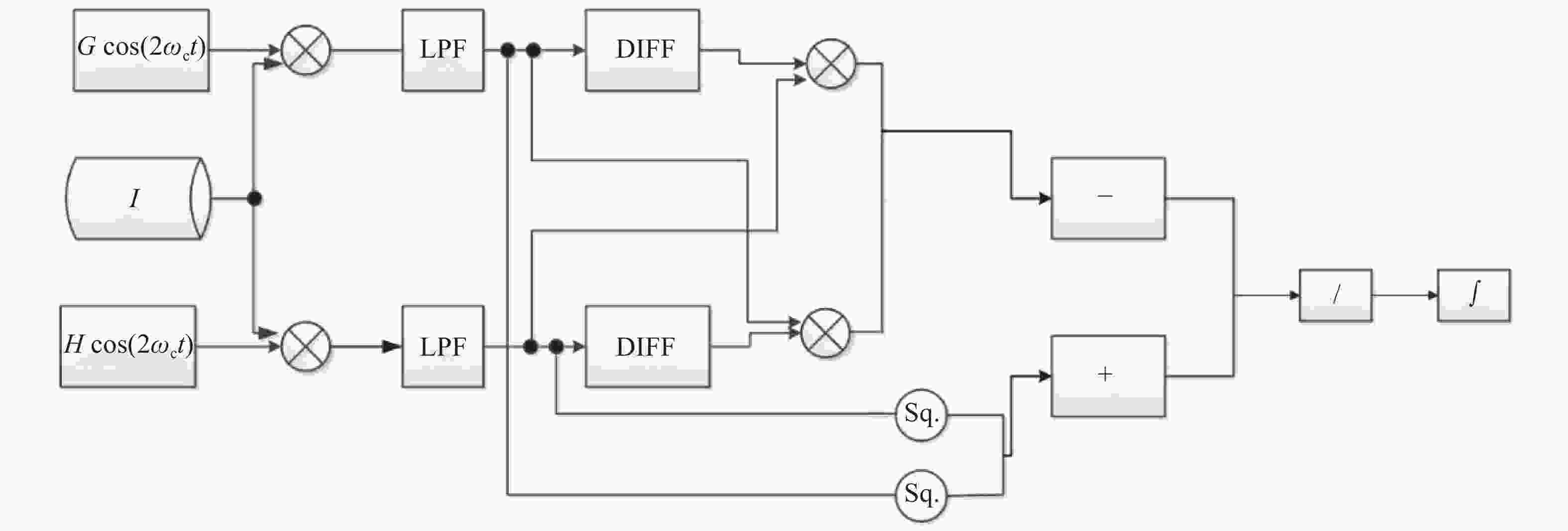
图 1 新解调算法流程图
Figure 1. Schematic of the new demodulation algorithm
图1为归一化自相除的消光强扰动新算法流程图,包含乘法器、低通滤波器、微分器、减法器、平方器、加法器以及积分器。其中一倍频载波为
$G\cos ({\omega _c}t)$ ,二倍频载波为$H\cos (2{\omega _c}t)$ 。根据此解调方法,对公式(1)用Bessel函数展开后与一倍频载波$G\cos ({\omega _c}t)$ 及二倍频载波$H\cos (2{\omega _c}t)$ 相乘,经过低通滤波器,进行平方,其公式变为:$${I_{51}} = {B^2}{G^2}{J_1}^2(C){\sin ^2}\theta (t)$$ (7) $${I_{51}} = {B^2}{H^2}{J_2}^2(C){\rm{cos}}{^2}\theta (t)$$ (8) 系统中令C的调制度为2.63 rad[4],则
${J_1}(C) = $ $ {J_2}(C)$ ,且$G = H = 1$ ,将公式(7)与(8)相加后变为:$${I_{61}} = {B^2}{G^2}{J_1}^2(C)$$ (9) 对公式(1)分别与一倍频载波
$G\cos ({\omega _c}t)$ 及二倍频载波$H\cos (2{\omega _c}t)$ 相乘,得到:$$ \begin{split} {I_1}_1 =& GA\cos {\omega _c}t + GB{J_0}(C)\cos {\omega _c}t\cos \theta (t) + \\ & {\rm{ }}BG\cos \theta (t)\sum\limits_{k = 1}^\infty {{{( - 1)}^k}} {J_{2k}}(C)[\cos (2k + 1){\omega _c}t +\\ & \cos (2k - 1){\omega _c}t] - {\rm{ }}BG\sin \theta (t)\sum\limits_{k = 0}^\infty {{{( - 1)}^k}} {J_{2k + 1}}(C)\cdot \\ &[\cos (2k + 2){\omega _c}t + \cos 2k{\omega _c}t] \\ \end{split} $$ (10) $$ \begin{split} {I_{12}} =& HA\cos 2{\omega _c}t + HB{J_0}(C)\cos 2{\omega _c}t\cos \theta (t) + \\ & {\rm{ }}BH\cos \theta (t)\sum\limits_{k = 1}^\infty {{{( - 1)}^k}} {J_{2k}}(C)[\cos 2(k + 1){\omega _c}t + \\ & \cos 2(k - 1){\omega _c}t] - {\rm{ }}BH\sin \theta (t)\sum\limits_{k = 0}^\infty {{{( - 1)}^k}}\cdot\\ & {J_{2k + 1}}(C)[\cos (2k + 3){\omega _c}t + \cos (2k - 1){\omega _c}t] \\ \end{split} $$ (11) ${I_1}_1$ 和${I_{12}}$ 经过低通滤波器后变成:$$I_{21} = - {BGJ}_{1}(C)\sin \theta (t)$$ (12) $$I_{22} = - {BHJ}_{2}(C)\cos \theta (t)$$ (13) 对上述信号经过微分器后变为:
$${I_{31}} = - BG{J_1}(C)\theta '(t)\cos \theta (t)$$ (14) $${I_{32}} = BH{J_2}(C)\theta '(t){\rm{sin}}\theta (t)$$ (15) 将
${I_{22}}$ 与${I_{31}}$ 相乘,得到:$${I_{41}} = {B^2}GH{J_1}(C){J_2}(C)\theta '(t){\cos ^2}\theta (t)$$ (16) 将
${I_{21}}$ 与${I_{32}}$ 相乘,得到:$${I_{42}} = - {B^2}GH{J_1}(C){J_2}(C)\theta '(t){\sin ^2}\theta (t)$$ (17) 两式相减,得到:
$${{I'}_o} = {B^2}GH{J_1}(C){J_2}(C)\theta '(t) = {B^2}{G^2}J_1^2(C)\theta '(t)$$ (18) 公式(18)与公式(9)进行相除得:
$${{I'}_{o1}} = \theta '(t)$$ (19) 最后经过积分得到:
$${I_o} = \theta (t){\rm{ = }}D\cos {\omega _s}t{\rm{ + }}\varphi (t)$$ (20) 解调输出包含被测语音信号
$D\cos {\omega _s}t$ 及扰动信号$\varphi (t)$ ,经过高通滤波器后,滤掉低频噪声$\varphi (t)$ ,输出信号为:$${I_o} = D\cos {\omega _s}t$$ (21) 公式(21)为输出的语音信号,解调出的信号中没有干涉光强B、只与声音引起目标物振动幅度D及振动频率
${\omega _s}$ 有关。公式(21)成立限定条件为:当载波幅度C为2.63时,一倍频载波为$G\cos ({\omega _c}t)$ ,二倍频载波为$H\cos (2{\omega _c}t)$ 中的G与H相等。 -
利用LabVIEW平台对系统的新算法进行算子实现并进行仿真。仿真参数设定如下:仿真频率采用可听语音频率范围300~3 000 Hz,根据采样定律,系统的载波频率为6 kHz,调制度C=2.63 rad[4],直流量A=1.5 mW,环境扰动频率为100 Hz,环境扰动幅度为0.5 rad。在此仿真条件下,对不同频率、不同振动幅度、不同干涉强度对激光语音获取系统的影响进行仿真分析。
-
仿真条件:系统振动幅度为D=1 rad,当探测波长为632.8 nm时,其语音引起的振动幅度约为50 nm处于参考文献[16]分析的振动范围内,干涉强度为B=2 mW,振动频率分别为500、1 000、1 500、2 000、2 500、3 000 Hz。利用新解调算法对频率响应进行仿真,其结果如图2所示。

图 2 不同频率的单频信号仿真。(a)频率为500 Hz;(b)频率为1 000 Hz;(c)频率为1 500 Hz;(d)频率为2 000 Hz;(e)频率为2 500 Hz;(f)频率为3 000 Hz
Figure 2. Single frequency signal simulation of different frequencies. (a) The frequency is 500 Hz; (b) The frequency is 1 000 Hz; (c) The frequency is 1 500 Hz; (d) The frequency is 2 000 Hz; (e) The frequency is 2 500 Hz; (f) The frequency is 3 000 Hz
由图2(a)~(f)可知,针对语音频率范围内的单一频率,如500、1 000、1 500、2 000、2 500、3 000 Hz,通过仿真平台可发现消光强扰动解调算法可以很好还原出单频率信号,其频率范围覆盖语音范围。
-
仿真条件:目标振动幅度D=1 rad,频率为500 Hz,干涉强度为B=1~4 mW时,利用新解调算法对不同光强下进行解调,解调结果如图3所示。

图 3 不同干涉强度下500 Hz信号还原仿真。(a) B值为1 mW;(b) B值为2 mW;(c) B值为3 mW;(d) B值为4 mW
Figure 3. Signal restore of 500 Hz during different interference intensity. (a) B =1 mW; (b) B =2 mW; (c) B = 3 mW; (d) B = 4 mW
由图3可知,对于单一频率,振动幅度固定的情况下,振动信号的幅度不随干涉光强的变化而改变,当干涉强度B值分别为1、2、3、4 mW时解调出的信号强度都为1 rad。通过该仿真结果可知,基于归一化自相除消光强扰动算法可以消除光强项、一二阶贝塞尔函数项、一倍频及二倍频的影响,直接获得语音输出的绝对值。
-
利用LabVIEW的可视化编程软件,把两种算法结合在一起,通过同时输出两种解调方法对信号输出产生的影响进行比对。图4为两种算法的结合运算VI。

图 4 PGC-DCM 与新算法 VI
Figure 4. VI of PGC-DCM and new method
仿真条件:目标振动幅度为1 rad,振动频率为500 Hz,干涉光强B分别为0.5、1、2、3 mW,则两者输出的信号比对如图5所示。

图 5 光强扰动对PGC-DCM与新方法解调结果影响测试。(a) B值为0.5 mW;(b) B值为1 mW;(c) B值为2 mW;(d) B值为3 mW
Figure 5. Test of the influence of light intensity disturbance on the demodulation result of PGC-DCM and the new method. (a) B=0.5 mW; (b) B =1 mW; (c) B = 2 mW; (d) B = 3 mW
图5中红色虚线为消光强扰动新算法解调出的结果,黑色实线为基于PGC-DCM算法解调出的结果。图中随着光强B值的变化,可以发现基于消光强扰动的解调算法解调出来的信号强度基本不变,约为1 rad;而PGC-DCM算法解调出来的信号幅度随着光强的变化而浮动。图(a)中,当光强B为0.5 rad时,PGC-DCM解调出来的信号很小几乎无法分辨,而对于消光强扰动算法解调出来的信号却比较清楚。但是随着干涉光强度的增加,PGC-DCM解调出来的信号强度也逐渐增加,当光强B为2 mW时,两种解调算法输出信号的强度基本相等,如图(c)所示。当光强B持续增加到3 mW时,PGC-DCM解调出来的信号强度已经超过了消光强扰动算法解调出的信号如图(d)所示。这说明对于后向光散射强的物体,利用PGC-DCM解调算法输出的信号会比真实的语音信号强,但是对于后向散射弱的物体,其解调出来的信号可能会被降低。激光相干语音获取系统在远距离声音获取应用上,存在着工作距离远,目标种类不可控,大气扰动随机等问题,这将影响返回光强度信号,严重者如图5(a)将无法解调出语音信号。而基于消光强扰动算法,解调出来的信号只与语音引起目标物的振动幅度有关系,消除了光强扰动影响。
-
综上,文中所提新的基于相位载波解调消光强扰动算法,通过理论分析与仿真可知,其频率响应范围为覆盖人耳可听频率范围,光强度变化所带来的扰动不会影响语音检测结果,基于该仿真前提,开展算法性能稳定性实验测试。具体实验设计方案如图6所示。

图 6 实验验证方案
Figure 6. Experiment architecture
根据图6,信号发生器(AWG)输出单一频率,固定幅值的声音信号驱动扬声器(Speaker)发声,扬声器发出的声音驱动目标物产生振动,其振动频率与信号发生器一致。实验过程中保持目标物与扬声器的位置固定。系统发射一束激光照射到目标物(纸巾盒)上,目标物反射回的激光由系统接收后,进入新的解调方法中进行信号处理后,输出解调信号。为了验证该算法是否可以有效抑制光强变化而引起的解调信号幅度大小的变化,该方案采用一个光纤衰减器,利用光纤衰减器(Laser attenuator)对探测激光进行衰减,从而实现干涉光强的变化来进行新算法性能验证。其中光强变化趋势类似与2.2节中的光强逐渐变大,声音振动固定,均由3 V电压信号激励喇叭振动。
具体实验装置的实验测试场景如图7所示,系统测试装置包括激光语音获取系统、信号发生器、扬声器(喇叭)、纸巾盒、光纤衰减器,其中实验装置设计参数如表1所示。

图 7 系统测试场景示意图
Figure 7. Schematic diagram of system experimental setup
表 1 实验系统参数
Table 1. Parameters of test system
Test system Value Laser voice acquisition/nm Laser: 1 550 AWG TEK AFG3102 Target object/mm3 Dimension: 230×120×80 Laser attenuator/dB 0.6-60 实验条件为:工作距离100 m,测试信号为扬声器引起纸巾盒的振动信息,基于该信号进行探测。具体方式为信号发生器发出的频率为1 kHz,幅度为3 V,该信号与扬声器相连,激励扬声器发声,声音信号传递到纸巾盒上,制使纸巾盒振动,激光语音获取系统针对该振动信号进行检测。为了获得新解调算法对光强度影响消除性能测试,通过光纤衰减器调节探测光强功率进行实验,具体为激光的初始功率为40 mW,调节光纤衰减器分别使发射激光器衰减到40、30、20、10 mW,针对上述4种光功率进行实验测试,解调结果如图8所示。

图 8 光强度对新算法解调影响测试。(a)光强度为10 mW; (b)光强度为20 mW; (c)光强度为30 mW; (d)光强度为40 mW
Figure 8. Performance of new method tested by different light intensity. (a) Light power is 10 mW; (b) Light power is 20 mW; (c) Light power is 30 mW; (d) Light power is 40 mW
图8(a)测试激光功率为10 mW,振动频率为1 kHz,通过新解调算法输出解调结果为,振动幅度为1 rad, 振动频率为1 kHz;图8(b)测试激光功率为20 mW,振动频率为1 kHz,通过新解调算法输出解调结果为,振动幅度为1rad, 振动频率为1 kHz;图8(c)测试激光功率为30 mW,振动频率为1 kHz,通过新解调算法输出解调结果为,振动幅度为1 rad, 振动频率为1 kHz;图8(d)测试激光功率为40 mW,振动频率为1 kHz,通过新解调算法输出解调结果为,振动幅度为1 rad, 振动频率为1 kHz。由解调结果对比可知,当探测光功率分别为10、20、30、40 mW条件下,系统解调输出语音信号幅度一致,消除了光强不同对信号探测的影响。
由实验结果可知,该实验测试结果与文中2.2小节中光强变化对解调信号影响的仿真结果一致,且频率响应一致。虽然发射的激光功率发生变化,导致干涉光强度B发生了变化,但利用新算法解调出来的信号,其信号幅度与频率均未发生变化,该实验结果说明了文中所研究的消光强扰动算法可以很好的消除光强对信号的影响。
-
激光相干语音获取技术具有非接触、抗扰动性强、灵敏度高、机动性强、操作简单等优点被广泛应用。由于实际应用场景复杂,目标种类较多,架设机位限制,导致目标后向光散射强度不同,当光强度较小或扰动时会影响系统语音信号获取。针对此问题,文中基于相位载波解调算法进行了归一化自相除消光强扰动算法研究。该解调方法不但可以消除不同目标物后向光散射差异带来的B值变化,还可以消除PGC解调算法中一倍频、二倍频以及一阶贝塞尔函数和二阶贝塞尔函数的影响,直接输出声音引起目标物的振动信息。通过对比PGC-DCM解调方法与新解调算法,发现消光强扰动算法对于反射光强较弱的物体解调出的信号明显优于现有PGC-DCM解调算法。基于仿真结果,对新算法进行实验测试,通过改变探测激光强度来模拟干涉光强B对语音获取系统影响,实验结果表明,探测激光功率的改变未对语音信号解调产生影响。该技术可解决目标物后向散射差异性对激光语音获取的影响,使其实际应用中发挥出更大的作用,降低现有激光语音获取技术受架设角度、目标物的反光特性的限制。此外,新解调算法输出信号为振动信息绝对值,利用该方法经过标定后可直接应用于远距离民用振动测量检测应用。基于现有研究进展,为进一步优化算法解调能力,后期会在现有解调数学模型中引入环境扰动噪声如大气湍流影响进行分析,以此提高系统性能。
Eliminating light intensity disturbance algorithm based on phase demodulation carrier
-
摘要: 激光语音探测是一种非接触远距离信息获取技术,具有灵敏度高、探测距离远、抗干扰等优点被广泛应用。但是,在目标物的后向光散射特性的影响下,该技术探测性能受到机位角度、目标材料、表面粗糙度影响,严重者有效信号将湮灭到噪声里致使系统探测失效。针对此,结合传统的微分交叉相乘解调(PGC-DCM)算法,开展归一化自相除相位载波解调算法研究,解决目标物后向光散射特性差异所带来的光强扰动问题。首先,建立消光强扰动算法数学模型,利用LabView构建仿真模型,通过该模型进行新算法的频谱响应与消光强能力的仿真分析,发现该算法可实现对干涉信号中B值,一倍频G、二倍频H以及一阶贝塞尔函数J1和二阶贝塞尔函数J2影响的消除;其次,针对不同光强度B值,进行了PGC-DCM和新算法性能对比分析,结果表明新算法可以解调出语音信号,在弱光环境下,优势更加明显;而PGC-DCM解调方法在光强度较小情况下时(例如B=0.5 mW),语音信号湮灭,无法还原出信号;最后,建立了远距离光强扰动抑制实验系统,进行了光强扰动消除能力实验。实验结果表明:该算法在探测光功率为10、20、30、40 mW条件下,系统解调输出语音信号幅度一致,消除了光强不同对信号探测的影响。Abstract: Laser voice detection is a non-contact remote information acquisition technology, which has advantages of highly sensitivity, long work distance and anti-environment disturbance ability. However, under the influnece of backscattering characteristic, the performance of this technology was related to the angle of project laser beam, the kinds of object and surface roughness. At worst, the effective signal would be buried in oblivion, which made the system invalid. An eliminating light intensity disturbance phase generated carrier (PGC) demodulation algorithm based on the PGC-differential-cross-multiplying algorithm (PGC-DCM), which was used to solve the problem of light intensity disturbance caused by backscattering characteristics. Firstly, a new method mathematical model with LabView system design software was bulit. The frequency response and the performance of eliminating light intensity were analyzed. Through this algorithm, the influence of light intensity parameters B, G, H, J1 and J2 were eliminated; Secondly, for different light intensities, the performance of PGC-DCM algorithm and the new algorithm was compared. The experimental results showed that the new algorithm can demodulate the voice signal well, especially in the weak light environment. The PGC-DCM demodulation algorithm cannot demodulate the voice signal under the condition of weak light intensity (such as B=0.5 mW); Finally, a long-distance speech acquisition experimental system was established, and experiments on the influence of different light intensities were carried out. The experimental results show that under the conditions of 10, 20, 30, 40 mW detection optical power, the system demodulates the output voice signal with the same amplitude, which eliminates the influence of different light intensities on signal detection.
-
图 2 不同频率的单频信号仿真。(a)频率为500 Hz;(b)频率为1 000 Hz;(c)频率为1 500 Hz;(d)频率为2 000 Hz;(e)频率为2 500 Hz;(f)频率为3 000 Hz
Figure 2. Single frequency signal simulation of different frequencies. (a) The frequency is 500 Hz; (b) The frequency is 1 000 Hz; (c) The frequency is 1 500 Hz; (d) The frequency is 2 000 Hz; (e) The frequency is 2 500 Hz; (f) The frequency is 3 000 Hz
图 3 不同干涉强度下500 Hz信号还原仿真。(a) B值为1 mW;(b) B值为2 mW;(c) B值为3 mW;(d) B值为4 mW
Figure 3. Signal restore of 500 Hz during different interference intensity. (a) B =1 mW; (b) B =2 mW; (c) B = 3 mW; (d) B = 4 mW
图 5 光强扰动对PGC-DCM与新方法解调结果影响测试。(a) B值为0.5 mW;(b) B值为1 mW;(c) B值为2 mW;(d) B值为3 mW
Figure 5. Test of the influence of light intensity disturbance on the demodulation result of PGC-DCM and the new method. (a) B=0.5 mW; (b) B =1 mW; (c) B = 2 mW; (d) B = 3 mW
图 8 光强度对新算法解调影响测试。(a)光强度为10 mW; (b)光强度为20 mW; (c)光强度为30 mW; (d)光强度为40 mW
Figure 8. Performance of new method tested by different light intensity. (a) Light power is 10 mW; (b) Light power is 20 mW; (c) Light power is 30 mW; (d) Light power is 40 mW
表 1 实验系统参数
Table 1. Parameters of test system
Test system Value Laser voice acquisition/nm Laser: 1 550 AWG TEK AFG3102 Target object/mm3 Dimension: 230×120×80 Laser attenuator/dB 0.6-60  下载: 导出CSV
-
[1] C Zieger, A Brutti, S Piergiorgio. Acoustic based surveillance system for intrusion detection[C]//Sixth IEEE International Conference on Advanced Video and Signal Based Surveillance, 2009: 314-319. [2] Zhang Q, Zhang J Y, Zeng H L, et al. Acoustic signal detection system using PGC demodulation algorithm and laser Doppler effect [J]. Infrared and Laser Engineering, 2011, 40(6): 1115-1119. (in Chinese) [3] Yan C H, Wang T F, Zhang H Y, et al. Arctangent compensation algorithm of laser speech detection system [J]. Infrared and Laser Engineering, 2017, 46(9): 0906004. (in Chinese) [4] LV T, Zhang H Y, Guo J. Acquisition and enhancement of remote voice based on laser coherent method [J]. Optics and Precision Engineering, 2017, 25(3): 569-575. (in Chinese) [5] Li L, Zeng H, Zhang Y, et al. Analysis of backscattering characteristics of objects for remote laser voice acquisition [J]. Applied Optics, 2014, 53(5): 971-978. doi: 10.1364/AO.53.000971 [6] Christian T R, Frank P A, Houston B H. Real-time analog and digital demodulator for interferometric fiber optic sensors[C]//Proceedings of SPIE, 1994: 2191. [7] Mcgarrity C, Jackson D A. Improvement on phase generated carrier technique for passive demodulation of miniature interferometric sensors [J]. Optics Communications, 1994, 109(s 3-4): 246-248. [8] Tong Y W, Zeng H L, Li L Y, et al. Improved phase generated carrier demodulation algorithm for eliminating light intensity disturbance and phase modulation amplitude variation [J]. Applied Optics, 2012, 51(29): 6962-6967. doi: 10.1364/AO.51.006962 [9] Liu X, Xu L F, Han S C, et al. An arctangent approach for PGC demodulation of fiber hydrophones [J]. Applied Science and Technology, 2008, 35(10): 8-11. [10] Huang S C, Lin H. Modified phase-generated carrier demodulation compensated for the propagation delay of the fiber [J]. Applied Optics, 2007, 46(31): 7594-7603. doi: 10.1364/AO.46.007594 [11] Zhang A, Zhang S. High stability fiber-optics sensors with an improved PGC demodulation algorithm [J]. IEEE Sensors Journal, 2016, 16(21): 7681-7684. [12] Liping Y, Zhouqiang C. Precision PGC demodulation for homodyne interferometer modulated with a combined sinusoidal and triangular signal [J]. Optics Express, 2018, 26(4): 4818-4831. doi: 10.1364/OE.26.004818 [13] Li Dan. Research on Interferometric fiber optical sensor and positioning system[D].Tianjin: Tianjin University of Technology, 2019. (in Chinese) [14] Ran Y L, Ni J L, Fu R Q, et al. Improved PGC demodulation algorithm based on optical fiber laser hydrophone [J]. Journal of Applied Optics, 2020, 41(2): 421-427. (in Chinese) [15] Accetta J S, Shumaker D L. The Infrared and Electro-optical Systems Handbook[M].US: SPIE Optical Engineering Press, 1993. [16] Zhang Y Z, Li L Y, Zeng H L. Influence of materials-properties of targets on laser voice detection [J]. Journal of Applied Optics, 2014, 35(5): 922-926. -

 点击查看大图

计量
- 文章访问数: 268
- HTML全文浏览量: 144
- PDF下载量: 26
- 被引次数: 0


