


 下载:
下载:


-
微波混频器可以将信号变换到不同频率,是微波系统的基本功能单元。相比于传统微波混频器,微波光子混频器因具备工作频率宽、瞬时带宽大、频率相关损耗低和抗电磁干扰等优点,在宽带射频信息系统中有着广泛的应用前景。经过几十年的发展,微波光子混频器的性能得到了长足的进步,例如,射频(radio frequency, RF)/本振(local oscillator, LO)带宽超过了40 GHz,中频(intermediate frequency, IF)带宽超过了15 GHz,无杂散动态范围(spurious-free dynamic range,SFDR)可达120 dB·Hz2/3等[1]。系统功能也从单一频率变换发展到镜频抑制混频[2]、相位可调混频[3]、无电LO混频[4]等先进混频方案,并被成功应用于不同的微波光子系统,例如,微波光子雷达接收机[5]、微波光子电子战系统[6]、星载微波光子转发载荷[7]等。
然而,目前大部分微波光子混频器都是基于分立器件搭建的,与高度集成的电混频器相比,在体积和可靠性上有明显差距,难以实现大规模应用。集成化是包括微波光子混频器在内的微波光子功能单元和系统的必然发展趋势。得益于光子集成技术的逐步成熟,近年来不同种类的集成微波光子功能单元和片上系统被相继报道,例如,荷兰屯特大学基于Si3N4材料实现了基于微环单元的多通道光延时控制网络[8],上海交通大学基于绝缘体上硅材料(silicon on insulator, SOI)实现了基于光开关延时线的光控波束成形芯片[9],渥太华大学和中国科学院半导体研究所基于SOI和InP分别实现了集成光电振荡器[10-11],南京航空航天大学基于SOI实现了片上微波光子雷达,该芯片上的雷达信号接收部分采用了基于光域混频的去斜接收方案[12]。在集成微波光子混频器方面,麻省大学报道了基于InP的单片集成微波光子混频器,在同一芯片上集成了1个分布布拉格反射镜激光器、1个半导体光放大器、由4个非线性相位调制器组成的马赫增德尔调制器以及一对光电探测器 [13]。该芯片通过非线性相位调制对消马赫增德尔调制器的非线性来提升系统的线性度,使系统的SFDR达到112 dB·Hz2/3。但是,这一方案中微波LO和RF信号通过电耦合器耦合成一路后调制到光域,系统的工作频率同时受限于光电器件带宽和电子器件(微波LO、电耦合器)的工作频率。佐治亚理工学院报道了基于SOI的微波光子下变频器,光载波在芯片上被等分成两路后送入两个马赫增德尔调制器,分别被调制上RF和LO信号。两个马赫增德尔调制器输出的光信号合成一路后送入平衡探测器进行光电转换,实现下变频[14]。该系统的LO频率也是由微波LO决定的。此外,由于该芯片采用了马赫增德尔调制器,通常需要偏置点控制器使其保持在稳定的工作状态。
文中提出并研究了一种微波光子混频器,该混频器由光生本振单元和波长分离调制单元组成。一方面,得益于光生本振单元,该混频器的LO频率范围可大幅度提升。另一方面,波长分离调制单元选取光生本振中的一个波长分量进行相位调制,然后与另一个波长分量合波送入光电探测器进行光电转换。由于采用的是相位调制,理论上拍频不会产生RF信号,能够避免RF信号的泄露。设计并制作了基于SOI的波长分离调制芯片,搭建了基于该芯片的微波光子次谐波混频实验系统,分析了实验中RF杂散分量产生的原因,提出了优化方案,并进行了仿真验证。
-
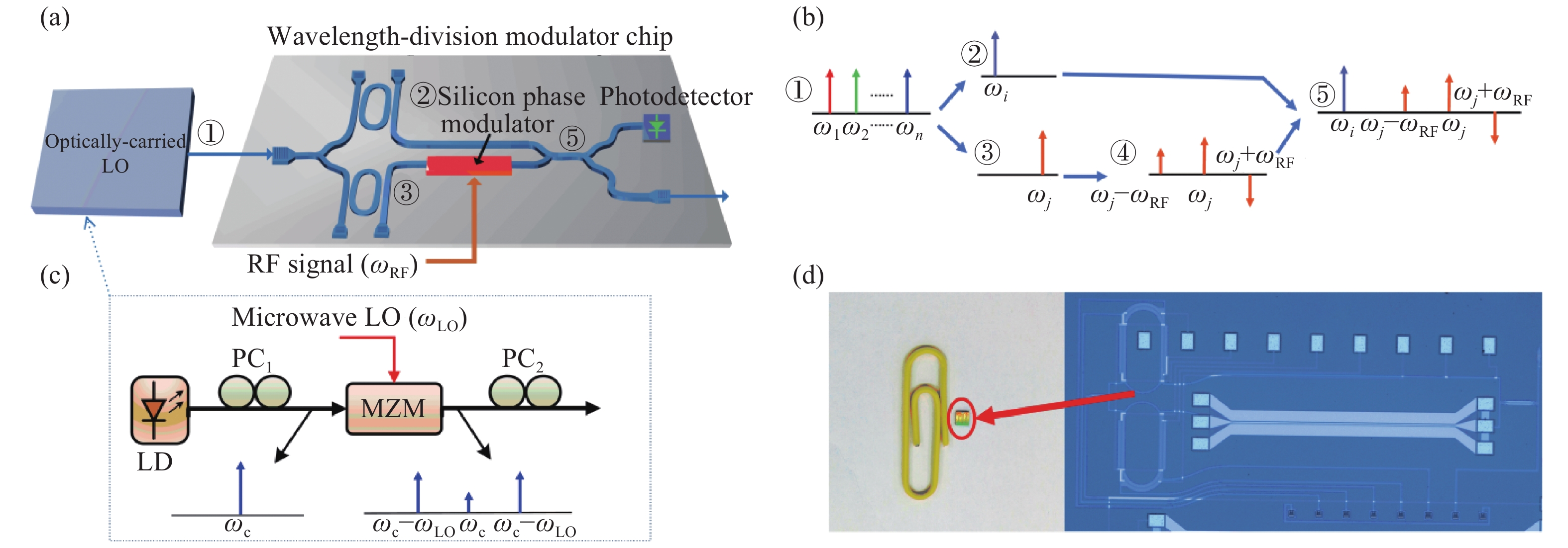
文中所研究的微波光子混频器原理框图如图1(a)所示。该微波光子混频器由光生本振单元和波长分离调制单元两部分组成。光生本振单元用于产生波长不同、幅度相同的本振光波。这些本振光波既可以是光域二倍频或高阶倍频的两个边带,也可以是光频梳中的多波长梳齿。波长分离调制单元通过两个光滤波器分别选取两个不同频率ω1和ω2的本振光波,即

图 1 (a) 文中所提微波光子混频器原理框图; (b) 系统中主要节点光信号示意图; (c) 文中实验采用的光生本振单元结构; (d) 波长分离调制芯片照片
Figure 1. (a) Schematic diagram of the proposed microwave photonic frequency mixer; (b) Optical signal at the main point of the system; (c) Optically-carried local oscillator used in the experiment; (d) Photographs of the wavelength-division modulator chip
$$\begin{array}{*{20}{l}} {{E_1}(t) = \exp ({\rm{j}}{\omega _1}t)}\\ {{E_2}(t) = \exp ({\rm{j}}{\omega _2}t)} \end{array} $$ (1) 两个本振光波在光电探测器中拍频产生频率为
${\omega _{{\rm{LO}}}}{\rm{ = }}\left| {{\omega _2}{\rm{ - }}{\omega _1}} \right|$ 的光生本振信号。其中一个本振光波(文中选取频率ω2的分量)通过片上相位调制器调制上频率为ωRF的RF信号。假设采用小信号调制,相位调制器输出的光信号可以表示为:$$ \begin{split} {E_{{\rm{PM - out}}}}(t) =& {{{{J}}_0}(\gamma )\exp ({\rm{j}}{\omega _2}t)} + {{{J}}_1}(\gamma )\cdot\exp [{\rm{j}}({\omega _2}t +{\omega _{{\rm{RF}}}}t +\\ & \pi /2)]{ - {{{J}}_1}(\gamma )\exp [{\rm{j}}({\omega _2}t - {\omega _{{\rm{RF}}}}t - \pi /2)]} \end{split} $$ (2) 式中:Ji(γ)为第i阶贝塞耳函数。该路光信号经光耦合器与另一路本振光波合路后送入光电探测器,此时光信号可以表示为:
$$ \begin{split} {E_{{\rm{PD - in}}}}(t) =& {\exp ({\rm{j}}{\omega _1}t){\rm{ + }}{{{J}}_0}(\gamma )\exp ({\rm{j}}{\omega _2}t)} + {{{J}}_1}(\gamma )\exp [{\rm{j}}({\omega _2}t + \\ & {\omega _{{\rm{RF}}}}t +\pi /2)]{ - {{{J}}_1}(\gamma )\exp [{\rm{j}}({\omega _2}t - {\omega _{{\rm{RF}}}}t - \pi /2)]} \end{split} $$ (3) 经光电探测器光电转换后的电流信号可以表示为:
$$ \begin{split} &s(t)\propto {E}_{\rm{PD-in}}(t)\cdot {E}_{\rm{PD-in}}^{*}(t)={{J}}_{0}(\gamma )\cos[({\omega }_{2}-{\omega }_{1})t]-{{J}}_{1}(\gamma )\cdot\\ &\sin[({\omega }_{2}-{\omega }_{1}+{\omega }_{\rm{RF}})t]-{{J}}_{1}(\gamma )\sin[({\omega }_{2}-{\omega }_{1}-{\omega }_{\rm{RF}})t+\\ &{{J}}_{1}^{2}(\gamma )\cos[2{\omega }_{\rm{RF}}t]={{J}}_{0}(\gamma )\cos({\omega }_{{\rm{LO}}{\text{光}}}t)-{\rm{J}}_{1}(\gamma )\sin[({\omega }_{{\rm{LO}}{\text{光}}}+\\ &{\omega }_{\rm{RF}})t]-{{J}}_{1}(\gamma )\sin[({\omega }_{{\rm{LO}}{\text{光}}}-{\omega }_{\rm{RF}})t+{{J}}_{1}^{2}(\gamma )\cos(2{\omega }_{\rm{RF}}t) \end{split} $$ (4) 从公式(4)可以看出,输出的电信号中包含了上变频信号ωLO光+ωRF和下变频信号ωLO光−ωRF。由于采用了相位调制,理论上不会存在RF分量ωRF。然而,拍频产生的电信号中还会存在光生本振分量ωLO和RF的2次谐波分量2ωRF。在小信号调制下,1阶贝塞耳函数远小于1。因此,RF的2次谐波分量2ωRF强度很弱,可以忽略。在实际系统中,由于光生本振的频率是已知的,可以通过电滤波器予以滤除。
-
笔者基于比利时微电子研究中心(Interuniversity Microelectronics Centre,IMEC)的iSIPP50G硅光工艺设计了波长分离调制芯片,并完成了流片制作。芯片照片如图1(a)所示,波导宽450 nm,高220 nm,整个芯片的尺寸大小为0.9 mm×2.5 mm。芯片上集成了硅基相位调制器、微环滤波器、光电探测器、多模干涉型光耦合器和光栅耦合器。用于选取本振光波的微环滤波器采用跑道型微环结构,微环腔长为996.6 μm,耦合区长度200 μm,波导和环腔之间的间隔为650 nm。在环腔上设有加热电极,用热光效应改变波导折射率,从而调谐微环的滤波波长。微环传输响应的测量结果如图2所示,其抑制比为20 dB,自由频谱范围为0.58 nm。

图 2 微环滤波器的传输响应
Figure 2. Transmission response of the micro-ring filter
基于该芯片进行了微波光子次谐波混频实验。在实验中,光生本振单元由可调激光器(Agilent N7714A)、偏振控制器、马赫增德尔调制器 (FUJITSU, FTM7928EZ)和微波源 (Keysight, N5235A)组成。可调激光器输出波长为1553.3 nm的光载波注入马赫增德尔调制器。调整马赫增德尔调制器的直流偏置使其工作在最小输出点,并将微波源输出的频率ωLO=19.5 GHz、功率8 dBm的电LO信号加载到马赫增德尔调制器上。输出马赫增德尔调制器的光信号是抑制载波双边带调制形式,光谱如图3(a)所示。由于采用±1阶边带(1553.17 nm和1553.48 nm)作为光生本振的分量,因此产生的光生微波本振频率是微波源直接输出的电LO频率的2倍,即39 GHz。

图 3 测量的光信号光谱。 (a) 输入芯片;(b) 输出芯片
Figure 3. Measured optical spectra of optical signal. (a) Coupled in the chip; (b) Coupled output from the chip
光生本振单元输出的±1阶本振光波经偏振控制器调整偏振态后通过阵列光纤耦合进波长分离调制芯片。在芯片中,光被1×2 光耦合器分为上下两路,每一路各级联一个微环滤波器。通过调节微环滤波器热调电极的驱动电压,改变微环的谐振波长,使上下两路微环滤波器分别选出一个本振光波。下路的微环滤波器与硅基相位调制器相连。用射频探针(MPI,T50A-GSG100)将RF信号源(RONDE & SCHWARZ,ZVA 67)输出的RF信号加载到硅基相位调制器上。相位调制器的输出端通过2×2光耦合器与另一路光信号合路后被分成2路,分别输入片上光电探测器和输出光栅耦合器。当调制的RF信号频率ωRF=14 GHz、功率14 dBm时,输出芯片的光信号光谱如图3(b)所示。从图中可以看出,仅有波长为1553.17 nm的−1阶本振光波两侧出现了边带,且边带与−1阶本振光波之间的波长差约为0.112 nm,对应频率间隔为14 GHz。结果表明,芯片上的2个微环滤波器能够分别选取±1阶本振光波,且硅基相位调制器可以正常工作。由于芯片插损较大、片上射频串扰严重,实验中将耦合出芯片的光信号经掺铒光纤放大器放大后,输入外置光电探测器 (KG-PD-50G)进行光电转换,用频谱仪观察输出频谱。
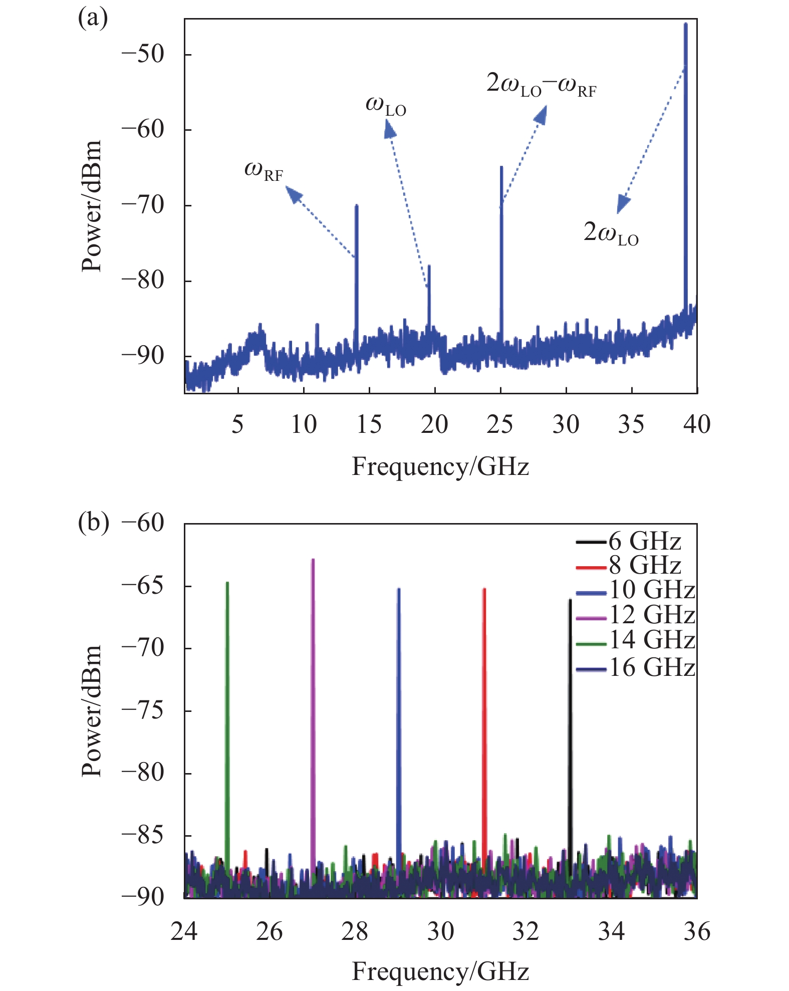
图4(a)是图3(b)对应光信号拍频得到的电频谱。从图中可以观察到以下频率分量:光生微波本振信号ωLO光=2ωLO=39 GHz,次谐波变频信号2ωLO−ωRF=25 GHz,电本振信号ωLO=19 GHz,RF信号ωRF=14 GHz。其中,次谐波变频分量2ωLO−ωRF是所希望得到的频谱分量;而另一个次谐波变频分量2ωLO+ωRF超出了频谱仪的量程,无法被观测;其他频率分量均为杂散分量。由于波长分离调制芯片采用了相位调制,RF杂散分量ωRF在理论上是不存在的。但实验结果显示,RF杂散分量ωRF的功率比目标混频分量2ωLO−ωRF的功率仅低了5 dB。这是因为微环滤波器的抑制比有限,导致原本应全部进入相位调制器所在支路的−1阶本振光波会泄露到另一支路上。泄露的−1阶本振光波在滤波和片上波导传播过程中引入了额外的相移。当泄露的−1阶本振光波与被调制的−1阶本振光波合路时,会改变−1阶本振光波的相位,使得相位调制不再理想,生成了RF杂散分量ωRF。笔者将在第3部分讨论如何抑制RF杂散分量。光生本振杂散分量2ωLO是两个本振光波拍频产生的,其频率是固定的,可使用电滤波器滤除。电本振杂散分量ωLO是±1阶光生本振与未完全抑制的光载波拍频产生的,其频率也是固定的,可以通过提高微环滤波器抑制比、使用额外的光滤波器或电滤波器等方法进行抑制,通常为了提高系统工作带宽,以光滤波的形式为佳。

图 4 测量的系统输出电频谱。(a) RF信号ωRF=14 GHz (大频率范围);(b) RF信号在6~16 GHz范围内调谐
Figure 4. Measured electrical spectra of system output. (a) ωRF=14 GHz (in a large frequency range); (b) RF frequency tuned in a frequency range from 6 to 16 GHz
图4(b)是当微波源输出频率保持为ωLO=19.5 GHz,在6~16 GHz范围内调谐RF信号源的输出频率,所得的拍频信号电频谱图。从图中可以看出,产生的次谐波变频信号2ωLO−ωRF的频率在33~23 GHz之间,功率波动小于5 dB。
-
根据前文分析可知,光滤波器引起的−1阶本振光波泄露会使得两路信号合波后−1阶本振光波相位发生变化,导致进入光电探测器的光信号不再是理想的相位调制。
利用Optisystem仿真软件搭建了文中所提的微波光子次谐波混频系统。其中,光生本振单元同样采用马赫增德尔调制器的载波抑制双边带调制形式。为了同时考虑滤波过程中,微环滤波器幅度和相位的响应对本振光波的影响,利用软件中的MATLAB组件实现自定义的微环滤波器传输响应。设定电LO微波源输出频率ωLO=16 GHz,RF信号源输出频率ωRF=5 GHz,则次谐波混频的目标频率为2ωLO−ωRF=27 GHz。
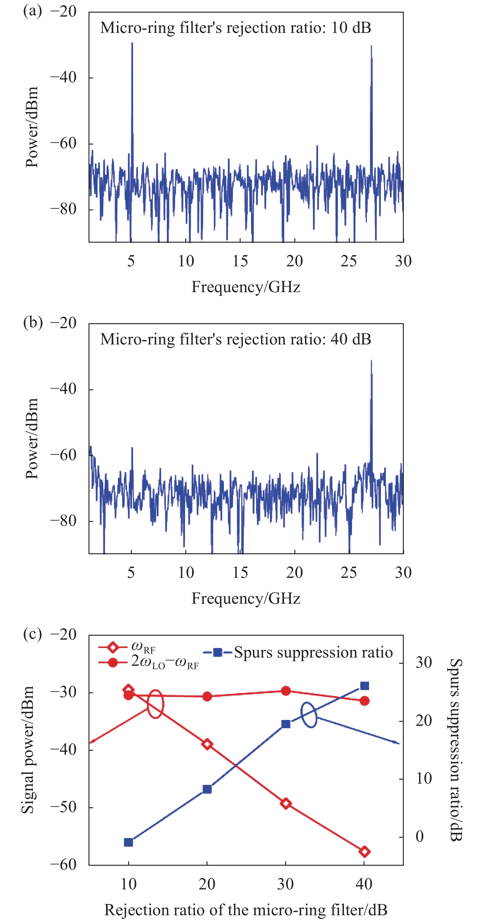
首先分析微环滤波器抑制比对RF杂散分量ωRF的影响。通过设定微环传输损耗、耦合系数等参数,改变微环滤波器的抑制比。图5(a)、(b)是微环滤波器抑制比分别为10 dB和40 dB时,RF杂散分量ωRF最大所对应的频谱图。从图中可以发现,微环滤波器抑制比为10 dB时,RF杂散分量ωRF很高,甚至大于了次谐波混频分量2ωLO−ωRF;而微环滤波器抑制比为40 dB时,RF杂散分量ωRF明显减小,与次谐波混频分量2ωLO-ωRF相差约26 dB。图5(c)给出了不同微环滤波器抑制比下,次谐波混频分量2ωLO−ωRF功率、RF杂散分量ωRF功率以及两者间的杂散抑制比。从图中可以看出,随着微环滤波器抑制比的增加,次谐波混频2ωLO−ωRF的功率基本不变,而RF杂散分量ωRF迅速下降,两者间杂散抑制比与微环滤波器抑制比成线性关系。因此,提高波长分离调制芯片上光滤波器的抑制比是抑制RF杂散分量ωRF的有效方法。与光子集成技术相适应的高抑制比光滤波器大多采用级联多个微环的方法,例如,中山大学报道了采用5个级联微环可以实现>60 dB的抑制比[15]。然而,级联多个微环会增加芯片面积,通常需要对每个微环进行精细调节,导致芯片的控制电路复杂,此外多个电极还容易在芯片上引入额外的热串扰。

图 5 仿真得到的频谱图。微环滤波器抑制比(a) 10 dB和(b) 40 dB;(c) 不同微环抑制比对应的次谐波混频2ωLO−ωRF功率、RF杂散分量ωRF功率和两者间杂散抑制比
Figure 5. Simulated frequency spectra when the rejection ratio of the micro-ring filter is (a) 10 dB and (b) 40 dB; (c) Power of 2ωLO−ωRF and ωRF, and the spurs suppression ratio for the different rejection ratio of the micro-ring filter
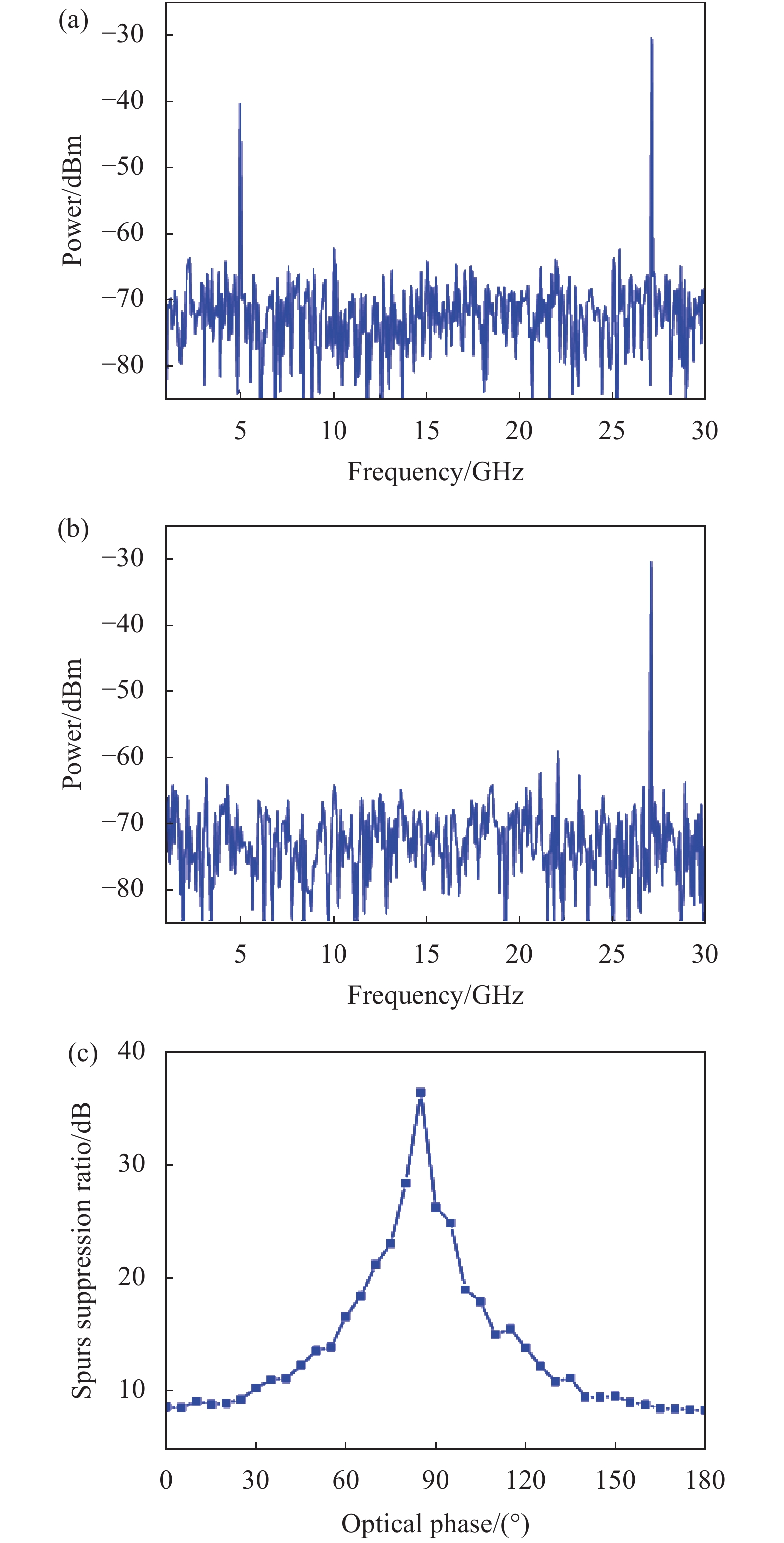
产生RF杂散分量ωRF的本质原因是泄露的−1阶本振光波与被相位调制的−1阶本振光波在合波过程中发生了相位变化,破坏了理想的相位调制。因此,可以在没有相位调制器的支路上设置光移相器。通过修正泄露的−1阶本振光波相位,使其与被相位调制的−1阶本振光波合波后,−1阶本振光波的相位不发生变化。此时,输入光电探测器的光信号仍然是理想的相位调制信号,则拍频不会产生RF杂散分量ωRF。为验证该想法,在微环滤波器抑制比为20 dB的仿真系统中加入光移相器,对移相角度进行扫描,并观察相应的频谱。仿真中,移相器相位变化步进为5°,扫描范围0°~180°。仿真结果如图6所示,通过光相移器改变泄露的−1阶本振光波相位,当光移相器的相位为85°时,RF杂散分量ωRF可以被抑制超过30 dB。采用这一方案,无需复杂的高抑制比光滤波器结构,也可以很好地抑制RF杂散分量ωRF,更适合于集成微波光子混频芯片。

图 6 仿真得到的频谱图。 (a) RF杂散分量ωRF最大;(b) RF杂散分量ωRF最小;(c) 杂散抑制比和光移相器相位的关系关系
Figure 6. Simulated frequency spectra with (a) the maximum mixing spurs ωRF and (b) the minimum mixing spurs ωRF; (c) The spurs suppression ratio vs. the phase value of the optical phase shifter
文中所提的微波光子混频方法由光生本振单元和波长分离调制单元两部分组成。文中介绍了波长分离调制单元芯片化的研究进展。光生本振单元同样也可以实现芯片化。在光域倍频方面,近几年与光子集成技术相兼容的SOI、硅基铌酸锂薄膜高速调制器被相继报道[16-17]。参考文献[12]在硅基芯片上级联了两个调制器,能够同时实现二倍频线性调频信号产生和光域混频去斜处理。在集成光频梳方面,瑞士洛桑联邦理工学院报道了重复频率已可低至10 GHz的微腔光频梳[18]。这些研究工作使光生本振芯片,甚至在同一芯片上集成光生本振单元和波长分离调制单元成为可能。
-
文中提出并研究了一种由光生本振单元和波长分离调制单元组成的微波光子混频器。设计并制作了基于SOI的波长分离调制芯片。该芯片集成了硅基相位调制器、微环滤波器等光子器件。基于该芯片搭建了微波光子次谐波混频实验系统,实验中将6~16 GHz 的RF信号变频到33~23 GHz。针对实验过程中残留的RF杂散分量,分析得出其产生原因在于:微环滤波器选取本振光波的过程中存在泄漏。提出了增加微环滤波器抑制比降低泄露光生本振幅度和引入光移相器修正泄漏光生本振相位两种解决方案,并通过仿真进行了验证。其中引入光移相器的方法更为简单,更适合于光子集成。
Chip-based microwave photonic frequency mixer (Invited)
-
摘要:
提出了一种由光生本振单元和波长分离调制单元组成的微波光子混频方法,并在绝缘体上硅材料上设计实现了上述波长分离调制芯片。该芯片集成了硅基相位调制器、微环滤波器、光电探测器、光耦合器和光栅耦合器。实验搭建了基于该波长分离调制芯片的微波光子次谐波混频系统,结果表明,该微波光子混频器可以将6~16 GHz的RF信号变频到33~23 GHz。此外,针对实验系统中残留的混频杂散,分别提出了增加微环滤波器抑制比降低泄露光生本振强度和引入光移相器修正泄漏光生本振相位两种解决方案。通过仿真验证可知,引入光移相器的方法更为简单,更适合于光子集成芯片。
Abstract:A microwave photonic frequency mixer constituted of an optically-carried local oscillator (LO) and a wavelength-division modulator was proposed. The wavelength-division modulator chip, which was consisted of a silicon phase modulator, two micro-ring filters, a photodetector, two optical couplers, and two grating couplers, was designed and fabricated. Based on the chip, a microwave photonic harmonic frequency mixer was implemented. In the experiment, an optically-carried LO was generated by double-sideband suppressed-carrier modulation at a Mach-Zehnder modulator. An RF signal from 6 to 16 GHz was successfully converted into a signal with a frequency of 33 to 23 GHz. In order to suppress the remaining mixing spurs, two solutions, i.e., increasing the rejection ratio of the micro-ring filter to decrease the intensity of the leaked optically-carried LO and introducing an optical phase shifter to correct the phase of the leaked optically-carried LO, were proposed and verified by simulation. It should be noted that the latter is simpler and more suitable for photonic integration.
-
图 1 (a) 文中所提微波光子混频器原理框图; (b) 系统中主要节点光信号示意图; (c) 文中实验采用的光生本振单元结构; (d) 波长分离调制芯片照片
Figure 1. (a) Schematic diagram of the proposed microwave photonic frequency mixer; (b) Optical signal at the main point of the system; (c) Optically-carried local oscillator used in the experiment; (d) Photographs of the wavelength-division modulator chip
图 3 测量的光信号光谱。 (a) 输入芯片;(b) 输出芯片
Figure 3. Measured optical spectra of optical signal. (a) Coupled in the chip; (b) Coupled output from the chip
图 4 测量的系统输出电频谱。(a) RF信号ωRF=14 GHz (大频率范围);(b) RF信号在6~16 GHz范围内调谐
Figure 4. Measured electrical spectra of system output. (a) ωRF=14 GHz (in a large frequency range); (b) RF frequency tuned in a frequency range from 6 to 16 GHz
图 5 仿真得到的频谱图。微环滤波器抑制比(a) 10 dB和(b) 40 dB;(c) 不同微环抑制比对应的次谐波混频2ωLO−ωRF功率、RF杂散分量ωRF功率和两者间杂散抑制比
Figure 5. Simulated frequency spectra when the rejection ratio of the micro-ring filter is (a) 10 dB and (b) 40 dB; (c) Power of 2ωLO−ωRF and ωRF, and the spurs suppression ratio for the different rejection ratio of the micro-ring filter
-
[1] Tang Z, Li Y, Yao J, et al. Photonics‐based microwave frequency mixing: methodology and applications [J]. Laser & Photonics Reviews, 2020, 14(1): 1800350. doi: 10.1002/lpor.201800350 [2] Tang Z, Pan S. Image-reject mixer with large suppression of mixing spurs based on a photonic microwave phase shifter [J]. Journal of Lightwave Technology, 2016, 34(20): 4729-4735. doi: 10.1109/JLT.2016.2550180 [3] Jiang T, Wu R, Yu S, et al. Microwave photonic phase-tunable mixer [J]. Optics Express, 2017, 25(4): 4519-4527. doi: 10.1364/OE.25.004519 [4] Zhao Y, Pang X, Deng L, et al. Ultra-broadband photonic harmonic mixer based on optical comb generation [J]. IEEE Photonics Technology Letters, 2011, 24(1): 16-18. doi: 10.1109/LPT.2011.2171939 [5] Pan S, Ye X, Zhang Y, et al. Microwave photonic array radars [J]. IEEE Journal of Microwaves, 2021, 1(1): 176-190. doi: 10.1109/JMW.2020.3034583 [6] Michael M E. Microwave photonics electronic warfare technologies for Australian defence[C]//2009 IEEE Avionics, Fiber-Optics and Photonics Technology Conference. IEEE, 2009: 1-2. [7] Duarte V C, Prata J G, Ribeiro C F, et al. Modular coherent photonic-aided payload receiver for communications satellites [J]. Nature Communications, 2019, 10(1): 1-9. doi: 10.1038/s41467-018-07882-8 [8] Burla M, Roeloffzen C G H, Zhuang L, et al. System integration and radiation pattern measurements of a phased array antenna employing an integrated photonic beamformer for radio astronomy applications [J]. Applied Optics, 2012, 51(7): 789-802. doi: 10.1364/AO.51.000789 [9] Zhu C, Lu L, Shan W, et al. Silicon integrated microwave photonic beamformer [J]. Optica, 2020, 7(9): 1162-1170. doi: 10.1364/OPTICA.391521 [10] Zhang W, Yao J. Silicon photonic integrated optoelectronic oscillator for frequency-tunable microwave generation [J]. Journal of Lightwave Technology, 2018, 36(19): 4655-4663. doi: 10.1109/JLT.2018.2829823 [11] Tang J, Hao T, Li W, et al. Integrated optoelectronic oscillator [J]. Optics Express, 2018, 26(9): 12257-12265. doi: 10.1364/OE.26.012257 [12] Li S, Cui Z, Ye X, et al. Chip‐based microwave‐photonic radar for high‐resolution imaging [J]. Laser & Photonics Reviews, 2020, 14(10): 1900239. doi: https://doi.org/10.1002/lpor.201900239 [13] Jin S, Xu L, Rosborough V, et al. RF frequency mixer photonic integrated circuit [J]. IEEE Photonics Technology Letters, 2016, 28(16): 1771-1773. doi: 10.1109/LPT.2016.2570520 [14] Bottenfield C G, Thomas V A, Saha G, et al. A silicon microwave photonic down-converter[C]//45th European Conference on Optical Communication (ECOC 2019). IET, 2019: 1-4. [15] Ge R, Cai X. High-extinction-ratio optical filters based on high-order silicon microring resonators[C]//2018 Conference on Lasers and Electro-Optics Pacific Rim (CLEO-PR). IEEE, 2018: 1-2. [16] Zhalehpour S, Lin J, Guo M, et al. All-silicon IQ modulator for 100 GBaud 32QAM transmissions[C]//Optical Fiber Communication Conference. Optical Society of America, 2019: Th4A. 5. [17] Xu M, He M, Zhang H, et al. High-performance coherent optical modulators based on thin-film lithium niobate platform [J]. Nature Communications, 2020, 11(1): 1-7. doi: 10.1038/s41467-019-13993-7 [18] Liu J, Lucas E, Raja A S, et al. Photonic microwave generation in the X-and K-band using integrated soliton microcombs [J]. Nature Photonics, 2020, 14: 486-491. doi: 10.1038/s41566-020-0617-x -

 点击查看大图
计量
- 文章访问数: 836
- HTML全文浏览量: 239
- 被引次数: 0


