


-
机动成像是减小遥感卫星重访周期,进行应急观测的主要成像模式。卫星机动成像会引起大气传输路径、分辨率等发生变化[1-2],不仅导致大气对比度变化,对于TDI 推扫式遥感器,还会引起不同视场的积分时间差异,从而引起在轨调制传递函数(MTF)的变化[3],下面主要从分辨率和辐亮度两个方面分析机动模式对TDI推扫相机的成像质量影响。
TDI(Time Delay Integration)推扫成像是目前中低轨高分辨率光学遥感器的主要成像方式,主要以模拟或数字信号的累计方式进行时间延迟积分,提高了图像传感器的SNR(Signal Noise Ratio)和灵敏度。TDI推扫成像要求不同级的同一像元对同一目标成像,才能保证最终的成像质量,因此对积分时间同步性提出了严格的要求。理想的积分时间是地物在焦面成的像移动一行(级)TDICCD所需要的时间,当满足理想积分时间条件时,像的移动速度和TDICCD电荷转移速度相同,没有像移;否则会导致像移,系统MTF下降。
-
分辨率计算采用各视场点视轴追迹方法,分析各矢量沿着不同视场的视轴在地面的投影矢量。首先根据卫星星下点成像的坐标系和侧摆坐标系之间的关系构建坐标系转换矩阵,建立不同视场的视轴矢量随侧摆或俯仰角度的变化函数,然后根据沿轨和垂轨方向的像方矢量分别得到在地面投影的矢量,根据以上矢量得到地面像元分辨率,同时计算卫星飞行速度在地面像元的投影速率,从而分析出不同视场的积分时间随侧摆角度变化的函数。此外,还通过影像坐标转换关系对视轴追迹方法进行了验证[6-9]。
分辨率计算具体实现步骤如下:
(1) 设定参数
P:像元尺寸;f:相机焦距;h:轨道高度;R:地球半径;
θ:侧摆角度;φ:俯仰角度
(2) 设定星下点坐标系C1
+X:卫星飞行方向 [1 0 0];+ Z :卫星指向星下点 [0 0 1];+ Y :线阵方向,根据 X 和 Z 右手螺旋定则规定 [0 1 0]
(3) 根据相机不同视场角计算观测视轴在相机本体坐标系中单位矢量
$ {r_{sz}} $ :$$ {r_{sz}} = [\tan ({\theta _x}) \;\;\;{\tan ({\theta _y})}\;\;\;1 ]/\left| {\tan ({\theta _x}) \;\;\;{\tan ({\theta _y})}\;\;\;1 } \right| $$ (1) 式中:
$ {\theta _x} $ 表示X方向的视场角;$ {\theta _y} $ 表示Y方向的视场角;||表示取模(后同),表示对矢量进行归一化。(4) 计算卫星侧摆或俯仰后,相机视轴、沿轨(X方向)和垂轨(Y方向)的单位矢量在星下点坐标系中的矢量,假定相机先绕滚动轴旋转
$ \theta $ 、再绕俯仰轴旋转$ \phi $ 。视轴方向单位矢量rsz为:
$$ \begin{split} &r_{sz} = \dfrac{\left[{\rm tan}\left(fovx\right)\;\begin{array}{ccc} & {\rm tan}(fovy) & 1\end{array}\right]}{\left|{\rm tan}(fovx)\begin{array}{ccc} & {\rm tan}(fovy) & 1\end{array}\right|}\times \left[\begin{array}{ccc}1 & 0 & 0\\ 0 & {\rm cos}\theta & -{\rm sin}\theta \\ 0 & {\rm sin}\theta & {\rm cos}\theta \end{array}\right]\times \left[\begin{array}{ccc}{\rm cos}\varphi & 0 & -{\rm sin}\varphi \\ 0 & 1 & 0\\ {\rm sin}\varphi & 0 & {\rm cos}\varphi \end{array}\right] =\\ &\dfrac{\left[\begin{array}{c}{\rm tan}(fovx)\;{\rm cos}\varphi -{\rm tan}(fovy)\;{\rm sin}\theta\; {\rm sin}\varphi +{\rm cos}\theta \; {\rm sin}\varphi \; \mathit{\rm tan}(fovy)\; \mathit{\rm cos}\theta +\mathit{\rm sin}\theta \\ -\mathit{\rm tan}(fovx)\;\mathit{\rm sin}\varphi -\mathit{\rm tan}(fovy)\;\mathit{\rm sin}\theta \;\mathit{\rm\rm cos}\varphi +\mathit{\rm cos}\theta \; \mathit{\rm cos}\varphi \end{array}\right]}{\left|\mathit{\rm tan}(fovx)\begin{array}{ccc}& \mathit{\rm tan}(fovy)& 1\end{array}\right|} \end{split} $$ (2) 沿轨方向单位矢量
$ {r_{yg}} $ 为:$$ \begin{split} {r_{yg}} = \left[ {1\begin{array}{*{20}{c}} {}&0&0 \end{array}} \right] \times \left[ {\begin{array}{*{20}{c}} 1&0&0 \\ 0&{\cos \theta }&{ - \sin \theta } \\ 0&{\sin \theta }&{\cos \theta } \end{array}} \right] \times \\ \left[ {\begin{array}{*{20}{c}} {\cos \phi }&0&{ - \sin \phi } \\ 0&1&0 \\ {\sin \phi }&0&{\cos \phi } \end{array}} \right] = \left[\cos \begin{array}{*{20}{c}} \phi &0&{ - \sin \phi } \end{array}\right] \end{split} $$ (3) 垂轨方向单位矢量
$ {r_{cg}} $ 为:$$ \begin{split} &{r_{cg}} = \left[ {0\begin{array}{*{20}{c}} {}&1&0 \end{array}} \right] \times \left[ {\begin{array}{*{20}{c}} 1&0&0 \\ 0&{\cos \theta }&{ - \sin \theta } \\ 0&{\sin \theta }&{\cos \theta } \end{array}} \right] \times \\ &\left[ {\begin{array}{*{20}{c}} {\cos \phi }&0&{ - \sin \phi } \\ 0&1&0 \\ {\sin \phi }&0&{\cos \phi } \end{array}} \right] = \left[ - \sin \theta \sin \phi \begin{array}{*{20}{c}} &{\cos \theta }&{ - \sin \theta \cos \phi } \end{array} \right] \end{split} $$ (4) (4) 计算机动后,视轴到地面之间的距离
视轴与Z轴之间的夹角
$\delta $ 为:$$ \delta = \arccos \left(\frac{{ - \tan (\theta {}_x)\sin \phi - \tan (\theta {}_y)\sin \theta \cos \phi + \cos \theta \cos \phi }}{{\left| {\tan (\theta {}_x) \;\;\;{\tan (\theta {}_y)}\;\;\;1 } \right|}}\right) $$ (5) 则中心到地面的距离:
$$ L = \cos (\delta ) \times (R + h) - \frac{{\sqrt {4{{(\cos (\delta ))}^2} \times {{(R + h)}^2} - 4{h^2} - 8Rh} }}{2} $$ (6) (5) 计算机动后,沿轨和垂轨两个方向单位矢量在地面的投影矢量
${{r_{ygty}}}$ 和${{r_{cgty}}}$ 首先引入地面点的法向矢量
$ {r_{fx}} $ 为:$$ {r_{fx}} = {\text{ }}\left( {{{R}} + h} \right) \times \left[ {0{\text{ }}0{\text{ 1}}} \right] - {{L}} \times {{s_{zsl}}} $$ (7) 沿轨方向在地面的投影矢量
${{r}}_{{{ygty}}}={{r}}_{{{sz}}} \times {{k_1}}$ (${{k}}_1$ 为视轴方向上的部分沿轨矢量系数),垂轨方向在地面的投影矢量${{r}}_{{cgty}}={r}_{{cg}}+{r}_{{sz}} \times {k} _2$ (${{k}}_{{2}}$ 为视轴方向上的部分垂轨矢量系数),根据地面法向矢量与地面任意矢量垂直的法则,得到:$$ {\text{(}}{r_{yg}} + {r_{sz}} \times {{k1)}} * {r_{fx}} = {\text{ }}0 $$ $$ {\text{(}}{r_{cg}} + r{}_{sz} \times {{k2)}} * r{}_{fx}^{} = {\text{ }}0 $$ (8) 得到:
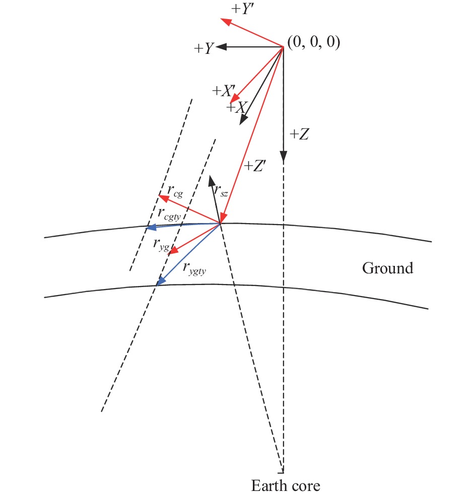
$$ {{k1}} = - \frac{{{r_{yg}} * r{}_{fx}\rm{'}}}{{{r_{sz}}*{r_{fx}}'}} $$ $$ {{k2}} = - \frac{{r{}_{cg} * {r_{fx}}'}}{{{r_{sz}}*{r_{fx}}'}} $$ (9) 矢量示意图如图1所示。

图 1 矢量示意图
Figure 1. Vector diagram
(6) 计算沿轨和垂轨两个方向的分辨率
$ S{}_{yg} $ 和$ S{}_{cg} $ $$ S{}_{yg} = \frac{{{{L}} \times {{p}}}}{{{f}}} \times \left| {{r_{ygty}}} \right| $$ (10) $$ {S_{cg}} = \frac{{{{L}} \times {{p}}}}{{{f}}} \times \left| {{r_{cgty}}} \right| $$ (11) (7) 计算卫星飞行速度在地面的投影速度分量
根据万有引力定律和向心力运动定律,得到:
$$ {V}_{ty}=\sqrt{\frac{G\times M\times R}{(R+h)^{3}}} $$ (12) 式中:G为外有引力常数;M为地球质量;R为地球半径,与经纬度有关;h为轨道高度,与经纬度有关。
(8)根据不同视场角度分别计算得到两个方向的GSD,然后以中心视场为积分时间设置基准,其余视场由于积分时间不同步造成的MTF下降情况。
$$ {MTF}\left(f\right)=\frac{\mathit{\rm sin} (f\times \Delta d\times pi\times N)}{N\times \mathit{\rm sin} (f\times \Delta d\times pi)} \Delta {d=}\left|\frac{S 1\times V2}{S 2\times V1}-1\right| $$ (13) 式中:
$\Delta {{d}}$ 为单级积分时间内的不同步率; S1为当前视场的分辨率; S2为基准视场的分辨率; V1为当前视场地面投影速度; V2为基准视场地面投影速度。 -
机动成像时辐亮度影响主要体现在大气对比度变化和镜面反射两方面,大气对比度会引起图像MTF的变化,主要表现在地面景物目标经过大气后到达相机入瞳处的对比度发生变化[10-13]。地面景物的对比度定义为:
$$ {C}_{\text{1}}=\frac{{\rho }_{目标}-{\rho }_{背景}}{{\rho }_{目标}+{\rho }_{背景}} $$ (14) 式中:
$ {\rho }_{目标} $ 和$ {\rho }_{背景} $ 分别为地面目标和背景的反射率。地面景物经过大气到达相机入瞳处的辐亮度对比度定义为:
$$ {C}_{\text{2}}=\frac{{L}_{目标}-{L}_{背景}}{{L}_{目标}+{L}_{背景}} $$ (15) 式中:
$ {L}_{目标} $ 和$ {L}_{背景} $ 分别为地面目标和背景到达相机入瞳处的辐亮度。用大气传递函数来表示地面景物经过大气后到达相机入瞳处的对比度变化因子,即:
$$ K = \frac{{{C_2}}}{{{C_1}}} $$ (16) 同时在机动成像过程中,还要考虑不同角度的镜面反射现象,即对表面比较光亮的物体成像,某些角度可能会形成镜面反射(类似逆光成像)。某卫星在多角度成像时,对同一条河流成像过程中,前俯仰、星下点和后俯仰成像时输出亮度的差别较大[14-16]。
-
根据2.1节分析过程对某九谱段相机载荷的在轨分辨率和MTF进行分析。相机输入参数如表1所示。
表 1 相机参数
Table 1. Camera parameters
Parameters name Result Camera focus/mm 1120 Pixel size B1-B8:28
P:7Orbit height/km 782 Roll angle/(°) [−30,30] Pitch angle/(°) [−25,+25] 首先根据探测器在焦面上的布局分别得到9个谱段中心和边缘在相机视场中的位置,如表2所示。
相机九谱段之间的成像示意如图2所示。
表 2 不同谱段相机视场
Table 2. Camera field of different bands
Band Field/(°) 0 +2.24 −2.24 B1 (+123.65,0) (+123.65,+43.8) (+123.65,−43.8) B4 (+129.78,0) (+129.78,+43.8) (+129.78,−43.8) B6 (+133.56,0) (+133.56,+43.8) (+133.56,−43.8) B8 (+137.31,0) (+137.31,+43.8) (+137.31,−43.8) B2 (+123.65,0) (+123.65,+43.8) (+123.65,−43.8) B3 (+127.77,0) (+127.77,+43.8) (+127.77,−43.8) B5 (+131.55,0) (+131.55,+43.8) (+131.55,−43.8) B7 (+134.65,0) (+134.65,+43.8) (+134.65,−43.8) P (+137.76,0) (+137.76,+43.8) (+137.76,−43.8) 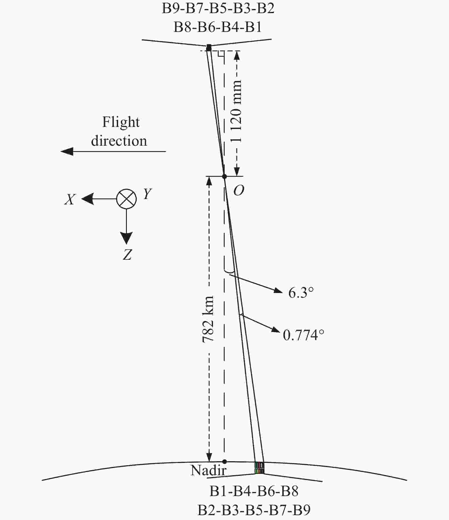
图 2 九谱段成像示意图
Figure 2. Imaging diagram of nine bands
根据2.1节的方法,计算各视场点在TDI方向和线阵方向的分辨率,由于TDI方向的分辨率变化会导致积分时间不同步,引起MTF下降,所以这里只给出TDI方向的分辨率,如表3、表4所示(表3、表4只给出了最靠近中心视场的B1谱段和距离中心视场最远的P谱段的分辨率,并且由于正负侧摆呈对称关系,所以只给出了一个方向侧摆的结果)。
表 3 相机B1谱段不同视场分辨率
Table 3. GSD of different fields in B1 spectrum band
Roll angle/(°) GSD of B1@0 field/m Pitch angle/(°) −20 −15 −10 −5 0 5 10 15 20 0 20.83 19.98 19.53 19.45 19.72 20.37 21.45 23.06 25.38 10 21.2 20.33 19.87 19.78 20.06 20.73 21.84 23.49 25.87 20 22.39 21.45 20.96 20.87 21.17 21.88 23.08 24.87 27.46 30 24.69 23.61 23.04 22.94 23.28 24.1 25.49 27.58 30.62 Roll angle/(°) GSD of B1@+2.24° field/m Pitch angle/(°) −20 −15 −10 −5 0 5 10 15 20 0 20.85 20 19.55 19.46 19.73 20.38 21.47 23.09 25.4 10 21.41 20.52 20.05 19.96 20.24 20.92 22.05 23.75 26.19 20 22.84 21.85 21.33 21.23 21.54 22.28 23.54 25.43 28.16 30 25.51 24.33 23.7 23.58 23.94 24.83 26.32 28.59 31.93 Roll angle/(°) GSD of B1@−2.24° field/m Pitch angle/(°) −20 −15 −10 −5 0 5 10 15 20 0 20.85 20 19.55 19.46 19.73 20.38 21.47 23.09 25.4 10 21.03 20.18 19.73 19.65 19.92 20.58 21.67 23.29 25.61 20 22 21.11 20.64 20.55 20.84 21.53 22.68 24.4 26.86 30 23.98 22.99 22.46 22.37 22.69 23.47 24.76 26.69 29.49 表 4 相机 P谱段不同视场分辨率
Table 4. GSD of different fields in P spectrum band
Roll angle/(°) GSD of P@0 field/m Pitch angle/(°) −20 −15 −10 −5 0 5 10 15 20 0 5.16 4.97 4.87 4.86 4.94 5.12 5.4 5.83 6.44 10 5.25 5.05 4.95 4.94 5.03 5.21 5.5 5.94 6.56 20 5.55 5.33 5.22 5.21 5.3 5.5 5.82 6.29 6.97 30 6.12 5.87 5.74 5.73 5.83 6.06 6.43 6.98 7.78 Roll angle/(°) GSD of P@+2.24 field/m Pitch angle/(°) −20 −15 −20 −5 −20 5 −20 15 −20 0 5.17 4.97 4.87 4.86 4.94 5.12 5.41 5.83 6.44 10 5.31 5.1 5 4.99 5.07 5.25 5.56 6 6.64 20 5.66 5.43 5.31 5.3 5.4 5.6 5.93 6.43 7.15 30 6.32 6.04 5.91 5.89 6 6.24 6.64 7.24 8.12 Roll angle/(°) GSD of P@−2.24 field/m Pitch angle/(°) −20 −15 −20 −5 −20 5 −20 15 −20 0 5.17 4.97 4.87 4.86 4.94 5.12 5.41 5.83 6.44 10 5.21 5.02 4.92 4.91 4.99 5.17 5.46 5.88 6.49 20 5.45 5.25 5.14 5.14 5.22 5.41 5.71 6.17 6.81 30 5.94 5.71 5.6 5.59 5.69 5.9 6.24 6.75 7.48 从表3和表4可以看出:机动成像后,边缘视场与中心视场分辨率发生了变化,导致整个视场范围内的理想积分时间不同。在轨一般以全色P谱段中心视场积分时间为基准,这种情况下会引起其他谱段积分时间的不同步,且距离P谱段越远,不同步率越高。下面给出距离P谱段最远的B1谱段在不同TDI级数下,各视场由于积分时间不同步影响的MTF。
从表5和表6可以看出,如果以P谱段为积分时间计算基准, B1谱段在选择TDI级数为60级时,边缘视场的奈频处MTF在大俯仰角度下奈频处MTF已退化到0,因此在选择侧摆成像时需要降低TDI级数使用。
表 5 相机B1谱段不同视场MTF
Table 5. MTF of different fields in B1 spectrum band
Roll angle/(°) MTF of 0° field(TDI stage=60) Pitch angle/(°) −20 −15 −10 −5 0 5 10 15 20 0 0.894 0.950 0.985 1.000 0.994 0.968 0.918 0.841 0.730 10 0.893 0.950 0.985 1.000 0.994 0.967 0.916 0.838 0.725 20 0.889 0.949 0.985 1.000 0.993 0.965 0.912 0.829 0.710 30 0.881 0.945 0.984 1.000 0.992 0.961 0.902 0.809 0.674 Roll angle/(°) MTF of +2.24° field(TDI stage=60) Pitch angle/(°) −20 −15 −10 −5 0 5 10 15 20 0 0.869 0.934 0.976 0.997 0.998 0.978 0.936 0.867 0.766 10 0.556 0.692 0.799 0.878 0.935 0.972 0.993 1.000 0.993 20 0.141 0.314 0.466 0.589 0.685 0.754 0.803 0.835 0.851 30 0 0 0.041 0.161 0.255 0.314 0.333 0.310 0.238 Roll angle/(°) MTF of −2.24° field(TDI stage=60) Pitch angle/(°) −20 −15 −10 −5 0 5 10 15 20 0 0.869 0.934 0.976 0.997 0.998 0.978 0.936 0.867 0.766 10 0.999 0.997 0.980 0.944 0.886 0.802 0.685 0.532 0.340 20 0.892 0.853 0.797 0.718 0.611 0.473 0.303 0.109 0 30 0.510 0.484 0.424 0.332 0.208 0.060 0 0 0 表 6 相机P谱段不同视场MTF
Table 6. MTF of different fields in P spectrum band
Roll angle/(°) MTF of 0° field(TDI stage=60) Pitch angle/(°) −20 −15 −20 −5 −20 5 −20 15 −20 0 1 1 1 1 1 1 1 1 1 10 1 1 1 1 1 1 1 1 1 20 1 1 1 1 1 1 1 1 1 30 1 1 1 1 1 1 1 1 1 Roll angle/(°) MTF of +2.24° field(TDI stage=60) Pitch angle/(°) −20 −15 −20 −5 −20 5 −20 15 −20 0 1.000 1.000 1.000 1.000 1.000 1.000 1.000 1.000 1.000 10 0.977 0.980 0.982 0.983 0.982 0.980 0.977 0.972 0.964 20 0.909 0.922 0.929 0.931 0.929 0.921 0.908 0.885 0.850 30 0.766 0.800 0.819 0.825 0.818 0.798 0.761 0.700 0.606 Roll angle/(°) MTF of −2.24° field(TDI stage=60) Pitch angle/(°) −20 −15 −20 −5 −20 5 −20 15 −20 0 1.000 1.000 1.000 1.000 1.000 1.000 1.000 1.000 1.000 10 0.986 0.988 0.989 0.989 0.989 0.988 0.985 0.982 0.976 20 0.932 0.941 0.946 0.948 0.946 0.940 0.930 0.913 0.887 30 0.820 0.844 0.858 0.862 0.857 0.841 0.813 0.768 0.699 -
以目标反射率为0.1,背景反射率为0.2为例(亮背景下的暗目标),计算侧摆对图像背景调制度的影响,如表7所示。
从表7可以看出:在卫星侧摆成像时,其大气程辐射增加,邻近像元辐亮度也增加,即在侧摆时大气对成像质量的影响程度增加;从调制度计算结果可以看出,在侧摆成像时,目标调制度减小,即在侧摆时相机获得的原始图像的对比度会下降。
表 7 不同侧摆角下目标与背景辐亮度变化
Table 7. Radiance variation between target and background with different roll angles
Radiance name Roll angle=0° Roll angle=30° Background Aero radiance/W·m−2·sr−1 12.521 19.328 Adjacent pixel radiance/W·m−2·sr−1 7.868 8.942 Total radiance/W·m−2·sr−1 59.045 64.521 Target Aero radiance/W·m−2·sr−1 12.521 19.328 Adjacent pixel radiance/W·m−2·sr−1 7.856 8.932 Total radiance/W·m−2·sr−1 39.704 46.385 Modulation 0.196 0.164 注:表中,图像背景调制度=(目标总辐亮度−目标大气程辐亮度−目标邻近像元辐亮度)/(背景总辐亮度+目标总辐亮度) -
某型号对水面成像时,同一区域输出DN值差异较大,正向俯仰输出DN达到400多(10 bit量化),而无俯仰和反向俯仰小于100 DN。成像条件如表8所示。
表 8 相机不同成像模式的观测角度(单位:(°))
Table 8. Pitch and side angles with different imaging modes(Unit: (°))
View mode Side angle Pitch angle Sun elevation Sun azimuth Satellite zenith Satellite azimuth Forward pitch 13.39 30.39 62.75 162 32.95 −13.52 No pitch 13.16 0.27 62.8 162.85 13.16 98.00 Backwark pitch 13.40 −30.01 62.9 163.3 32.61 29.83 注:正向俯仰指相机视轴在XOZ平面投影在第一象限,即卫星降交点成像时向南俯仰;反向俯仰指相机视轴在XOZ平面投影在第二象限,即卫星降交点成像时向北俯仰;无俯仰指俯仰角度小于1° 上表中的侧摆角、俯仰角、太阳高度角和太阳方位角是从卫星下传辅助数据中得到的,卫星天顶角和方位角是根据侧摆和俯仰角度计算的。从表格中的数据可以看出:正向俯仰时,卫星在目标的西北边,而太阳恰好在目标的东南边,卫星的天顶角和太阳天顶角接近,方位角近似在一条直线上,且水面又属于镜面目标,以上条件导致成像接近镜面反射时,此时水面目标的反射能量大于漫反射成像时的能量,因此输出DN值偏高。而反向俯仰和无俯仰不满足镜面反射的条件,水面按照漫反射目标成像。
-
文中主要从分辨率和辐亮度两个方面对侧摆成像模式下的成像质量进行了分析,分析结果表明:侧摆模式会导致不同试场的分辨率不一致,侧摆角度越大,不一致性越明显,进而导致不同试场的理想积分时间不一致,如果统一采用中心试场积分时间,会影响边缘的不一致性。文中以某九谱段相机载荷为例分析了不同谱段在不同侧摆角度下由于积分时间误差导致的边缘试场MTF下降情况,为在轨参数调整提供了理论依据。
同时,文中还对不同侧摆条件下的图像对比度以及多角度成像时图像亮度进行了分析,为后期的图像校正和成像质量分析提供了理论参考。
Maneuvering imaging quality of space TDI push scan optical remote sensor
-
摘要: 从分辨率和辐亮度两个角度出发,对TDI推扫相机机动成像模式下的成像质量进行了分析。首先,提出了视轴追迹法分析计算TDI和线阵两个方向的分辨率,通过构建侧摆和星下点之间的坐标转换矩阵,得到不同机动角度下TDI和线阵方向的单位矢量,随后计算出这两个方向的单位矢量沿着视轴方向在地面的投影矢量,结合相机的参数和轨道高度、地球半径等计算出地面像元分辨率。同时根据卫星在地面的投影速率得到不同视场的积分时间,并分析以中心视场为积分时间基准下,边缘视场在不同TDI级数下的MTF退化情况。以某遥感型号为例进行了具体的分析计算,并根据MTF的退化情况对侧摆角度提出了要求,计算结果表明,边缘谱段在大侧摆下TDI级数为60时,MTF已下降为0,在轨使用时要慎重选用级数。然后,结合理论计算和在轨图像分析了了不同侧摆角度下大气对图像对比度的影响,通过分析表明侧摆会改变大气传输路径,从而影响目标的对比度,分析结果可以为后期的图像校正提供参考。Abstract: The imaging quality of TDI push broom camera in maneuvering imaging mode is analyzed from the perspectives of resolution and radiance. Firstly, the Los tracking method is proposed to analyze and calculate the resolution of TDI and linear array directions. By constructing the coordinate conversion matrix between sidesway and satellite points, the unit vectors of TDI and linear array in different maneuver angles are obtained. Then, the projection vectors of the unit vectors in two directions on the ground are calculated along the Los direction, the ground pixel resolution is calculated, combined with the parameters of the camera, the orbital height and the earth radius. At the same time, the integration time of different fields of view are obtained according to the projection rate of the satellite on the ground, and the MTF degradation of edge fields of view under different TDI stages is analyzed with the reference integration time of central field of view. Taking a remote sensing model as an example, the specific analysis and calculation are carried out, and the requirements for the yaw angle are put forward according to the degradation of MTF. The calculated results show that the MTF of the edge spectrum section has decreased to 0 when the TDI series is 60 under the large side sway, so the TDI stage should be selected carefully in orbit. Then, combined with the theoretical calculation and on orbit image, the influence of the atmosphere on the image contrast under different side or yaw angles is analyzed. The analysis shows that the yaw will change the atmospheric transmission path, thus affecting the target contrast. The analysis results can provide a reference for the later image correction.
-
表 1 相机参数
Table 1. Camera parameters
Parameters name Result Camera focus/mm 1120 Pixel size B1-B8:28
P:7Orbit height/km 782 Roll angle/(°) [−30,30] Pitch angle/(°) [−25,+25]  下载: 导出CSV
表 2 不同谱段相机视场
Table 2. Camera field of different bands
Band Field/(°) 0 +2.24 −2.24 B1 (+123.65,0) (+123.65,+43.8) (+123.65,−43.8) B4 (+129.78,0) (+129.78,+43.8) (+129.78,−43.8) B6 (+133.56,0) (+133.56,+43.8) (+133.56,−43.8) B8 (+137.31,0) (+137.31,+43.8) (+137.31,−43.8) B2 (+123.65,0) (+123.65,+43.8) (+123.65,−43.8) B3 (+127.77,0) (+127.77,+43.8) (+127.77,−43.8) B5 (+131.55,0) (+131.55,+43.8) (+131.55,−43.8) B7 (+134.65,0) (+134.65,+43.8) (+134.65,−43.8) P (+137.76,0) (+137.76,+43.8) (+137.76,−43.8)
下载: 导出CSV
表 3 相机B1谱段不同视场分辨率
Table 3. GSD of different fields in B1 spectrum band
Roll angle/(°) GSD of B1@0 field/m Pitch angle/(°) −20 −15 −10 −5 0 5 10 15 20 0 20.83 19.98 19.53 19.45 19.72 20.37 21.45 23.06 25.38 10 21.2 20.33 19.87 19.78 20.06 20.73 21.84 23.49 25.87 20 22.39 21.45 20.96 20.87 21.17 21.88 23.08 24.87 27.46 30 24.69 23.61 23.04 22.94 23.28 24.1 25.49 27.58 30.62 Roll angle/(°) GSD of B1@+2.24° field/m Pitch angle/(°) −20 −15 −10 −5 0 5 10 15 20 0 20.85 20 19.55 19.46 19.73 20.38 21.47 23.09 25.4 10 21.41 20.52 20.05 19.96 20.24 20.92 22.05 23.75 26.19 20 22.84 21.85 21.33 21.23 21.54 22.28 23.54 25.43 28.16 30 25.51 24.33 23.7 23.58 23.94 24.83 26.32 28.59 31.93 Roll angle/(°) GSD of B1@−2.24° field/m Pitch angle/(°) −20 −15 −10 −5 0 5 10 15 20 0 20.85 20 19.55 19.46 19.73 20.38 21.47 23.09 25.4 10 21.03 20.18 19.73 19.65 19.92 20.58 21.67 23.29 25.61 20 22 21.11 20.64 20.55 20.84 21.53 22.68 24.4 26.86 30 23.98 22.99 22.46 22.37 22.69 23.47 24.76 26.69 29.49
下载: 导出CSV
表 4 相机 P谱段不同视场分辨率
Table 4. GSD of different fields in P spectrum band
Roll angle/(°) GSD of P@0 field/m Pitch angle/(°) −20 −15 −10 −5 0 5 10 15 20 0 5.16 4.97 4.87 4.86 4.94 5.12 5.4 5.83 6.44 10 5.25 5.05 4.95 4.94 5.03 5.21 5.5 5.94 6.56 20 5.55 5.33 5.22 5.21 5.3 5.5 5.82 6.29 6.97 30 6.12 5.87 5.74 5.73 5.83 6.06 6.43 6.98 7.78 Roll angle/(°) GSD of P@+2.24 field/m Pitch angle/(°) −20 −15 −20 −5 −20 5 −20 15 −20 0 5.17 4.97 4.87 4.86 4.94 5.12 5.41 5.83 6.44 10 5.31 5.1 5 4.99 5.07 5.25 5.56 6 6.64 20 5.66 5.43 5.31 5.3 5.4 5.6 5.93 6.43 7.15 30 6.32 6.04 5.91 5.89 6 6.24 6.64 7.24 8.12 Roll angle/(°) GSD of P@−2.24 field/m Pitch angle/(°) −20 −15 −20 −5 −20 5 −20 15 −20 0 5.17 4.97 4.87 4.86 4.94 5.12 5.41 5.83 6.44 10 5.21 5.02 4.92 4.91 4.99 5.17 5.46 5.88 6.49 20 5.45 5.25 5.14 5.14 5.22 5.41 5.71 6.17 6.81 30 5.94 5.71 5.6 5.59 5.69 5.9 6.24 6.75 7.48
下载: 导出CSV
表 5 相机B1谱段不同视场MTF
Table 5. MTF of different fields in B1 spectrum band
Roll angle/(°) MTF of 0° field(TDI stage=60) Pitch angle/(°) −20 −15 −10 −5 0 5 10 15 20 0 0.894 0.950 0.985 1.000 0.994 0.968 0.918 0.841 0.730 10 0.893 0.950 0.985 1.000 0.994 0.967 0.916 0.838 0.725 20 0.889 0.949 0.985 1.000 0.993 0.965 0.912 0.829 0.710 30 0.881 0.945 0.984 1.000 0.992 0.961 0.902 0.809 0.674 Roll angle/(°) MTF of +2.24° field(TDI stage=60) Pitch angle/(°) −20 −15 −10 −5 0 5 10 15 20 0 0.869 0.934 0.976 0.997 0.998 0.978 0.936 0.867 0.766 10 0.556 0.692 0.799 0.878 0.935 0.972 0.993 1.000 0.993 20 0.141 0.314 0.466 0.589 0.685 0.754 0.803 0.835 0.851 30 0 0 0.041 0.161 0.255 0.314 0.333 0.310 0.238 Roll angle/(°) MTF of −2.24° field(TDI stage=60) Pitch angle/(°) −20 −15 −10 −5 0 5 10 15 20 0 0.869 0.934 0.976 0.997 0.998 0.978 0.936 0.867 0.766 10 0.999 0.997 0.980 0.944 0.886 0.802 0.685 0.532 0.340 20 0.892 0.853 0.797 0.718 0.611 0.473 0.303 0.109 0 30 0.510 0.484 0.424 0.332 0.208 0.060 0 0 0
下载: 导出CSV
表 6 相机P谱段不同视场MTF
Table 6. MTF of different fields in P spectrum band
Roll angle/(°) MTF of 0° field(TDI stage=60) Pitch angle/(°) −20 −15 −20 −5 −20 5 −20 15 −20 0 1 1 1 1 1 1 1 1 1 10 1 1 1 1 1 1 1 1 1 20 1 1 1 1 1 1 1 1 1 30 1 1 1 1 1 1 1 1 1 Roll angle/(°) MTF of +2.24° field(TDI stage=60) Pitch angle/(°) −20 −15 −20 −5 −20 5 −20 15 −20 0 1.000 1.000 1.000 1.000 1.000 1.000 1.000 1.000 1.000 10 0.977 0.980 0.982 0.983 0.982 0.980 0.977 0.972 0.964 20 0.909 0.922 0.929 0.931 0.929 0.921 0.908 0.885 0.850 30 0.766 0.800 0.819 0.825 0.818 0.798 0.761 0.700 0.606 Roll angle/(°) MTF of −2.24° field(TDI stage=60) Pitch angle/(°) −20 −15 −20 −5 −20 5 −20 15 −20 0 1.000 1.000 1.000 1.000 1.000 1.000 1.000 1.000 1.000 10 0.986 0.988 0.989 0.989 0.989 0.988 0.985 0.982 0.976 20 0.932 0.941 0.946 0.948 0.946 0.940 0.930 0.913 0.887 30 0.820 0.844 0.858 0.862 0.857 0.841 0.813 0.768 0.699
下载: 导出CSV
表 7 不同侧摆角下目标与背景辐亮度变化
Table 7. Radiance variation between target and background with different roll angles
Radiance name Roll angle=0° Roll angle=30° Background Aero radiance/W·m−2·sr−1 12.521 19.328 Adjacent pixel radiance/W·m−2·sr−1 7.868 8.942 Total radiance/W·m−2·sr−1 59.045 64.521 Target Aero radiance/W·m−2·sr−1 12.521 19.328 Adjacent pixel radiance/W·m−2·sr−1 7.856 8.932 Total radiance/W·m−2·sr−1 39.704 46.385 Modulation 0.196 0.164 注:表中,图像背景调制度=(目标总辐亮度−目标大气程辐亮度−目标邻近像元辐亮度)/(背景总辐亮度+目标总辐亮度)
下载: 导出CSV
表 8 相机不同成像模式的观测角度(单位:(°))
Table 8. Pitch and side angles with different imaging modes(Unit: (°))
View mode Side angle Pitch angle Sun elevation Sun azimuth Satellite zenith Satellite azimuth Forward pitch 13.39 30.39 62.75 162 32.95 −13.52 No pitch 13.16 0.27 62.8 162.85 13.16 98.00 Backwark pitch 13.40 −30.01 62.9 163.3 32.61 29.83 注:正向俯仰指相机视轴在XOZ平面投影在第一象限,即卫星降交点成像时向南俯仰;反向俯仰指相机视轴在XOZ平面投影在第二象限,即卫星降交点成像时向北俯仰;无俯仰指俯仰角度小于1°
下载: 导出CSV
-
[1] Holst G C. CCD Arrays, Cameras, and Displays[M]. 2nd ed. USA: JCD Publishing, 1998. [2] Wang D J, Zhang T, Kuangh P. Clocking smear analysis and reduction for multi phase TDI CCD in remote sensing system [J]. Optics Express, 2011, 19(5): 4868-4880. [3] Ma Tianbo, Guo Yongfei, Li Yunfei. Precision of row frequency of scientific grade TDICCD camera [J]. Optics and Precision Engineering, 2010, 18(9): 2028-2035. (in Chinese) [4] Liu Liangyun, Zhang Boxi, Li Yingcai. Analysis of the MTF and image quality of TDI-CCD camera [J]. Optical Technique, 2000, 26(6): 481-483. (in Chinese) doi: 10.3321/j.issn:1002-1582.2000.06.016 [5] Wang Dejiang, Dong Bin, Li Wenming, et al. Influence of TDI CCD charge transfer on imaging quality in remote sensing system [J]. Optics and Precision Engineering, 2011, 19(10): 2500-2505. (in Chinese) doi: 10.3788/OPE.20111910.2500 [6] Li Weixiong, Yan Dejie, Wang Dong. Image motion compen-sation method of high resolution space camera’s imaging with pitch angle [J]. Infrared and Laser Engineering, 2013, 42(9): 2442-2448. (in Chinese) doi: 10.3969/j.issn.1007-2276.2013.09.026 [7] Qu Hongfeng, Wang Xiaodong, Xu Shuyan, et al. Antijamming design for multi-velocity imaging mode of multiple TDI CCDs mosaic remote camera [J]. Infrared and Laser Engineering, 2013, 42(4): 1026-1032. (in Chinese) doi: 10.3969/j.issn.1007-2276.2013.04.035 [8] Gong Dapeng, Guo Jiang, Liu Jinguo, et al. Outdoor stereo-scopic imaging of mapping camera with long focus off-axis three-mirror [J]. Optics and Precision Engineering, 2013, 21(1): 137-143. (in Chinese) doi: 10.3788/OPE.20132101.0137 [9] Xu Yongsheng. Analysis of image motion compensation accuracy for aerial push-broom sensor [J]. Optics and Precision Engineering, 2009, 17(2): 453-459. (in Chinese) doi: 10.3321/j.issn:1004-924X.2009.02.033 [10] Yan Dejie. Optimization design of scroll and pitch and their control errors on aerocraft [J]. Optics and Precision Engineering, 2009, 17(9): 2224-2229. (in Chinese) doi: 10.3321/j.issn:1004-924X.2009.09.023 [11] Yan Dejie, Xu Shuyan, Han Chengshan. Effect of aerocraft attitude on image motion compensation of space camera [J]. Optics and Precision Engineering, 2008, 16(11): 2199-2203. (in Chinese) doi: 10.3321/j.issn:1004-924X.2008.11.026 [12] Zhao Guijun, Chen Changzheng, Wan Zhi, et al. Study on dynamic imaging on push-broom TDI CCD optical remote sensor [J]. Optics and Precision Engineering, 2006, 14(2): 291-296. (in Chinese) doi: 10.3321/j.issn:1004-924X.2006.02.027 [13] Wang Yu, Wang Xiaoyong, Gao Yuting. Radiation scattering effects in the processing of optical quantitative remote sensing data [J]. Remote Sensing Letters, 2021, 12(9): 921-931. doi: 10.1080/2150704X.2021.1947538 [14] Miller B M, Rubinovich E Y. Image motion compensation at charge-coupled device photographing in delay-integration mode [J]. Automation and Remote Control, 2007, 68(3): 564-571. [15] 周建华, 徐波, 冯全胜译. 轨道力学[M], 科学出版社, 2009. Curtis H D. Orbital Mechanics For Engineering Students[M]. Zhou Jianhua, Xu Bo, Feng Quansheng, Translated. Beijing: Science Press, 2009. (in Chinese) [16] 何红艳. 一种应用于立体测绘相机的参数设置和调整方法: 中国, 92214985.2[P]. 2015-11-04. -

 点击查看大图
计量
- 文章访问数: 318
- HTML全文浏览量: 95
- PDF下载量: 63
- 被引次数: 0


