


 下载:
下载:


-
太赫兹(THz)技术是近年来迅速发展的一个新兴交叉学科和研究热点,在安检成像、通信、生物医药、军事以及空间技术等领域有着广阔的应用前景,THz (0.1~10 THz)应用技术受到越来越广泛的关注[1-6]。在太赫兹技术应用中,混频器起着频谱变换功能,将太赫兹射频信号变换成低频率的中频信号。作为接收机的关键部件,混频器决定了接收系统的整体性能。相比基波混频技术,谐波混频利用本振谐波进行混频,本振源频率只需射频频率除以谐波次数即可,降低了设计的技术难度和成本。
国外科研机构起步较早,经过长期发展,太赫兹谐波混频器技术日趋成熟,如2005年B. Thomas等研制的300~360 GHz分谐波混频器,双边带变频损耗最低为6.3 dB,双边带等效噪声温度最低为700 K[7]。随着应用频率的提高和性能的追求,发展了石英基片倒置集成技术(QUID):将二极管直接制造在石英基片上,将太赫兹谐波混频性能又推进了进一步,如1998年Imran Mehdi报道的240 GHz分谐波混频器[8],双边带噪声温度低至490 K,单边带变频损耗典型值6 dB,达到当时的最高技术水平。为满足太赫兹高频段的应用,出现了谐波混频单片集成电路技术,如2007年Erich Schlecht等研制的520~590 GHz谐波混频单片[9],全频段双边带噪声温度低于4000 K。
随着半导体事业的发展,国内科研机构也取得了显著成果,技术指标与国际先进水平已经接近,对于新技术的应用也进行了探索,取得了一定的成果[10-12]。然而太赫兹谐波混频新技术都涉及了晶圆制片,对成本和工艺要求甚高。对于小批量低成本的应用,应用石英电路和反向并联二极管芯片构成的混合集成电路技术仍然是一种切实可行的低成本途径,具有电路成熟、设计简单的优点。研制的固定调谐分谐波混频器采用笔者单位研制的二极管芯片设计制造,变频损耗指标达到国外VDI公司同时期产品的水平[13]。
-
随着对二次谐波混频器的研究不断深入,出现了一种新型结构的二极管芯片——反向并联二极管芯片。通过将两只肖特基二极管反向并联,二次谐波混频可以得到很好的谐波混频特性,图1为芯片图片及其电流特性。
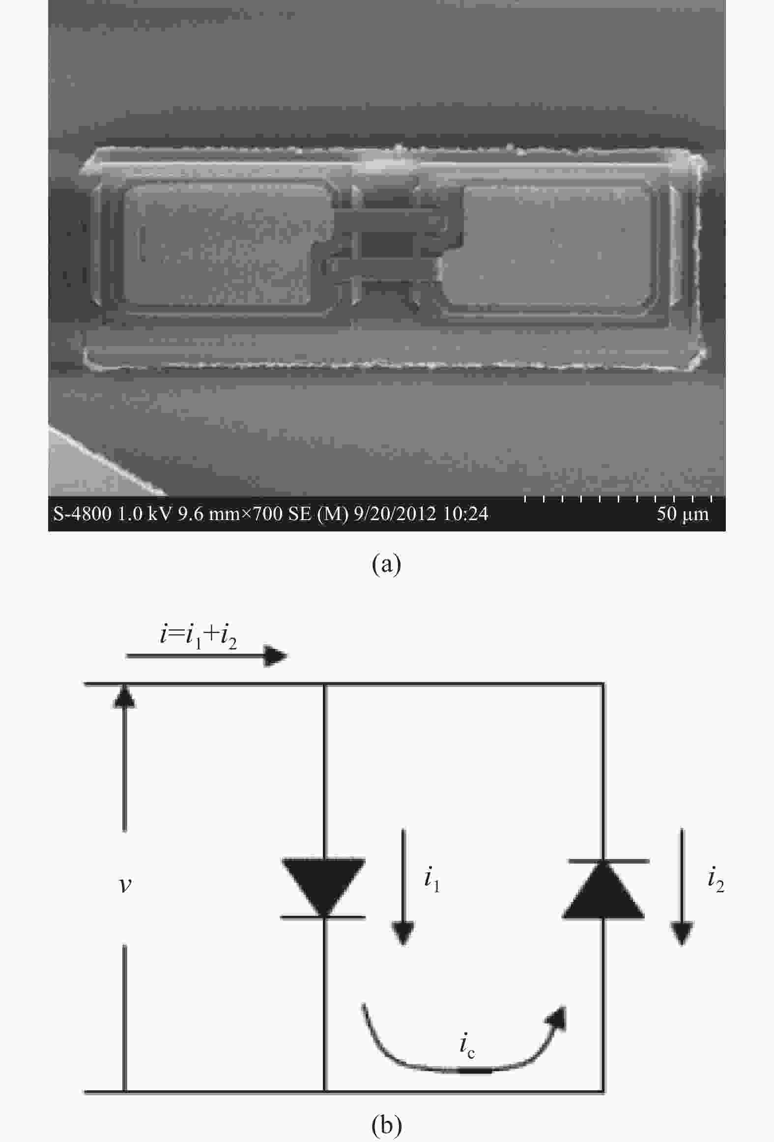
图 1 二极管芯片图片(a)及其电流运动特性(b)
Figure 1. Photo of the diodes’ chip (a) and its current’s flow (b)
反向并联二极管工作原理已经得到详细分析[7],这里只列出结果:
$$ \begin{aligned} &i=a_{1} \cos \omega_{\mathrm{LO}} t+a_{2} \cos \omega_{\mathrm{s}} t+a_{3} \cos 3 \omega_{\mathrm{LO}} t+ \\ &a_{3} \cos \left(2 \omega_{\mathrm{LO}}+\omega_{\mathrm{s}}\right) t+a_{5} \cos \left(2 \omega_{\mathrm{LO}}-\omega_{\mathrm{s}}\right) t+\cdots \end{aligned} $$ (1) 式中:ωLO为本振信号的角频率;ωs为射频信号频率;an为n阶常系数。当本振(LO)频率与射频(RF)频率的一半接近时,低频分量只有2ωLO–ωs,只需加一个低通滤波器取出中频信号(IF)即可,电路变得简单。由于电路输出只有本振偶次谐波分量,奇次谐波在两个二极管环路运行,输出端的本振谐波分量减半,因此这种电路还具有输出噪声小的特点。这种二次谐波混频电路要求反向并联的两只二极管高度一致,通过将两只二极管一同制造在同一块芯片上,很好地满足了这一要求。
-
340 GHz太赫兹二次谐波混频器的结构采用的是传统电场(E)面腔体剖分式结构:LO信号(WR5标准矩形波导)和RF信号(WR2.8标准矩形波导)从混频器模块腔体相对的面(正反面)平行进入,石英基片微带电路一部分内嵌在横跨LO波导和RF波导的沟道内,另一部分嵌在LO波导与模块腔体侧面低频IF信号通道之间的沟道内,LO和RF波导E面中心和石英基片上表面处在同一个平面上。谐波混频器的LO和RF的横电波(TE)信号转换到石英电路横电磁(TEM)信号采用的是固定调谐方式,即LO和RF的输入波导短路面距离固定,与可调谐输入短路面的方式相比,腔体加工简单。因此,混频器盒体加工只要将腔体按波导E面中心线切割成上下两个腔体,石英电路安装在下腔体横跨波导的槽内,如图2所示。

图 2 340 GHz二次谐波混频器结构
Figure 2. Structure of 340 GHz sub-harmonic mixer
可以看出,LO和RF信号通过减高波导探针输入到二极管芯片进行混频,射频滤波器阻止RF信号进入本振端,本振滤波器阻止本振信号和杂散信号进入中频输出端。
-
专用集成电路重点实验室在2013年利用具有阳极端点支撑悬浮空气桥结构的工艺制作技术降低GaAs肖特基二极管的寄生电容,制作出了具有极小寄生电容和串联电阻的太赫兹GaAs肖特基二极管,得到了广泛应用,并且也开展了异构集成和单片应用的探索[10, 12],在应用过程中,二极管模型的建立和使用也日臻成熟。
混频器采用的是阳极结直径为1.3 µm的反向并联二极管,芯片上的单只二极管的重要参数由测试得到:串联导通电阻(Rs)为8 Ω;零偏压结电容(Cj0)为3.2 fF;理想因子(N)为1.2;Vj(势垒结电压)为0.61 V; Is(反向饱和电流)为20 fA。这些参数构成了二极管芯片上单只二极管结的本征参数模型,是非线性电路计算的主要部分。
由于所设计的混频器工作频率高(大于300 GHz),波长小于1 mm,而二极管芯片尺寸为160 µm×50 µm,芯片长度尺寸为工作信号波长的1/5,寄生参数具有强烈的非线性效应,因此计算混频器性能只依靠管芯SPICE 参数等效电路模型就会产生较大的偏差。解决这一问题有效的方法是3D模型提取寄生参数法建立二极管芯片的模型:按照二极管芯片材料和结构建立电磁仿真三维结构模型,将三维电磁仿真软件仿真出的芯片三维结构S参数导出为SNP文件格式,导入非线性电路分析软件,加载二极管结管芯SPICE模型,实现波端口(三维电磁仿真软件激励端口)与非线性结(非线性仿真软件二极管模型)连接,构建二极管芯片完整仿真模型。这种模型可以准确地模拟高频条件下二极管结构对电磁场的影响,提高混频器仿真精度。
场仿真软件不能单独建立与外部空间隔绝的内部端口,可以通过对二极管三维结构进行不影响仿真结果的合理修改:三维结构模型中空气桥阳极柱穿过外延层,延伸到缓冲层上顶端,如图3所示,在缓冲层与金属阳极柱接触表面建立端口。波端口设置为围绕金属阳极柱接触缓冲层面上的圆环,圆环内圆为阳极结。通过三维电磁场仿真得到一个四端口器件在工作频率上的电磁效应,形成一个S4P参数包,两个端口为二极管芯片的输入输出端,另外两个端口为与二极管结的连接端。

图 3 二极管芯片模型(a)和端口结构(b)
Figure 3. Picture of diodes chip's model (a) and structure of anode's port (b)
-
混频器的作用是将本振信号(LO)和射频信号(RF)匹配到二极管上,通过二极管芯片的非线性产生尽可能多的中频信号(IF)输出,同时抑制谐杂波信号进入中频输出。传统的整体仿真方法是将混频电路以二极管芯片为中心向外延伸,按功能进行分解成各个功能模块,对各个功能模块单独仿真,形成代表其功能的S参数包文件,导入电路分析软件进行谐波平衡法仿真优化。
在混频电路仿真中,本振输入阻抗匹配、射频输入阻抗匹配以及本振射频低通滤波器是混频电路仿真的重要任务。滤波器抑制相关频率分量,提高空闲频率分量能量的再利用降低混频电路的变频损耗。设计中,将本振和射频阻抗匹配与输入探针匹配在仿真中同时进行,实现本振和射频信号与二极管的阻抗匹配和输入阻抗的最佳匹配。本振双工器功能为实现本振信号的输入匹配,同时保证本振信号和中频信号的隔离,仿真结果为本振端口的本振输入频率在150~200 GHz频段内反射系数小于−10 dB,本振端口和中频端口实现高于30 dB的隔离。射频输入的仿真结果为射频(RF)频率在300~370 GHz频率范围内反射系数小于−13.7 dB。
将混频器各个功能模块通过电磁仿真输出的SNP文件(S参数包)导入到非线性电路,通过匹配单元与完整的二极管模型结合,进行整体谐波优化仿真得到计算最佳结果后,将匹配单元代入各个功能模块再进行场仿真形成新的SNP文件(S参数包),再次迭代到非线性电路仿真软件,图4为混频器整体模型。通过计算得到最后结果:当本振功率为4 dBm时,混频器在320~360 GHz带宽范围内,变频损耗仿真优化计算结果小于8 dB,最低6.9 dB。

图 4 混频器整体仿真模型
Figure 4. Whole simulation diagram of the mixer
-
混频电路制作在厚度为50 μm的石英基片(介电常数为3.78)上,反向并联结构的二极管芯片使用导电银胶通过倒装焊(flip-chipped)工艺粘在石英基片上的微带线上,实物和内部结构照片如图5所示。
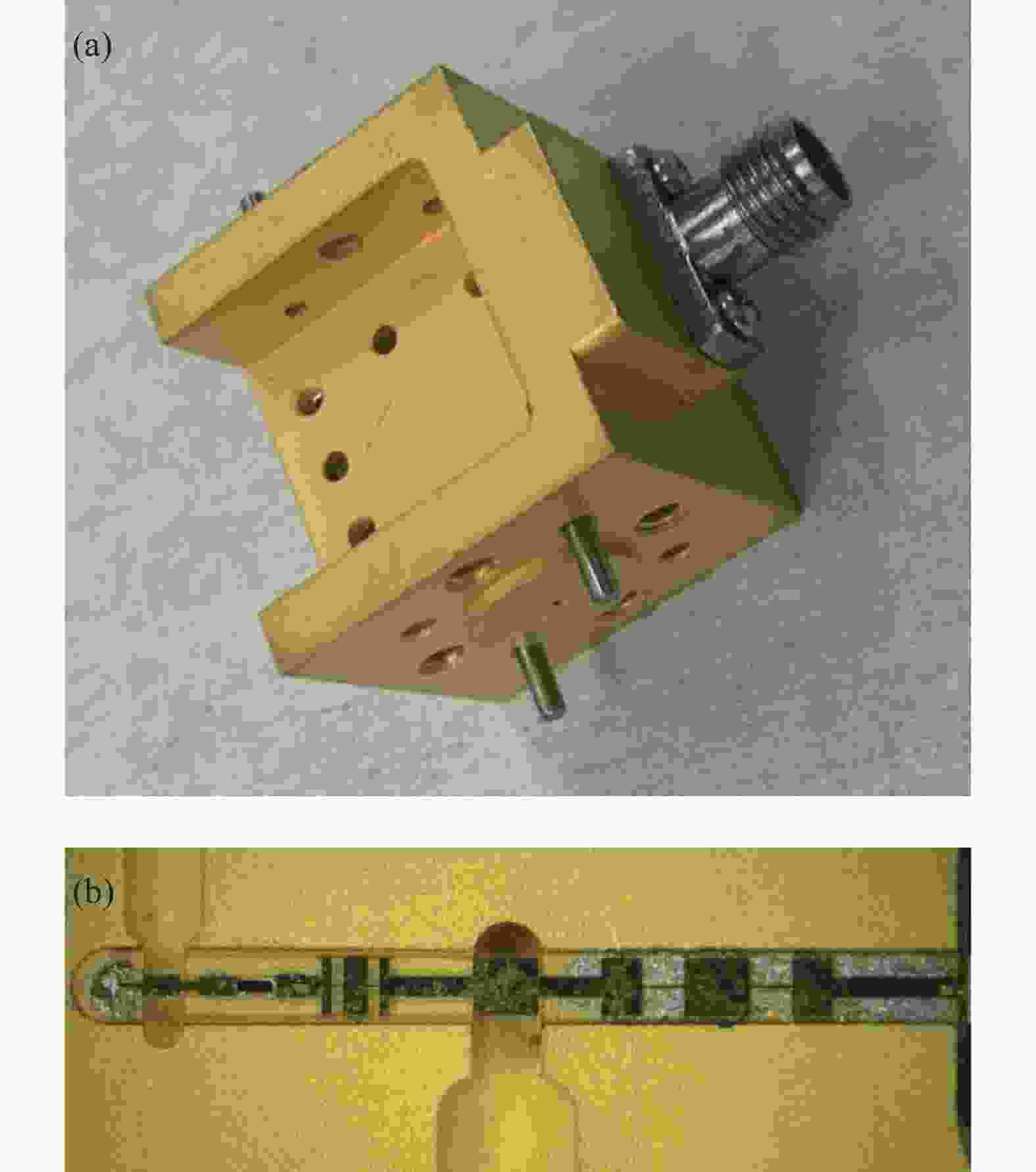
图 5 (a)混频器实物照片; (b)混频器内部结构照片
Figure 5. (a) Photo of the mixer; (b) Inner structure of the mixer
-
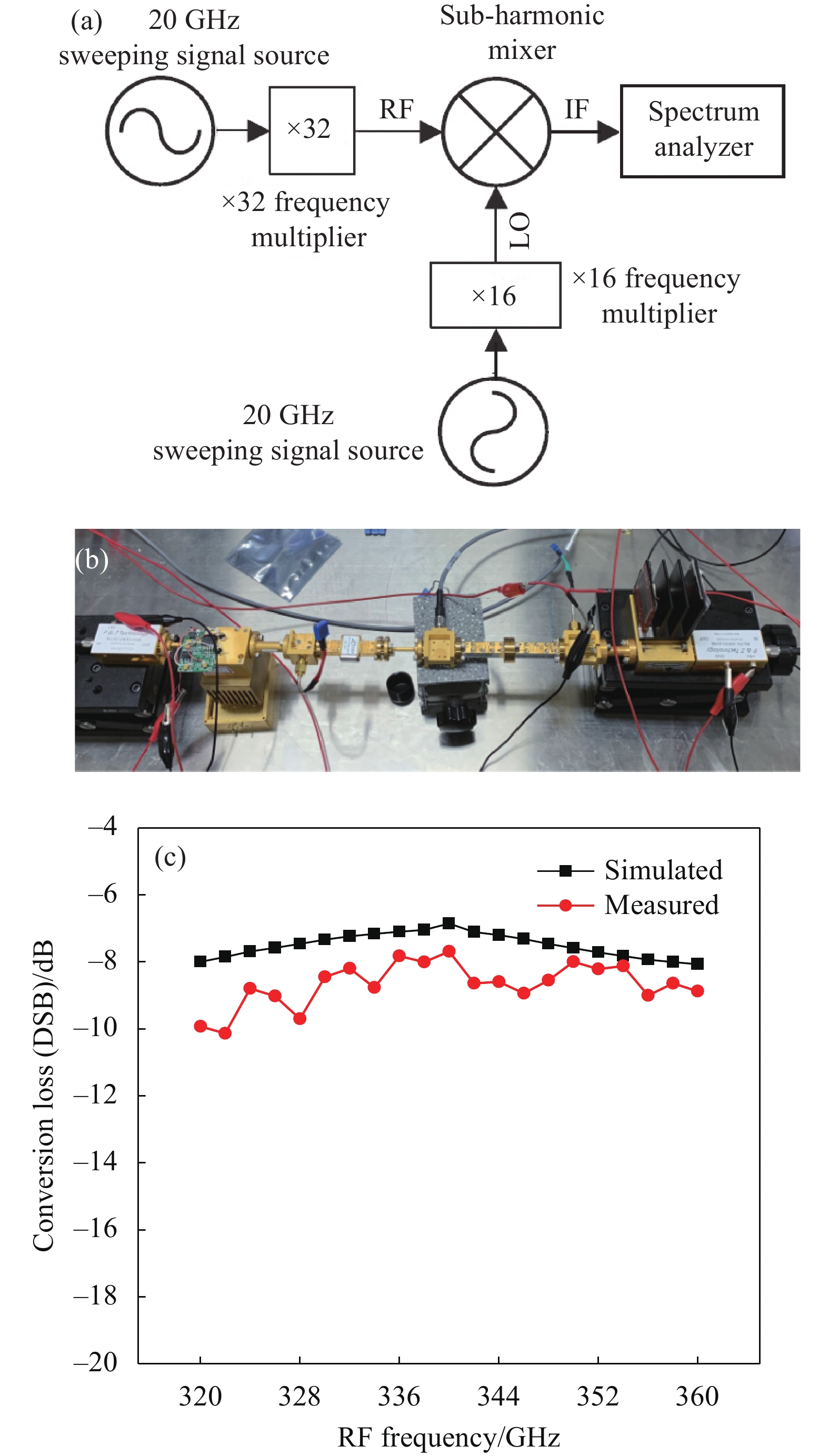
谐波混频器变频损耗(conversion loss)的测试方案如图6(a)所示。射频信号由笔者课题组研制的340 GHz 32倍频组件提供,在320~360 GHz频带范围内均有接近1 mW的功率输出,倍频器输出端连接功率衰减器,起到隔离和将射频输入功率调到接近仿真优化数值的双重作用;本振信号由所研制的16次倍频构成的170 GHz组件提供,在160~180 GHz频带范围内输出功率均大于10 mW,输出端加衰减器调节到本振所需的输入功率。

图 6 (a)测试系统框图;(b)变频损耗测试平台照片; (c)变频损耗仿真和测试曲线
Figure 6. (a) Block diagram of the test platform; (b) Photo of the conversion loss test platform; (c) Simulation and measured results of the conversion loss
变频损耗测试平台如图6(b)所示,RF和LO功率采用太赫兹功率计(PM5)进行标定,测试时RF信号在0.1~0.01 mW范围,功率计取2 mW档,读取小数点后三位作为RF信号标定值,为防止功率计精度对测试影响,进行两次测量取均值作为RF信号功率值。功率读值精度对混频器变频损耗指标测试很关键,这是由于RF信号功率较小,当取值为小数点后两位时,会出现0.005 mW和0.014 mW值都被读为0.01 mW,功率计的这种四舍五入取值会对变频损耗计算值造成高达3 dB的误差,在测试时需要重视。输出IF信号用频谱进行读取,其单位为dB,频谱取值已为多次扫描取平均值,因此中频输出数值取小数点后一位即可。
LO信号输入功率太低则变频损耗差,太高则会对混频二极管造成损坏,设计和测试表明LO信号功率值在5~8 mW范围变化时,变频损耗指标基本不受LO信号功率值影响,混频器正常工作。测试结果如图6(c)所示,在330~360 GHz频带范围内,变频损耗小于9 dB,达到同时期国外VDI公司的产品水平[14]。测试结果与仿真结果相比差损略差,分析原因是二极管芯片和石英电路装配时与仿真模型有差距,致使实际插损略高。
-
接收机等效噪声温度是检验接收机性能的一项重要指标,表征其可探测到信号的最低功率数值。在太赫兹频率超外差接收机应用中,一般接收信号通过天线后直接连接混频器,因此接收系统的等效噪声温度取决于所用太赫兹混频器的性能。
Y因子测试法是目前测量接收机系统等效噪声温度最为通用的测试方法之一[14]。Y因子定义为在不同环境温度下(通常为冷温度Tcold 及热温度Thot)接收机输出功率的比值,如公式(1)所示。测试时设定Tcold为室内常温,将混频器接入接收机系统,首先测试常温时的噪声功率Ncold;黑体加热到标定温度(Thot)稳定后,测得高温时的噪声功率为Nhot,按照公式 (2)得到接收机系统的噪声温度(TDUT):
$$ Y = N_{{\rm{hot}}}/N_{{\rm{cold}}} $$ (2) $$ T_{{\rm{DUT}}}=(T_{{\rm{hot}}}-YT_{{\rm{cold}}})/(Y-1) $$ (3) 通过Y因子噪声测试方法对研制的谐波混频器进行了噪声温度测试,结果如图7所示。测试结果表明,谐波混频器在30 GHz带宽的范围内,双边带噪声温度低于1250 K,在310 GHz处最低为780 K,与国外同频段相比具有一定差距。当测试使用不同增益天线时,对测试结果影响较大,这主要是因为黑体发射的噪声信号被接收机接收的越多,测试噪声温度效果越好,因此在测试时尽量选用一些增益高的接收天线;谐波混频器的本振功率也与噪声温度有关,合适的本振功率可以有效地降低噪声温度。
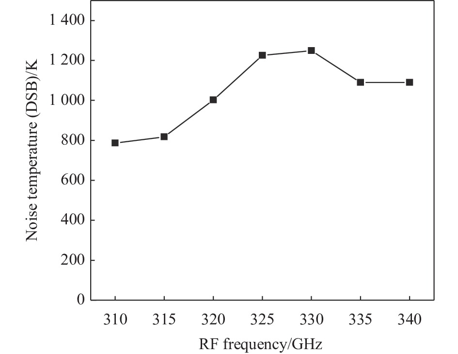
图 7 混频器噪声温度测试结果
Figure 7. Measured result of the mixer’s noise temperature
-
立足于笔者课题组制造的反向并联结构的肖特基二极管芯片,设计和制造了340 GHz谐波混频器。利用芯片的结构和材料构建了它的外围三维电磁仿真模型,结合其非线性电路SPICE模型参数,场路分析结合的方法建立了芯片的完整仿真模型,在此基础上进行对谐波混频器的设计和制造,获得了具有较好性能的太赫兹谐波混频模块。这种二极管芯片建模的方法在许多学术论文中都有提及[10-11, 13],可见其确实能有效地仿真其在太赫兹频段的应用。
研究设计的混频器已经在太赫兹通讯系统得到应用,经测试变频损耗指标效果良好,满足整机系统使用要求。尽管通过一些新的技术手段还可以进一步提高混频器的指标,然而这些技术很多涉及晶圆单片的设计制造,成本较高,作为一种低成本设计简单的方案,石英基片粘结二极管芯片的混合电路设计仍具有巨大的应用价值。这种谐波混频器的成功研制,为亚毫米波、太赫兹频段的固态组件研制提供了一条可行的设计制造流程,为亚毫米波、太赫兹频段模块在雷达、通信等系统中的国产器件推广使用奠定了基础,推进了亚毫米波及太赫兹技术的设计制造发展水平。
A fixed-tuned 340 GHz sub-harmonic mixer
-
摘要: 基于最新研制的小阳极结反向并联肖特基二极管芯片,设计和制造了320~360 GHz固定调谐分谐波混频器。混频器的结构采用的是传统电场(E)面腔体剖分式结构:将二极管芯片倒装焊粘在石英基片上,再用导电银胶将石英电路悬置粘结在混频器下半个腔体上。电路设计采用场路相结合的方法:用场仿真软件建立混频电路各个功能单元的S参数模型,将它们代入非线性电路仿真软件中与二极管结相结合进行混频器性能整体仿真优化。最终测试结果表明,谐波混频器的双边带在4~6 mW的本振功率驱动下,在320~360 GHz超过12%带宽范围内,双边带变频损耗均小于9 dB;混频器在310~340 GHz频带范围内,双边带噪声温度最低为780 K。声温度最低为780 K。Abstract: The design and fabrication of a fixed-tuned 320-360 GHz sub-harmonic mixer, featuring a newly developed small anode junction anti-parallel pair of planar Schottky diodes chip, are presented. A traditional E-plane split-block waveguide architecture was adopted in the mixer's design: the diodes chip was flip-chipped onto a quartz-based microstrip circuit and suspendedly glued to the bottom half of an equally split waveguide block with silver epoxy. A method of combination of field and circuit was applied to simulate and optimize the performance of the mixing circuit. Every functioning part of the mixing circuit was calculated with field simulating software to create its own S-parameters package, which was then combined with the diodes' barriers to be used by nonlinear circuit simulating software to simulate and optimize the performance of the mixer. The final test indicates that the ndicates that the mixer's double side band (DSB) conversion losses were lower than 9 dB, over 12% of bandwidth (320-360 GHz), with 4-6 mW of local oscillator (LO) power input; and at room temperature a minimum DSB equivalent noise temperature of 780 K was measured for RF frequency between 310 GHz and 340 GHz.
-
Key words:
- fixed-tuned /
- sub-harmonic mixer /
- anti-parallel /
- conversion loss
-
图 1 二极管芯片图片(a)及其电流运动特性(b)
Figure 1. Photo of the diodes’ chip (a) and its current’s flow (b)
图 3 二极管芯片模型(a)和端口结构(b)
Figure 3. Picture of diodes chip's model (a) and structure of anode's port (b)
图 5 (a)混频器实物照片; (b)混频器内部结构照片
Figure 5. (a) Photo of the mixer; (b) Inner structure of the mixer
图 6 (a)测试系统框图;(b)变频损耗测试平台照片; (c)变频损耗仿真和测试曲线
Figure 6. (a) Block diagram of the test platform; (b) Photo of the conversion loss test platform; (c) Simulation and measured results of the conversion loss
-
[1] Zhang Jingshui, Kong Lingqin, Dong Liquan, et al. Terahertz CMOS transistor model and experimental analysis [J]. Optics and Precision Engineering, 2017, 25(12): 3128-3136. (in Chinese) doi: 10.3788/OPE.20172512.3128 [2] Liu Xinyuan, Zeng Haomin, Tian Xin, et al. Transmission simulation and safety analysis of terahertz radiation in skin [J]. Optics and Precision Engineering, 2021, 29(5): 999-1007. (in Chinese) doi: 10.37188/OPE.20212905.0999 [3] Dong Zhuo, Chen Jie, Zhu Yifan, et al. Room-temperature terahertz photodetectors based on black arsenic-phosphorus [J]. Chinese Optics, 2021, 14(1): 182-195. (in Chinese) doi: 10.37188/CO.2020-0175 [4] Wang Xiaodong, Yan Wei, Li Zhaofeng, et al. Application of planar antenna in field-effect transistor terahertz detectors [J]. Chinese Optics, 2020, 13(1): 1-13. (in Chinese) doi: 10.3788/co.20201301.0001 [5] Liu Zhaoguo, Zhou Huanli, He Weidi, et al. Development of terahertz detectors with low dimensional materials [J]. Infrared and Laser Engineering, 2021, 50(1): 20211015. (in Chinese) doi: 10.3788/IRLA20211015 [6] Lian Yuxuan, Feng Wei, Ding Qingfeng, et al. 340 GHz wireless communication receiving front-ends based on AlGaN/GaN HEMT terahertz detectors [J]. Infrared and Laser Engineering, 2021, 50(5): 20210202. (in Chinese) doi: 10.3788/IRLA20210202 [7] Thomas B, Maestrini A, Beaudin G. A low-noise fixed-tuned 300–360-GHz sub-harmonic mixer using planar Schottky diodes [J]. IEEE Microwave and Wireless Componts Letters, 2005, 15(12): 865-867. doi: 10.1109/LMWC.2005.859992 [8] Mehdi I, Marazita S M, Humphrey D A, et al. Improved 240-GHz subharmonically pumped planar Schottky diode mixers for space-borne applications [J]. IEEE Transactions on Microwave Theory and Techniques, 1998, 46(12): 2036-2042. doi: 10.1109/22.739280 [9] Schlecht E, Gill J, Dengler R, et al. A unique 520-590 GHz biased subharmonically-pumped Schottky mixer [J]. IEEE Microwave and Wireless Components Letters, 2007, 17(12): 879-881. doi: 10.1109/LMWC.2007.910506 [10] Liu Ge, Zhang Bo, Zhang Lisen, et al. 0.42 THz subharmonic mixer based on 3D precisely modeled diode [J]. J Infrared Millim Waves, 2018, 37(3): 338-343. (in Chinese) [11] Hu Haifan, Zhao Ziran, Ma Xuming, et al. Reasearch on 250 GHz sub-harmonic mixer based on GaAs Schottky diodes [J]. Infrared and Laser Engineering, 2019, 48(7): 0722001. (in Chinese) doi: 10.3788/IRLA201948.0722001 [12] Liu Ge, Zhang Bo, Zhang Lisen, et al. 330 GHz GaAs monolithic integrated sub-harmonic mixer [J]. J Infrared Millim Waves, 2017, 36(2): 252-256. (in Chinese) [13] VDI. Custom transmit and receive systems from 50 GHz to 3 THz [EB/OL]. [2022-04-08]. https://www.vadiodes.com/en/. [14] 杨晓帆. 基于平面肖特基二极管的太赫兹分谐波混频器研究[D]. 成都: 电子科技大学, 2012. Yang Xiaofan. Study on terahertz subharmonic mixer based on the planar schottky diode[D]. Chengdu: University of Electronic Science and Technology of China, 2012. (in Chinese) -

 点击查看大图

计量
- 文章访问数: 208
- HTML全文浏览量: 75
- PDF下载量: 54
- 被引次数: 0


