


 下载:
下载:


-
电场传感器在电力、大气和海洋电场测量等领域有着广阔的应用前景。例如,在电力系统中,电场传感器可以应用于仪器的过电压监测,电气设备附近的瞬态强电场测量和电场分布测量;在大气环境测量中,电场传感器可用于定位雷暴云位置和雷击预警;在海洋环境测量中,电场传感器可应用于研究海底矿物质分布、轮船活动等[1-3]。但应用于这些领域的电学电场传感器需要外部电源驱动,导致无法长时间工作,并且传感器内部的金属部件会对被测电场产生干扰[4]。而光学电场传感器是无源器件不需要外部供电,能长时间工作;又因传感器内部使用的金属部件少,相比于电学电场传感器对被测电场的干扰小。
目前光学电场传感器主要分为集成光学电场传感器与电光晶体电场传感器两类。自1980年美国海军实验室的Bulmer研制出将光波导和偶极子天线结合在一起的集成光学电场传感器[5],研究人员为实现集成光学电场传感器的工程应用,对其灵敏度、带宽、温度稳定性等进行了深入研究[6-10]。1989年,日本东京大学的Hidaka.K等研制了电光晶体传感器[11]。相比于集成光学电场感器,电光晶体传感器为全介质结构,具有对被测电场干扰小的优点,国内外对其展开了研究[12-13]。从2008年起,法国萨瓦大学的Gaborit.G等就开始了电光晶体传感器的研究,该团队研制的二维电场传感器可以同时测量二维电场的大小和方向,精度分别为0.5 dB和2°[14]。2019年,重庆大学的杨庆研制一种双晶体共轭补偿结构的电场传感器,在宽温度范围内测量误差小于5%,可广泛应用于测量强瞬态电场[15]。2020年,该团队研制出沿铌酸锂晶体z轴通光的宽温区电场传感器,该传感器的静态工作点能在0~50 ℃内保持稳定,同时还通过在晶体表面镀制金属电极来提高传感器的灵敏度,其灵敏度为0.64 mV/(kV·m−1)[16]。2021年,昆明理工大学张元英等研制的保偏光纤耦合电场传感器,其线性可测范围为10.5~527 kV/m,灵敏度为0.453 mV/(kV·m−1)[17]。2021年,浙江大学林飞宏研制的反射式光学电场传感器可以测量10−3~102 kV/m的电场,能够应用于高功率微波探测和ns级暂态电场监测[18]。电光晶体电场传感器的灵敏度相比于集成光学电场传感器低10倍左右,限制了其检测微弱电场的能力。但目前对电光晶体传感器的研究大多集中于如何提高传感器温度稳定性的研究,而对提高传感器灵敏度的研究较少。
文中理论和仿真分析了晶体的几何尺寸对传感器灵敏度的影响。提出在晶体长度一定时,可以通过增大晶体宽度,同时减少晶体厚度来提高传感器灵敏度。基于晶体尺寸对晶体内部电场强度影响的仿真结果,设计并研制了三只长度相同、宽度和厚度不同的铌酸锂晶体电场传感器。通过搭建工频电场实验测试平台,对传感器灵敏度进行测试。
-
铌酸锂晶体电场传感器的结构如图1所示,由起偏器、检偏器、1/4波片、铌酸锂晶体组成。起偏器和检偏器的中心轴与铌酸锂晶体的通光方向(晶体光轴为z轴)在同一条直线上,外加电场方向沿铌酸锂晶体y轴,起偏器与检偏器透射光的偏振方向分别与铌酸锂晶体的y轴成45°和−45°。

图 1 电场传感器结构示意图
Figure 1. Schematic diagram of electric field sensor structure
通过起偏器的光变为线偏振光入射到1/4波片变为圆偏振光,沿z轴入射到晶体中正交分解为沿晶体x轴和y轴振动的两束线偏振光。当外加电场方向与晶体y轴平行时,根据铌酸锂晶体的线性电光效应,铌酸锂晶体x轴和y轴的折射率分别为:
$$ \begin{gathered} n_x' \approx {n_o} + \frac{1}{2}{\gamma _{22}}n_o^3{E_{int}} \\ n_y' \approx {n_o} - \frac{1}{2}{\gamma _{22}}n_o^3{E_{int}} \\ \end{gathered} $$ (1) 式中:γ22为电光系数;no为寻常光的折射率。光通过铌酸锂晶体后产生的相位差为:
$$ \varphi (E) = \frac{{2{\text{π }}}}{{{\lambda _0}}}{\gamma _{22}}n_o^3L{E_{int}} $$ (2) 式中:Eint为晶体内部电场强度;λ0为光的中心波长;L为晶体长度。经电场调制后从铌酸锂晶体中输出的光变化为椭圆偏振光。检偏器将光的偏振态变化转换为光强的变化。铌酸锂晶体电场传感器输出光功率Pout为[15]:
$$ {P_{out}}{\text{ = }}\frac{{{P_{in}}}}{{2\alpha }}\left\{ {1 - b\cos \left[ {{\varphi _0} + \varphi \left( E \right)} \right]} \right\} $$ (3) 式中:Pin为输入光功率;α为传感器光路损耗系数;b为传感器整体消光比;φ0为传感器静态工作点。将公式(2)代入公式(3)中得出:
$$ {P_{out}} = \frac{{{P_{in}}}}{{2\alpha }}\left[ {1 - b\cos \left( {{\varphi _0} + \frac{{2{\text{π }}}}{{{\lambda _0}}}{\gamma _{22}}n_o^3L{E_{int}}} \right)} \right] $$ (4) 因传感器中有1/4波片,令公式(4)中φ0=π/2,将传感器的静态工作点调制到线性工作区域。因2πγ22
$n_o^3 L $ /λ0<<1,所以传感器输出光功率表示为:$$ \begin{gathered} {P_{out}} = \frac{{{P_{in}}}}{{2\alpha }}\left[ {1 + b\sin \left( {\frac{{2{\text{π }}}}{{{\lambda _0}}}{\gamma _{22}}n_o^3L{E_{int}}} \right)} \right] \approx \\ \frac{{{P_{in}}}}{{2\alpha }}\left( {1 + \frac{{2b{\text{π }}}}{{{\lambda _0}}}{\gamma _{22}}n_o^3L{E_{int}}} \right) \\ \end{gathered} $$ (5) 因此,从公式(5)中可以得出传感器输出光功率与晶体内部电场强度成线性关系。
-
传感器系统如图2所示,由激光源、铌酸锂晶体电场传感器、光电探测器(Photodetector, PD)、示波器组成。激光源输出的光经通过单模光纤(Single Mode Fiber, SMF)经准直器传输进电场传感器中,因铌酸晶体的线性电光效应,铌酸锂晶体受到外界电场的调制内部传输光的偏振态发生变化。当光通过检偏器时偏振态变化转换为光强度的变化,由准直器将光耦合进SMF传输到光电探测器中,使光强的变化转化为电压的变换。电压信号经射频线传输到示波器中进行信号提取。
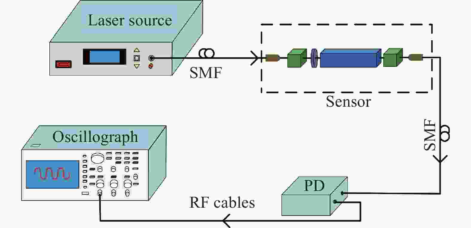
图 2 传感器系统示意图
Figure 2. Schematic diagram of sensor system
传感器系统的输出电压信号Vout为:
$$ {V_{out}} \approx \frac{{A{P_{in}}}}{{2\alpha }}\left( {1 + \frac{{2b{\text{π }}}}{{{\lambda _0}}}{\gamma _{22}}n_o^3L{E_{int}}} \right) $$ (6) 式中:A为光电探测器的电光转换系数。但铌酸锂晶体放置于电场中时,铌酸锂晶体表面会因极化效应产生极化电荷进而形成极化电场Ep[19],且极化电场方向与外加电场方向相反,则晶体内部电场强度可表示为:
$$ \begin{gathered} {E_{int}} = {E_{ext}} - {E_p} = {E_{ext}} - {N_j}{\chi _j}{E_{int}} \\ \end{gathered} $$ (7) 式中:χj为铌酸锂晶体的电极化率;Nj为铌酸锂晶体的极化因子值在0~1之间。由公式(7)可将晶体内外电场比值m可表示为:
$$ m = \frac{{{E_{int}}}}{{{E_{ext}}}} = \frac{1}{{1 + {N_j}{\chi _j}}} $$ (8) 将公式(8)代入到公式(6)中,传感器系统的输出电压信号可写为:
$$ {V_{out}} \approx \frac{{A{P_{in}}}}{{2\alpha }}\left( {1 + \frac{{2b{\text{π }}}}{{{\lambda _0}\left( {1 + {N_j}{\chi _j}} \right)}}{\gamma _{22}}n_o^3L{E_{ext}}} \right) $$ (9) 由公式(9)可将传感器的灵敏度定义为:
$$ S = \frac{{Ab{P_{in}}{\text{π }}}}{{\left( {1 + {N_j}{\chi _j}} \right)\alpha {\lambda _0}}}{\gamma _{22}}n_o^3L $$ (10) 由于公式(10)中Nj值与晶体的几何尺寸相关,理论上当沿外加电场方向即图1中沿y方向的晶体尺寸足够大,同时晶体横截面上沿电场垂直方向即沿图1中沿x轴方向的晶体尺寸足够小时,Nj≈0[19]。此时,由公式(10)可得在晶体长度及其他参数一定的条件下,电场传感器的灵敏度最高。因此,可以通过增加与外加电场平行方向上的晶体尺寸同时减少晶体横截面上与外加电场垂直方向上的晶体尺寸来提高传感器的灵敏度。为此,文中通过仿真并设计制作宽度和厚度不同尺寸的铌酸锂晶体,进一步分析晶体几何尺寸对传感器灵敏度的影响。
-
使用 COMSOL Multiphysics仿真软件建立铌酸锂晶体三维仿真模型如图3(a)所示,平行铜板尺寸为350 mm×350 mm×3 mm,间距d=70 mm。将平行铜板右极板接电压为U,频率为50 Hz的交流电,平行铜板左极板接地,则在极板间形成E=U/d的均匀电场。设沿外加电场方向即晶体y轴方向为晶体宽度w=6 mm、晶体横截面上沿外加电场垂直方向即晶体x轴方向为晶体厚度h=6 mm、沿晶体z轴方向为晶体长度L=42.2 mm,并将晶体放置在两块平行铜板的中间,极板正极加U=7 kV的电压,负极接地,平行极板间电场强度分布图,如图3(b)所示。从图3(b)可知,使用域点探针测得平行铜板间电场约为100 kV/m的匀强电场,但由于晶体表面的极化电荷形成与外界电场相反的极化电场,使得晶体内部电场小于极板间电场,晶体表面电场大于极板间电场。

图 3 (a) Comsol仿真结构图;(b) 电场强度分布图
Figure 3. (a) Diagram of Comsol simulation structure; (b) Distribution of electric field intensity
因铌酸锂晶体为单轴晶体,晶体y向和x向的相对介电常数相等且不等于z向相对介电常数,所以分别沿晶体的y向与z向施加电场,并在晶体中心位置设置域点探针,监测晶体内部电场强度变化。如图4(a)所示为铌酸锂晶体L=42.2 mm、w=6 mm,当h从3 mm变化到24 mm时,晶体内部电场强度的变化。从图4(a)可得,当h从3 mm增加到15 mm时,沿晶体y向加电场时,晶体内部电场强度从8570.532 V/m减小到1510.808 V/m;沿晶体z向加电场时,晶体内部电场强度从22388.967 V/m减小到4880.695 V/m。h从15 mm减小到3 mm,晶体内部电场强度提高约5.1倍。并且当h大于15 mm时,电场方向分别沿晶体x向和y向时,晶体内部电场强度变化基本都保持在±200 V/m。由此可知晶体内部电场强度随着厚度的增加而减小并趋于恒定。如图4(b)所示为铌酸锂晶体的L=42.2 mm、h=3 mm,当w从3 mm变化到22 mm时,晶体内部电场强度的变化。从图4(b)可知,沿晶体y向加电场时,晶体内部电场强度从2791.959 V/m增加到38387.549 V/m;沿晶体z向加电场时,晶体内部电场强度从8728.079 V/m增加到95247.030 V/m。内部电场强度约提高约12.3倍。由此得出,晶体内部电场强度与宽度成正比关系。如图4(c)所示,当铌酸锂晶体h=3 mm、w=6 mm,当L从15 mm增加55 mm时,从图4(c)可知,沿晶体x向加电场时,晶体内部电场强度变化基本保持±379 V/m;沿晶体z向加电场时,晶体内部电场强度变化基本保持±12608 V/m。L从15 mm增加55 mm,晶体内部电场强度变化幅度仅约为5%。由此可得晶体长度对晶体内部电场强度的影响较小。综上所述,晶体内部电场强度主要受晶体的厚度和宽度影响。因晶体长度对晶体内部电场的影响较小,所以设置三块长度相同,厚度和宽度不同的晶体来仿真内部电场随外部电场的变化规律。如图4(d)所示,当晶体y轴沿电场方向,右极板上电压从2 kV增加到20 kV,即极板间电场强度从28.571 kV/m增加到285.714 kV/m时,晶体内部电场强度变化与外界电场强度成正比。三种尺寸晶体的内外电场之比分别为0.028、0.090和0.030。分别对比三种尺寸的内外电场比值,尺寸为3 mm×6 mm×42.2 mm的内外电场强度之比是晶体尺寸为3 mm×3 mm×42.2 mm和6 mm×6 mm×42.2 mm的3倍。由此得出晶体越宽越薄,其晶体内部电场强度越高。将三种尺寸下内外电场之比分别代入到公式(10),同时考虑到传感器实验系统中的A=687.936 mV/mW,Pin=2.5 mW,α=1,b=1,γ22= 6.81×10⁻¹² m/V,no=2.212,计算三只传感器的灵敏度分别为0.304、0.976、0.325 mV/(kV·m−1)。因此,在晶体长度一定时,晶体宽度尺寸越大,厚度尺寸越小,其传感器灵敏度越高。

图 4 晶体内部电场强度仿真
Figure 4. Simulation of electric field intensity inside crystal
-
电场传感器由SMF准直器、PBS、四分之一波片、铌酸锂晶体和使用光敏树脂材料制作的底座和封装壳组成。单模光纤准直器由SMF-28 E光纤和G型准直透镜组成,其耦合距离为21 mm,输出平行光的光斑直径大小为0.5 mm;起偏器和检偏器选用偏振分束器(Polarization Beam Splitter, PBS),其透射光为线偏振光;1/4波片是适用于波长为1550 nm的零级型波片;选用同一批次的铌酸锂晶体,尺寸分别为3 mm×3 mm×42.2 mm、3 mm×6 mm×42.2 mm、6 mm×6 mm×42.2 mm (x×y×z)。图1中,将器件安装于底座上,确保光纤准直器输出面和PBS、1/4波片、晶体的通光面相互平行且两个PBS透射光偏振方向相互垂直,与铌酸锂晶体y轴分别成45°和−45°,见图5。通过旋转光学调准架控制左右底座的位置,当输出光功率最大时,采用紫外固化胶将底座与封装外壳固定,完成传感器的封装。将激光源输出5 mW的激光通过SMF输入传感器,使用光功率计测得三只传感器的输出光功率分别为1.529 mW、1.075 mW和0.921 mW,对应的耦合效率分别为30.6%、21.5%、18.4%。

图 5 传感器耦合照片
Figure 5. Photograph of the sensor coupling
-
为了实现对传感器灵敏度的测试,搭建了工频强电场实验测试平台,如图6所示。实验测试平台由变压器、变压器输出控制箱、平行极板组成。变压器控制箱接入220 V/50 Hz的交流电,通过控制变压器输出0~16 kV的电压,由铜线连接到平行极板上。平行极板由两块长为350 mm、宽为350 mm、厚为3 mm,间距为70 mm的铜板制成,符合国标GB/T 12720—1991对平板标定尺寸的规定[18]。由此可以在平行极板间产生。将传感器放置于平行铜板中间位置,晶体y轴沿电场方向。

图 6 工频电场试验平台照片
Figure 6. Photo of power frequency electric field test platform
当施加在右极板上电压为4 kV、左极板接地,即极板间形成57.143 kV/m的匀强电场,通过示波器观察到三只传感器探测到的电场波形如图7(a)~(c)所示。从图中得出输出信号峰峰值分别为21.6 mV、48.8 mV和9.44 mV,信号频率分别为50.01 Hz、49.98 Hz和50.00 Hz。传感器的输出还原了频率为50 Hz市电的时域波形。

图 7 57.143 kV/m时传感器输出波形图
Figure 7. Output waveform of sensor at 57.143 kV/m
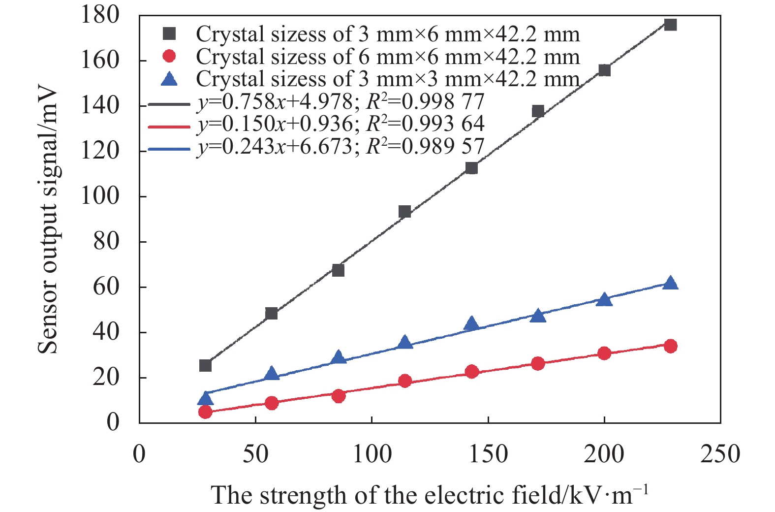
控制变压器输出0~16 kV即形成0~228.571 kV/m的电场,测试三只电场传感器的输出信号,如图8所示。通过输出信号的线性拟合得到晶体尺寸为3 mm×3 mm×42.2 mm (x×y×z),3 mm×6 mm×42.2 mm (x×y×z)和6 mm×6 mm×42.2 mm (x×y×z)的传感器对应的灵敏度分别为0.243 mV/(kV·m−1),0.758 mV/(kV·m−1)和0.150 mV/(kV·m−1)。

图 8 传感器系统输入输出特性
Figure 8. Input and output characteristics of the sensor
通过对比三种电场传感器的输入输出特性曲线,表明在晶体长度相同的条件下,厚度越薄,宽度越宽,晶体传感器灵敏度越大。但是与仿真的灵敏度对比存在差异,分析原因主要是一方面在制作传感器的过程中,光并未垂直入射晶体,从而在晶体中产生自然双折射,使得传感器的静态工作点不完全为π/2进而影响传感器的灵敏度;另一方面传感器的光路耦合过程中也存在一定误差,造成三只传感器耦合效率不同即光路损耗不同,从而影响了传感器灵敏度的大小。
-
文中通过COMSOL仿真分析了铌酸锂晶体厚度、宽度和长度对晶体内部电场强度的影响,得出长度对晶体内部电场强度的影响较小,而晶体宽厚比值越大,晶体内部电场强度越大。测试铌酸锂晶体尺寸分别为3 mm×3 mm×42.2 mm、3 mm×6 mm×42.2 mm和6 mm×6 mm×42.2 mm的三只电场传感器的灵敏度,对应的灵敏度分别为0.243 mV/(kV·m−1)、0.758 mV/(kV·m−1)和0.150 mV/(kV·m−1)。由此可知,当传感器的晶体厚度和长度一致时,可以通过增加晶体宽度来提高传感器的灵敏度;当传感器的晶体宽度和长度一致时,可以通过减小晶体厚度来提高传感器的灵敏度。因此认为可以通过增大晶体宽度和减小晶体厚度的来提高传感器的灵敏度,该方法相比于现有晶体表面敷设电极来提高传感器灵敏度,不仅简化了传感器的制作难度,而且降低了成本。
Analysis of influence of lithium niobate crystal structure on sensitivity of electric field sensors
-
摘要: 铌酸锂晶体光学电场传感器为全介质结构,具有宽带宽、对被测电场干扰小的优点,但其灵敏度较低。因此,分析了晶体几何尺寸对传感器灵敏度的影响机理,得出通过增加沿外加电场方向的晶体尺寸同时减少晶体横截面上沿外加电场垂直方向的晶体尺寸来提高传感器的灵敏度。使用COMSOL仿真分析了铌酸锂晶体不同厚度、宽度、长度对晶体内部电场强度的影响,得出晶体厚度从15 mm减小到3 mm和宽度从3 mm增加到22 mm时,晶体内部电场强度分别提高约5.1倍和12.3倍;晶体长度从15 mm变化到55 mm时,晶体内部的电场强度变化仅约为5%。设计并研制出晶体尺寸分别为3 mm×3 mm×42.2 mm (x×y×z),3 mm×6 mm×42.2 mm (x×y×z),6 mm×6 mm×42.2 mm(x×y×z)的三只铌酸锂晶体电场传感器,并搭建工频电场测试平台,测试得出三只电场传感器的灵敏度分别为0.243 mV/(kV·m−1)、0.758 mV/(kV·m−1)、0.150 mV/(kV·m−1)。当晶体厚度和长度一定且晶体宽度从3 mm增加到6 mm时,传感器灵敏度提高3倍。当晶体宽度和长度一定且晶体厚度从6 mm减小到3 mm时,传感器灵敏度提高5倍。结合仿真与实验结果得出:在晶体长度一定时,可以通过设计使用宽度更宽、厚度更薄的晶体,研制出高灵敏度的电场传感器。Abstract: The lithium niobate crystal optical electric field sensor has the advantages of wide bandwidth and negligible interference to the original electric field due to its all-dielectric structure. But it has low sensitivity to measure the electric field. The influence mechanism of crystal geometry size on sensor sensitivity is analyzed. The sensitivity of the sensor is improved by increasing the crystal size along the direction of the applied electric field and reducing the crystal size along the vertical direction of the applied electric field on the crystal cross-section. The influence of different thickness, width and length of the crystal on the internal electric field intensity has been analyzed using COMSOL simulation, and it is concluded that the internal electric field intensity of the crystal increases by about 5.1 times and 12.3 times when the thickness decreases from 15 mm to 3 mm and the width of the crystal increases from 3 mm to 22 mm, respectively. When the length of the crystal increases from 15 mm to 55 mm, the internal electric field intensity of the crystal changes by only about 5%. Three lithium niobate crystal electric field sensors with crystal sizes of 3 mm×3 mm×42.2 mm (x×y×z), 3 mm×6 mm×42.2 mm (x×y×z) and 6 mm×6 mm×42.2 mm (x×y×z) have been designed and developed, the sensitivities are 0.243 mV/(kV·m−1), 0.758 mV/(kV·m−1), 0.150 mV/(kV·m−1), respectively. When thickness and length of the crystal are constant, the sensor sensitivity is increased 3 times with the crystal width increased from 3 mm to 6 mm. When width and length of the crystal are constant, the sensor sensitivity is increased 5 times with the crystal thickness decreased from 6 mm to 3 mm. Combining the simulation and experimental results, it is concluded that a higher sensitivity electric field sensor can be developed by designing the crystal with wider width and thinner thickness under a certain crystal length.
-
Key words:
- optical engineering /
- electric field sensor /
- crystal structure /
- lithium niobate crystal /
- sensitivity
-
图 3 (a) Comsol仿真结构图;(b) 电场强度分布图
Figure 3. (a) Diagram of Comsol simulation structure; (b) Distribution of electric field intensity
-
[1] Yang Qing, Sun Shangpeng, Sima Wenxia, et al. Progress of advanced voltage/current sensing techniques for smart grid [J]. High Voltage Technology, 2019, 45(2): 349-367. (in Chinese) [2] Chen Tao, Zhang Xiaoxin, Zhang Xuemin, et al. Imminent estimation of earthquake hazard by regional network monitoring the near surface vertical atmospheric electrostatic field [J]. Chinese Journal of Geophysics, 2021, 64(4): 1145-1154. (in Chinese) doi: 10.6038/cjg2021O0129 [3] Shen Zhen, Song Yusu, Wang Yexuan, et al. Study on the detection characteristics of Ag/AgCl and carbon fiber marine electric field electrodes [J]. Chinese Journal of Scientific Instrument, 2018, 39(2): 211-217. (in Chinese) [4] Zhao M, Zhou X, Chen Y Z. A highly sensitive and miniature optical fiber sensor for electromagnetic pulse fields [J]. Sensor, 2022, 21(23): 2-14. [5] Bulmer C H, Burns W K, Moeller R P. Linear interferometric waveguide modulator for electromagnetic-field detection [J]. Optics Letters, 1980, 5(5): 176-178. doi: 10.1364/OL.5.000176 [6] Wang H, Zeng R, Zhuang C J, et al. Measuring AC/DC hybrid electric field using an integrated optical electric field sensor [J]. Electr Power Systems Research, 2020, 179: 106087. doi: 10.1016/j.jpgr.2019.106087 [7] Zhang J H, Li Y N, Jiang C. Optical waveguide electric field sensor based on dual parallel Mach-Zehnder interferometer [J]. IEEE Sensor Journal, 2021, 21(18): 20099-20106. doi: 10.1109/JSEN.2021.3099975 [8] Zhang J H, Yang L, Li Yingna. Non-invasive measurement of intensive power-frequency electric field using a LiNbO3-integrated optical waveguide sensor [J]. IET Science Measurement Technology, 2021, 15(1): 101-108. doi: 10.1049/smt2.12014 [9] Zhang J H, Chen F S, Liu B. Integrated photonic electric field sensor operating more than 26 GHz [J]. IEEE Microwave and Wireless Components Letters, 2020, 30(10): 1009-1012. doi: 10.1109/LMWC.2020.3019448 [10] Zhang Jianxin, Zhang Jiahong, Chen Fushen. Design and implementation of integrated optical waveguide DC electric field sensor [J]. Acta Photonica Sinica, 2021, 50(5): 0513003. (in Chinese) doi: 10.3788/gzxb20215005.0513003 [11] Hidaka K, Kouno T. A method for measuring electric field in space charge by means of pockels device [J]. Journal of Electrostatics, 1982, 11(3): 195-211. doi: 10.1016/0304-3886(82)90012-2 [12] Huang Yifan, Xu Qifeng, Chen Linyang, et al. Medium enwrapping method for improving internal electric field distribution of OVT [J]. Infrared and Laser Engineering, 2017, 46(7): 0722004. (in Chinese) doi: 10.3788/IRLA201746.0722004 [13] Tan Qiao, Xu Qifeng, Xie Nan, et al. Quantitative research on the intrinsic linear birefringence and temperature characteristic of BGO crystal [J]. Infrared and Laser Engineering, 2016, 45(6): 0622004. (in Chinese) doi: 10.3788/IRLA201645.0622004 [14] Gaborit G, Jarrige P, Lecoche F. Single shot and vectorial characterization of intense electric field in various environments with pigtailed electrooptic probe [J]. IEEE Transactions on Plasma Science, 2014, 42(5): 1265-1273. doi: 10.1109/TPS.2014.2301023 [15] Yang Q, Sun S P, He Y X, et al. Intense electric-field optical sensor for broad temperature-range applications based on a piecewise transfer function [J]. IEEE Transactions on Industrial Electronics, 2019, 66(2): 1648-1656. doi: 10.1109/TIE.2018.2831170 [16] Sun Shangpeng, Yang Qing, He Yanxiao, et al. Intense electric-field sensor for broad temperature-range applications based on the electro-optic Interferometer of bulk lithium niobate [J]. High Voltage Technology, 2020, 46(6): 1913-1921. (in Chinese) [17] Zhang Yuanying, Zhang Jiahong, Li Yingna, et al. Polarization-maintaining fiber coupling type LiNbO3 intensive power frequency electric field sensor [J]. Chinese Journal of Scientific Instrument, 2021, 42(6): 272-278. (in Chinese) doi: 10.19650/j.cnki.cjsi.J2107779 [18] Lin Feihong, Zhou Ji, Zhang Jianpei, et al. Reflective miniature optical electric field sensor [J]. Journal of Zhejiang University (Engineering Science), 2021, 55(11): 2207-2214. (in Chinese) [19] Kip A F. Fundamentals of Electricity and Magnetism[M]. 2nd ed. New York: McGraw-Hill, 1969. -

 点击查看大图

图(8)
计量
- 文章访问数: 257
- HTML全文浏览量: 50
- PDF下载量: 45
- 被引次数: 0


