


-
大气风场是深入研究大气动力学、全球大气活动和空间环境预警的重要参数之一[1]。长期以来,由于对流层和平流层大气的复杂及变化多端,探测较为困难[2]。目前,人们通过多种手段来测量大气风场,并取得了积极的进展。风场数据主要来自无线电探空仪、探空火箭、微波雷达及卫星遥感等,但这些手段存在连续性差、时空分辨率低等问题[3]。多普勒测风激光雷达作为唯一能够对大范围三维风场实现高精度、高时空分辨率探测的工具[4],具有空间分辨率高、连续测量、机动性好等特点,成为近年来大气探测领域的研究热点,应用前景十分广阔[5]。
多普勒测风激光雷达可分为相干探测激光雷达和直接探测测风激光雷达[5]。相干探测多普勒激光雷达系统具有很高的探测灵敏度,目前已广泛用于风电场、机场航空等领域。由于大气湍流对激光相干性的破坏,以及只能利用气溶胶米散射信号,它的有效探测距离受到限制。而直接测风激光雷达可以针对不同的高度,使用不同的方式进行探测,若仅以气溶胶为探测目标,则可以探测低层大气风场;若仅以大气分子为探测目标,则可以探测中高层大气风场。因此,直接探测多普勒激光雷达具有覆盖对流层和平流层高度范围风场探测的潜力。
法国普罗旺斯重点实验室建立的基于法布里-珀罗标准具的双边缘探测技术的532 nm瑞利-米多普勒激光雷达系统(OHP)探测范围25~60 km,改进后的第二代系统探测范围8~50 km[6];美国NASA Goddard航天中心大气实验室研制的基于三通道法布里-珀罗标准具双边缘技术的355 nm瑞利散射多普勒激光雷达系统(GLOW)探测范围1.8~35 km[7]。国内直接探测的典型系统有:中国海洋大学刘智深教授组建的基于532 nm碘分子吸收谱线边缘鉴频技术的多普勒激光雷达系统,并报道了低对流层风速分布[4];中国科学院安徽光学精密机械研究所建成的基于法布里-珀罗标准具双边缘技术的1064 nm米散射多普勒激光雷达系统,探测范围0.2~10 km[8-9];中国科学技术大学研制成功的两套基于三通道法布里-珀罗标准具双边缘技术的355 nm瑞利测风激光雷达系统[10],探测范围分别为10~40 km和15~60 km。
文中研制了一台对流层和平流层多普勒直接测风激光雷达系统,采用旋转转台式探测结构,并采用频率跟踪的方法实现对流层和平流层大气风场的准确测量。详细介绍了系统结构和设计参数,并开展了一系列相关实验。
-
直接测风激光雷达的基本原理是利用窄线宽的激光与大气相互作用产生的后向散射回波信号,望远镜系统接收后经过光纤传入接收系统中,由接收系统提取多普勒信息,进而得到大气风场的信息[11]。
在激光雷达探测过程中,激光与大气粒子之间相互作用。由于粒子的运动造成望远镜接收光的频率发生变化,多普勒频移通过接收和发射光的频率变化计算得到[9],经过计算多普勒频移量可反演粒子的运动速度和方向,经过合成后即水平大气风场的风速和风向。
从运动参考系中观测到的频率
$v'$ 为[10]:$$ v' ={v}_{0}(\text{1}+V \cos{\theta }_{i}/c)$$ (1) 式中:
$ {v_0} $ 为出射激光频率;$ V $ 为散射粒子的运动速度;c为光速;$ {\theta _i} $ 为入射光与移动方向的夹角。发生频移之后,多普勒频移
$ {v_d} $ 为:$$ {v_d} = {v^\prime } - {v_0} = {v_0}V\left( {\cos {\theta _i} + \cos {\theta _r}} \right)/c $$ (2) 式中:
$ {\theta _r} $ 为激光雷达接收方向与粒子移动方向的夹角。由于激光雷达为收发合置系统,得到$ {\theta _i} = {\theta _r} = \theta $ ,公式(2)可以简化为[11]:$$ {v_d} = {v_0}2V\cos \theta /c = 2{V_r}/{\lambda _0} $$ (3) 式中:
$ {V_r} = V\cos \theta $ 为矢量径向风速径向分量。得到一个方向的径向风速后,通过测量其他四个方向上的径向风速,从而求得东西南北四个不同方向的径向风速。假设四个方向的径向风速为VrE、VrW、VrS和VrN,则水平风速大小Vh和方向
$ \gamma $ 分别为[11]:$$ {V_h} = \sqrt {V_x^2 + V_y^2} $$ (4) $$ \gamma = \arctan \,({V_x}/{V_y}) + \pi \left\{ {1 - {{\rm{sign}}}\, \left[ {({V_y} + \left| {{V_y}} \right|) \cdot {V_x}} \right]} \right\}$$ (5) 其中,
$ {V_x} $ 和$ {V_y} $ 分别为:$$ {V_x} = ({V_{rE}} - {V_{rW}})/2\sin \theta $$ (6) $$ {V_y} = ({V_{rN}} - {V_{rS}})/2\sin \theta $$ (7) 在直接测风激光雷达中,边缘技术是广泛使用的一种频率检测技术,主要工作原理是将入射光频率的变化转化为光强的变化,从而实现频率检。法布里-珀罗标准具是一种非常有效的检测多普勒频移量的工具,可以获得更加准确的对流层和平流层大气风场数据。
在理想且不考虑多普勒频移的情况下,
$ h(v) $ 为真实的双边缘法布里-珀罗标准具的透过率曲线,计算公式为[10]:$$ \begin{split} h(v) =& {T_p}\left( {\frac{{1 - {R_e}}}{{1 + {R_e}}}} \right)\left\{ 1 + 2\sum\limits_{n = 1}^{ + \infty } {R_e^n} \cos \left( {\frac{{2\pi n(v - {v_p})}}{{\Delta {v_{FSR}}}}\frac{{1 + \cos {\theta _0}}}{2}} \right)\cdot\right.\\ &\left.\exp \left[ - {{\left( {\frac{{\pi n(1 + \cos {\theta _0})}}{{2\Delta {v_{FSR}}}}\Delta {v_R}} \right)}^2}\right] \cdot \operatorname{sinc}\left(\frac{2 m_{m}}{{{{An}}}_{m a}} \frac{1 - \cos \theta_{2}}{2}\right)\right\} \end{split} $$ (8) 式中:
$ \theta_{0} $ 为标准具接收光的光束发散角;$ \Delta {v_R} $ 为后向散射谱谱宽;$ {v_0} $ 为出射光频率,$ \Delta {v_{FSR}} $ 为自由谱间距;$ {T_p} $ 为峰值透过率;$ {R_e} $ 为有效反射率。大气中的温度会影响分子之间的热运动和碰撞,从而影响回波信号的展宽。因此,温度对于回波信号的影响可以由如下高斯函数表示[12]:$$ {f_{Ray}}(\nu ) = \sqrt {\dfrac{{4\ln 2}}{{\pi \Delta \nu _r^2}}} {{\rm{e}}^{ - \tfrac{{4\ln 2}}{{\Delta \nu _r^2}}{\nu ^2}}} $$ (9) $$ \Delta {\nu _r} = \sqrt {\frac{{32kT\ln 2}}{{{\lambda ^2}M}}} $$ (10) 式中:
$ \Delta {\nu _r} $ 为瑞利散射光信号的谱宽度;M为平均大气分子质量;T为散射分子的温度;k为玻耳兹曼常数。为了得到实际测量的多普勒频移,根据上述公式可得,实际测量的标准具的透过率
$ {T_R}(\nu ) $ 可以表示为[13]:$$ {T_R}(\nu ){{ = h}}(\nu ) \otimes {f_{Ray}}(\nu ) \otimes {f_{Mie}}(\nu ) $$ (11) 式中:
$ {f_{Ray}}(\nu ) $ 和${{h}}(\nu )$ 均可从公式(9)和公式(8)得到;$ {f_{Mie}}(\nu ) $ 为激光发射谱线;“$ \otimes $ ”为卷积符号。根据标准具的透过率函数,可以定义频率响应函数。根据实测的透过率大小得到频率响应值,再利用频率响应函数经过反演后,可以得到多普勒频移大小,进而得到反演的径向风速。目前定义频率响应函数有多种方法,为了在计算风速范围内响应函数和多普勒频移接近线性,将频率响应函数定义为[14]:
$$ R(\nu ,T) = \frac{{C{T_{R1}}(\nu ,T) - {T_{R2}}(\nu ,T)}}{{C{T_{R1}}(\nu ,T) + {T_{R2}}(\nu ,T)}} $$ (12) 式中:C为比例修正系数,用于修正光纤分束器的分束比带来的误差。
图1为系统采用的双边缘多普勒直接测风原理图。图中,Etalon1和Etalon2分别代表法布里-珀罗标准具的边缘1通道和边缘2通道的透过率;EtlonL为法布里-珀罗标准具的锁定通道的透过率;Laser代表激光发射谱线;中间的橙色线代表气溶胶和瑞利散射谱线。当大气后向散射回波信号存在多普勒频移时,气溶胶和瑞利散射的谱线会随之移动,边缘1和边缘2通道的透过率一个增大,一个减小,图中阴影部分面积代表透过率曲线、激光发射谱线和散射谱线的卷积,卷积的面积也会一个增大,一个减小[14]。公式(11)反映卷积的面积,代入到公式(12)中,即可以获得不同高度处的多普勒频移,从而求得径向风速。
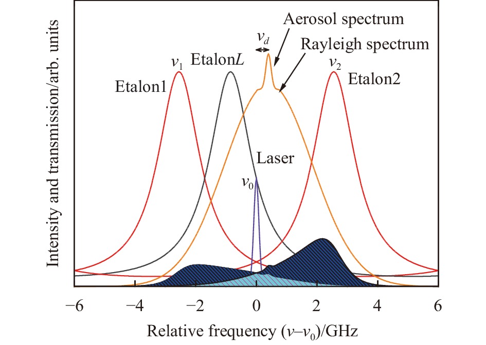
图 1 双边缘多普勒直接测风测量原理图
Figure 1. Principle diagram of double edge Doppler direct wind measurement
-
对流层和平流层多普勒测风激光雷达系统示意图和实物图分别如图2(a)、(b)所示,整个系统采用转台式设计,将方舱固定在圆形转台上,方舱内部包含望远镜、激光器等对应的元器件。

图 2 多普勒直接测风激光雷达系统示意图和实物图
Figure 2. Schematic diagram and physical drawing of Doppler direct wind lidar system
对流层和平流层多普勒测风激光雷达系统结构图如图3所示,种子注入式532 nm的激光器发射激光,大部分激光经过扩束镜入射到大气中,经过望远镜接收。发射激光的一小部分光经过积分球导入到后继光学系统中,另外一部分光导出经过波长计用于出射激光的频率监测。大气回波信号被大口径望远镜接收后,经过准直镜和小孔光阑进入光纤。光纤的位置为接收回波信号的焦点位置,进行对应调整之后可将大气回波信号导入到接收机中,经过对应的反射镜片和法布里-珀罗标准具后,由对应的PMT探测器接收,再通过瞬态记录仪进行信号采集。在测得一个径向风速后,调整转台方向,测量另一个径向风速。当四个径向风速探测完成后,对径向风速合成即可得到水平风速和风向。

图 3 多普勒直接测风激光雷达系统结构示意图
Figure 3. Schematic diagram of Doppler direct wind lidar system structure
系统的设计性能指标如表1所示,风速探测范围0~100 m/s,高度在5 km时,随机风速误差为1 m/s,高度在30 km时,随机风速误差在5 m/s,垂直分辨率为300 m,探测时间为20 min。
表 1 系统探测指标
Table 1. System detection index
System parameters Value Wavelength/nm 532 Energy/mJ·pulse–1 800 Measuring range/km 5-35 Telescope diameter/mm 800 Wind velocity range/m·s–1 0-100 Wind speed detection error 1 m/s@5 km, 5 m/s@25 km Vertical resolution/m 300 Time resolution/min 20 Scanning range/(°) 360 接收机的光路图和三维模型图分别如图4(a)、(b)所示。从系统的发射部分分出的一路光需要接入到接收机中,用于锁定通道透过率的计算。该接收机系统由可调节的反射镜组成,可以对光路的准直性进行调节。望远镜接收的回波信号经过多模光纤导入到准直镜1中,经过准直变成平行光后分为两束光,分光比例为9∶1,即90%的光进入法布里-珀罗标准具的边缘通道,10%的光进入瑞利-米通道,进入探测器接收。该通道一方面可以监测激光器的频率抖动造成的误差,另一方面在系统运行过程中,可以使用该通道来进行查看回波信号的质量。两个边缘通道的光经过分束镜通过法布里-珀罗标准具,经过反射镜2和反射镜4进入对应探测器。从激光器导出的光经过准直镜2进入接收机,经过分光镜1和反射镜1进入法布里-珀罗标准具。分光镜1的分光比例为7∶3,即锁定参考通道接收的光占30%,法布里-珀罗标准具中的锁定通道接收的光占70%,从而计算得到锁定通道的透过率。

图 4 接收机光路图(a)及三维结构图(b)
Figure 4. (a) Optical path diagram and (b) three-dimensional structure diagram of receiver
通常多普勒直接测风激光雷达采用扫描式结构对风速进行测量,该结构需要多余的反射镜,会影响系统的探测效率。如果采用两个固定方舱正交观测的方案,则成本较高。该系统采用旋转转台式结构,解决了传统的扫描头装置无法适用于大口径激光雷达的难题,且仅需要单个设备方舱,有效地降低了成本和运维难度。系统选用的转台直径为6 m,系统定位精度可达到±0.1°,设有绝对零位,可实现360°任意角度可调。转台的减速电机为变频电机,其转速和运转方向由PLC控制,可以实现准确停车,同时尾端装有光电编码器用来检测旋转的角度。
在多普勒激光雷达进行工作时,需要多个硬件进行协调,因此需要对系统的时序进行设计。系统的工作时序图如图5所示。激光脉冲的间隔时间为33 ms,出射激光的脉宽为8 ns,激光出光后,激光器的Q开关输出上升沿TTL电平,此时门控卡开始工作,产生的方波信号进入到PMT探测器中,首先输出低电平,不接收低层信号,随后输出高电平,用于探测高空大气信号。
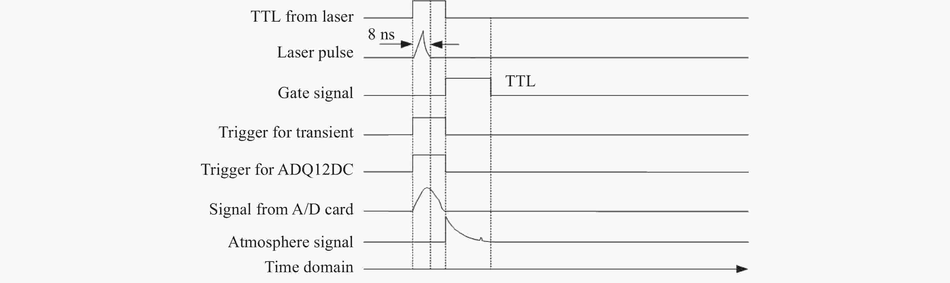
图 5 系统工作时序图
Figure 5. System working sequence diagram
-
法布里-珀罗标准具是具有重要科研价值的光学仪器,广泛应用于光学鉴频。该系统采用三通道法布里-珀罗标准具,它具有两个相同大小的边缘通道和一个锁定通道,两个边缘通道的直径为38 mm,锁定通道的直径为19 mm。边缘通道用于大气回波信号频率的测量,锁定通道用于出射激光的锁定和测量,再利用回波信号频率和出射激光频率的差值得到多普勒频移量。
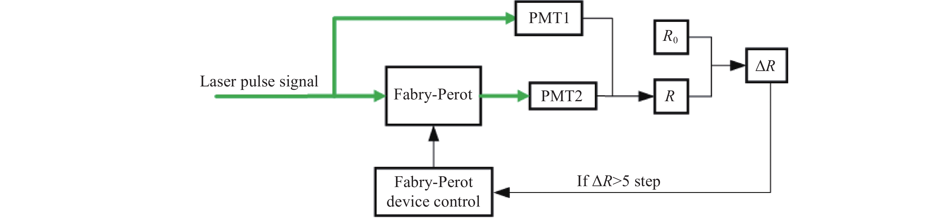
根据图1所示的测风原理,出射激光的频率位于两边缘通道的交叉点处。但是系统在实际运行过程中由于受到温度和振动的影响,使出射激光的频率发生漂移,进而导致出射激光的频率偏离交叉点位置,从而使风速测量灵敏度下降,进而导致风速测量精度下降。根据位置进行判断,若偏离锁定点的位置,则需要调整法布里-珀罗标准具的腔长,实现频率的跟踪。
出射激光频率发生漂移主要包含两部分:一部分是由于种子激光器受到温度影响,使得主激光器中的谐振腔在种子光注入时频率不匹配,从而造成频率漂移;另一部分是由于温度变化使法布里-珀罗标准具的腔长发生微小变化,从而导致频率的抖动和漂移。在系统运行时,特别是秋冬季节,昼夜温差变化大,尽管种子激光器和主激光器均配备了温控系统,但是出射激光仍有部分漂移。
图6为基于法布里-珀罗标准具的频率跟踪单元流程图。首先扫描出法布里-珀罗标准具的透过率曲线,对其进行标定,将激光器出射激光频率锁定在法布里-珀罗标准具双边缘通道的初始频谱交叉点处。根据锁定通道的透过率,按照选定的一段曲线进行多项式拟合,得到频率跟踪常数,即为法布里-珀罗标准具需要调整的位置。根据该位置调整法布里-珀罗标准具的腔长,将出射激光频率锁定在法布里-珀罗标准具双边缘通道的频谱交叉点处,使边缘通道交叉点跟踪激光频率。
图7为2022年2月21日22:20~00:50时间段内频率跟踪的结果。图7(a)为锁定通道的比值变化,图7(b)为频率跟踪的最终结果。从图中可以看出,跟踪频率范围在±50 MHz以内,因此可以大大减小频率漂移带来的风速误差。

图 6 基于法布里-珀罗标准具的频率跟踪单元流程图
Figure 6. Flow chart of frequency tracking unit based on Fabry-Perot etalon

图 7 频率跟踪结果
Figure 7. Results of tracking frequency
-
为了验证系统的探测性能,在白天和夜晚对对流层和平流层多普勒测风激光雷达系统进行探测,图8(a)为2021年12月28日15:14的水平风向和风速测量结果,图8(b)为2021年12月30日21:05的水平风向和风速测量结果。从图中可以看出,根据最高高度风速随机误差不大于5 m/s的条件,在晴朗天气下,白天的探测高度为25 km左右,夜晚的探测高度为38 km左右。
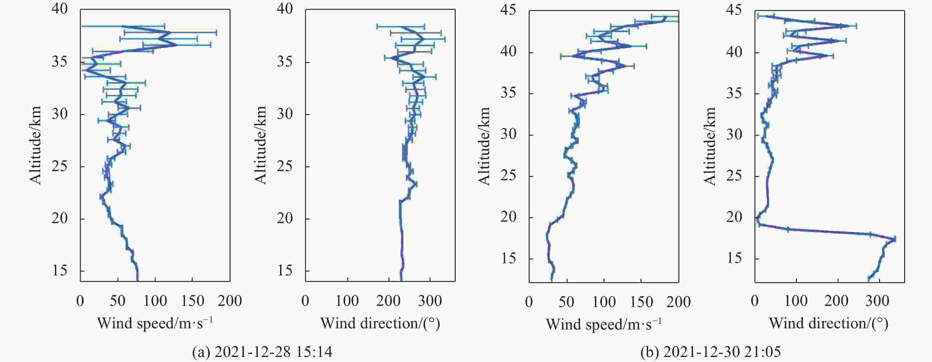
图 8 白天(a)和夜晚(b)探测的风速和风向
Figure 8. Wind speed and direction detected by (a) day and (b) night
图9为晴朗天气下对流层和平流层多普勒激光雷达探测风速与探空气球数据的对比廓线。激光雷达廓线为2021年12月29日22:00进行观测,探空气球释放的时间为21:23,二者相距60 m,探空气球的实际探测高度为28 km。从图中可以看出,激光雷达的探测廓线与探空气球采集的风速廓线和风向廓线变化趋势基本一致,最高探测高度为45 km左右。由于探空数据与激光雷达探测的风速数据分辨率不同,为了计算探空数据与激光雷达系统探测的误差,将探空数据进行插值计算,然后与激光雷达系统探测的风速进行比较,除去高空数据可以得到:在28 km以下、与探空气球重合的区域内,风速误差均小于10 m/s,其中风速误差在±5 m/s范围内的数据量约占75.8%,探测的风向与探空气球的趋势基本一致,误差范围在10°~20°之间风向误差,在15°范围内的数据量约占58.6%。

图 9 2021年12月29日风场廓线与探空气球对比廓线
Figure 9. Wind field profile and sounding balloon comparison profile on December 29, 2021
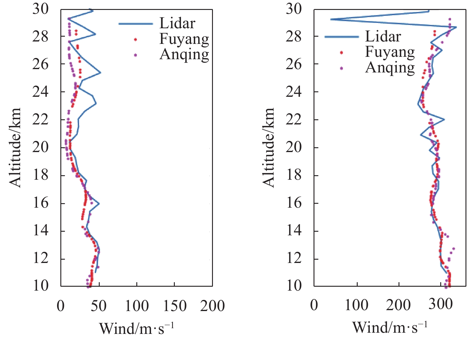
图10为2022年3月7日不同地区的探空廓线与激光雷达探测数据对比,蓝色线为激光雷达探测廓线,两条探空廓线分别为阜阳和安庆地区探空廓线,二者距离合肥分别为168.1 km和152.2 km。从图中可以看出,尽管所隔距离较远,激光雷达所测得的风速廓线与二者之间的探空数据变化趋势一致,风向也与探空廓线基本相同,说明在同一时间段内,对流层和平流层之间的大气的变化趋势相同。

图 10 不同地区的探空廓线与激光雷达数据探测对比
Figure 10. Comparison of sounding profile and lidar data detection in different regions
-
为了准确获取对流层和平流层大气风场的数据,搭建了一台多普勒直接测风激光雷达系统,采用转台式探测结构对径向风速进行探测,并使用频率跟踪的手段,保证探测精度。实测结果显示,出射激光的最大偏移量在50 MHz以内,可以大大减小风速的测量误差。最终实验结果表明,该激光雷达白天探测高度为25 km,夜晚探测高度为38 km。在28 km以下、与探空气球重合的区域内,风速误差均小于10 m/s,风向与探空气球的趋势基本一致,满足系统的设计要求。将所测的数据与安庆和阜阳的探空廓线进行对比,激光雷达所测得的风速廓线和风向廓线与二者之间的探空数据变化趋势一致,说明在同一时间段内,对流层和平流层之间大气的变化趋势相同,为研究不同地区的对流层和平流层之间的大气风场提供参考。
Frequency tracking technology of direct wind lidar and observation of atmospheric wind field in troposphere and stratosphere
-
摘要: 为了实现高精度连续探测对流层和平流层大气风场,搭建了一台直接测风激光雷达系统对对流层和平流层大气风场进行探测。该系统基于双边缘法布里-珀罗标准具的瑞利散射多普勒测风原理,使用转台式探测结构,通过频率跟踪的手段对频率漂移进行跟踪,确保测风的精度。实验结果表明,该系统对对流层和平流层大气风场探测效果良好,频率跟踪的范围为±50 MHz,可以大大减小频率漂移带来的风速误差。经过系统的稳定运行和长时间的观测,在40 km处测得的径向风速随机误差为8 m/s。径向风速合成为水平风速后,随机误差在38 km处最大为10 m/s左右。该系统白天探测高度为25 km,夜晚探测高度为38 km。与探空数据对比,风速误差均小于10 m/s,其中风速误差在±5 m/s的范围内的数据量约占75.8%,探测的风向误差与探空气球的趋势基本一致,误差范围在10°~20°之间,在15°范围内的数据量约占58.6%。将实测数据与探空数据进行统计分析,结果具有良好的一致性。该系统可以为对流层和平流层大气风场的探测提供数据支撑。Abstract: In order to continuously detect the tropospheric and stratospheric wind field with high accuracy, a direct wind lidar system is built to detect the tropospheric and stratospheric wind field. Based on the Rayleigh scattering Doppler wind measurement principle of the double edge Fabry-Perot etalon, the system uses a rotary table detection structure, and tracks the frequency drift by means of frequency tracking to ensure the accuracy of wind measurement. The experimental results show that the system has a good detection performance on the tropospheric and stratospheric atmospheric wind field, and the frequency tracking range is ±50 MHz, which can greatly reduce the wind speed error caused by frequency drift. After the stable operation of the system and long-time observation, the random error of radial wind speed measured at 40 km is 8 m/s. After the radial wind speed is combined into horizontal wind speed, the maximum random error at 38 km is about 10 m/s. The detection altitude of the system is 25 km in the daytime and 38 km at night. Compared with the sounding data, the wind speed error is less than 10 m/s, and the data volume within the range of ±5 m/s accounts for about 75.8%. The detected wind direction error is basically consistent with the trend of the sounding balloon, the error range is of 10° to 20° and the data volume within the range of 15° accounts for about 58.6%. The measured data and sounding data are statistically analyzed, and the results have good consistency. The system can provide data support for the detection of tropospheric and stratospheric atmospheric wind fields.
-
图 1 双边缘多普勒直接测风测量原理图
Figure 1. Principle diagram of double edge Doppler direct wind measurement
图 2 多普勒直接测风激光雷达系统示意图和实物图
Figure 2. Schematic diagram and physical drawing of Doppler direct wind lidar system
图 3 多普勒直接测风激光雷达系统结构示意图
Figure 3. Schematic diagram of Doppler direct wind lidar system structure
图 4 接收机光路图(a)及三维结构图(b)
Figure 4. (a) Optical path diagram and (b) three-dimensional structure diagram of receiver
图 6 基于法布里-珀罗标准具的频率跟踪单元流程图
Figure 6. Flow chart of frequency tracking unit based on Fabry-Perot etalon
图 8 白天(a)和夜晚(b)探测的风速和风向
Figure 8. Wind speed and direction detected by (a) day and (b) night
图 9 2021年12月29日风场廓线与探空气球对比廓线
Figure 9. Wind field profile and sounding balloon comparison profile on December 29, 2021
图 10 不同地区的探空廓线与激光雷达数据探测对比
Figure 10. Comparison of sounding profile and lidar data detection in different regions
表 1 系统探测指标
Table 1. System detection index
System parameters Value Wavelength/nm 532 Energy/mJ·pulse–1 800 Measuring range/km 5-35 Telescope diameter/mm 800 Wind velocity range/m·s–1 0-100 Wind speed detection error 1 m/s@5 km, 5 m/s@25 km Vertical resolution/m 300 Time resolution/min 20 Scanning range/(°) 360  下载: 导出CSV
-
[1] Cruten P J. The International Global Atmospheric Chemistry Project (IGAC) summary of an established project of the IGBP [R]. Germany: Max Planck Institute for Chemistry, 1991: 233-243. [2] 周秀骥, 陶善昌, 姚克亚. 高等大气物理学 [M]. 科学出版社, 1990. Zhou Xiuji, Tao Shanchang, Yao Keya. Advanced Atmospheric Physics [M]. Beijing: Science Press, 1990. (in Chinese) [3] Shen Fahua, Wang Zhongchun, Liu Chenglin, et al. Detection of atmospheric wind field by Mie scattering Doppler lidar [J]. Acta Optica Sinica, 2010, 30(6): 1537-1541. (in Chinese) [4] Shi Jiaxiang, Song Xiaoquan, Wu Songhua, et al. Doppler lidar telemetry technology for wind turbine vibration [J]. Optics Precision Engineering, 2020, 28(10): 2180-2191. (in Chinese) doi: 10.37188/OPE.20202810.2180 [5] Yuan Jinglong, Xia Haiyun, Wei Tianwen, et al. Identifying cloud, precipitation, windshear, and turbulence by deep analysis of the power spectrum of coherent Doppler wind lidar [J]. Optics Express, 2020, 28(25): 37406. [6] Chanin M L, Garnier A, Hauchecorne A, et al. A Doppler lidar for measuring winds in the middle atmosphere [J]. Geophysical Research Letters, 1989, 16(11): 1273-1276. doi: 10.1029/GL016i011p01273 [7] Gentry B M, Chen H L, Einadui F. Tropospheric wind measurements obtained with the Goddard Lidar Observatory for Winds (GLOW): Validation and performance [C]//Proceedings of SPIE , 2001, 4484: 74-81. [8] Dong Jihui, Cha Hyun-Ki, Kim Duk-Hyeon, et al. Doppler LiDAR measurement of wind in the Stratosphere [J]. Journal of the Optical Society of Korea, 2010, 14(3): 199-203. [9] Zheng Jun, Sun Dongsong, Chen Tingdi, et al. Scanning Rayleigh Doppler lidar for wind profiling based on non-polarized beam splitter cube optically contacted FPI [J]. Current Optics and Photonics, 2018, 2(2): 195-202. [10] Shen Fahua, Shu Zhifeng, Sun Dongsong, et al. Rayleigh scattering Doppler lidar wind field inversion method [J]. Journal of Physics, 2011, 60(6): 192-198. (in Chinese) [11] Chen Jie, Tong Yicheng, Xiao Da, et al. Study on inversion method of atmospheric aerosol extinction backscatter ratio [J]. Chinese Optics, 2021, 14(6): 1305-1316. (in Chinese) doi: 10.37188/CO.2021-0135 [12] Li Yiyue, Hu Shuling. Turbulence spectrum decomposition of lidar using independent component analysis [J]. Optics Precision Engineering, 2020, 28(5): 1029-1037. (in Chinese) [13] Yang Bin, Mo Zusi, Liu Haijiao, et al. Research on abrupt signal processing method of atmospheric detection lidar (Invited) [J]. Infrared and Laser Engineering, 2022, 51(1): 20211117. (in Chinese) [14] Zhuang Peng, Shen Fahua, Wang Bangxin, et al. Study on Rayleigh meter scattering wind lidar based on Fabry-Perot interferometer [J]. Chinese Journal of Lasers, 2020, 47(12): 1210001. (in Chinese) -

 点击查看大图

计量
- 文章访问数: 194
- HTML全文浏览量: 51
- PDF下载量: 62
- 被引次数: 0


