


-
变截面薄壁空心弯扭结构件在航空航天、机械、船舶等领域具有广泛应用,如螺旋桨结构、汽轮机中的空心叶片等[1],该类零件一般具有扭曲悬垂、截面自由变化等特征,它的型面为进行弯扭的变截面,属于较为复杂的自由曲面,生产应用中对其几何精度要求高。传统上多以数控铣削、精密铸造、特种加工等加工方式为主[2],但这些加工方式存在材料利用率低、生产周期长和加工成本高等问题,且在某些场合下无法达到实际使用要求。激光熔化沉积(laser melting deposition, LMD)技术是一种新型的快速成形技术[3-4],具有成形零件结构复杂、无模具近净成形、工艺制程简单等优点。文中基于光内送粉LMD技术,对变截面薄壁空心弯扭结构件的激光熔化沉积展开研究。
王聪[5]等建立了高度工艺参数模型,将熔覆层的截面形状与工艺参数对应,成形了具有大扭转角的薄壁件。Rajeev Dwivedi等[6]基于人工智能直接从模型制造结构件,实现了激光成形的自动化,成形得到简单的扭曲叶轮。石龙飞等[7]采用激光近净成形技术,使用特制的软件分析得到成形路径的程序,成形了单个三元叶片,但表面阶梯效应明显。石拓等[8]采用法向分层方法,利用喷头连续变姿态,成形了倾斜角从0°逐渐变化至81°的悬垂薄壁件。王明雨等[9]基于法向分层提出随形离散分层法,解决了具有截面多方向扭曲的结构件的成形路径规划问题,实现了多元扭曲结构件的堆积。
目前,国内外对变截面弯扭结构件的成形多以等截面扭转为主,而对于在空间中变截面且发生弯扭的结构件鲜有报道。变截面薄壁空心弯扭结构件在空间呈现三维扭曲状,具有扭曲悬垂、截面自由变化等特征,文中基于光内送粉LMD技术,提出空间轨迹单元离散分层法完成成形轨迹规划,空间变姿态基点偏移补偿技术对实际姿态变化基点的位置偏移进行补偿,最终实现了变截面弯扭结构件的LMD成形并有效控制了尺寸误差。
-
实验基板采用304不锈钢,经砂纸打磨、无水乙醇清洗等预处理后进行实验,其化学成分及其含量如表1所示。
表 1 304不锈钢的化学成分及其含量(质量分数,wt.%)
Table 1. Chemical compositions and content of 304 stain-less steel (mass fraction,wt.%)
Composition C Mn P S Si Cr Ni N Fe Content 0.07 2.00 0.05 0.03 0.08 17.50-19.50 8.00-10.50 0.10 Bal. 成形材料选用Fe314金属粉末,粉末粒度为50~119 μm,其化学成分及其含量如表2所示。
表 2 Fe314合金粉末的化学成分及其含量(质量分数,wt.%)
Table 2. Chemical compositions and content of Fe314 alloy powder(mass fraction,wt.%)
Composition C Si Ni Cr B Fe Content 0.1 1.0 1.0 15.0 1.0 Bal. -
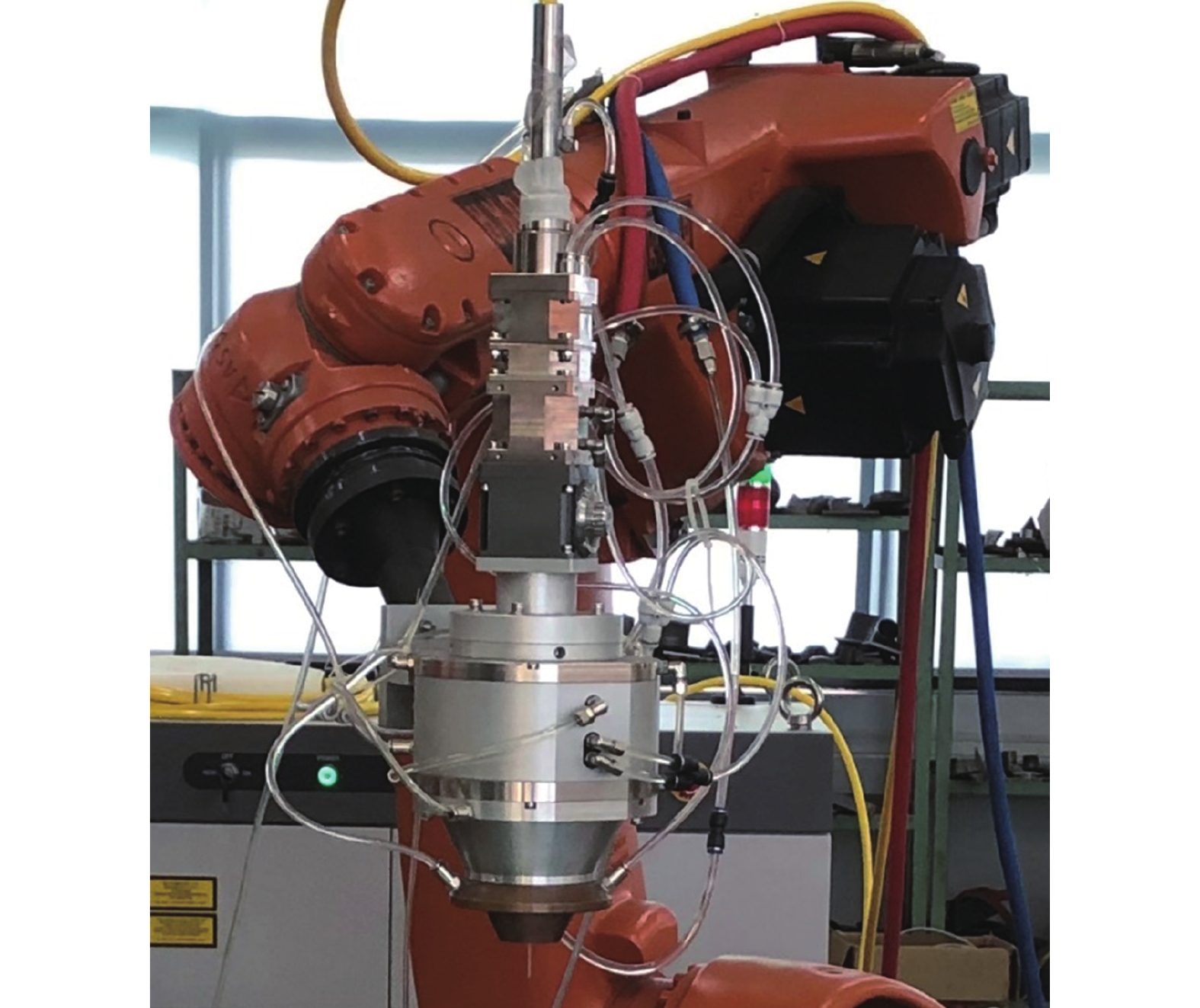
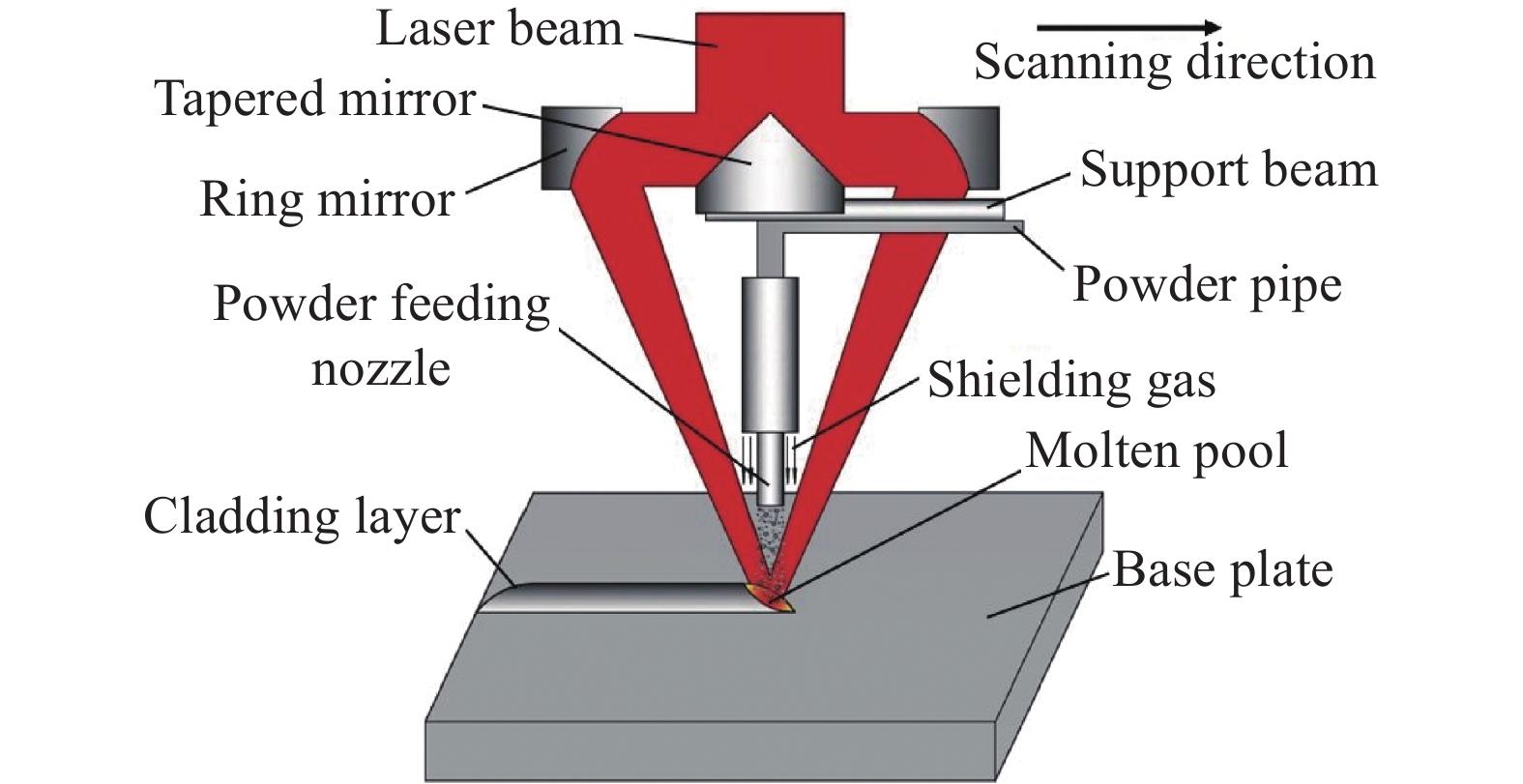
实验采用德国GTV公司的GTV PF2/2型送粉器、中空环形光内送粉熔覆喷头、锐科RFL-C6000W激光器,运动装置由六轴KUKA机械手臂和附加旋转工作台组成,所用载粉气和保护气皆为氮气。其中,中空环形光内送粉喷头为实验室自主研发[10],其原理如图1所示,采用圆锥镜和环形剖面镜将实心光束转化为中空环形光束,送粉管位于熔覆喷头(图2)中轴线上,与激光束同轴,准直保护气包裹送粉管[11-12]。载气、准直气和保护气的共同作用极大减小了重力对粉末颗粒运动轨迹的影响,使光内送粉激光熔覆喷头具有优异的集束性,光粉气达到精准耦合。因此,相比于传统的光外送粉熔覆,光内送粉不仅提高了粉末利用率且可实现在空间任意角度的熔覆,能够满足文中实验变截面薄壁空心弯扭结构件的成形需求。

图 1 中空环形光内送粉原理图
Figure 1. Principle diagram of hollow ring power feeding in laser
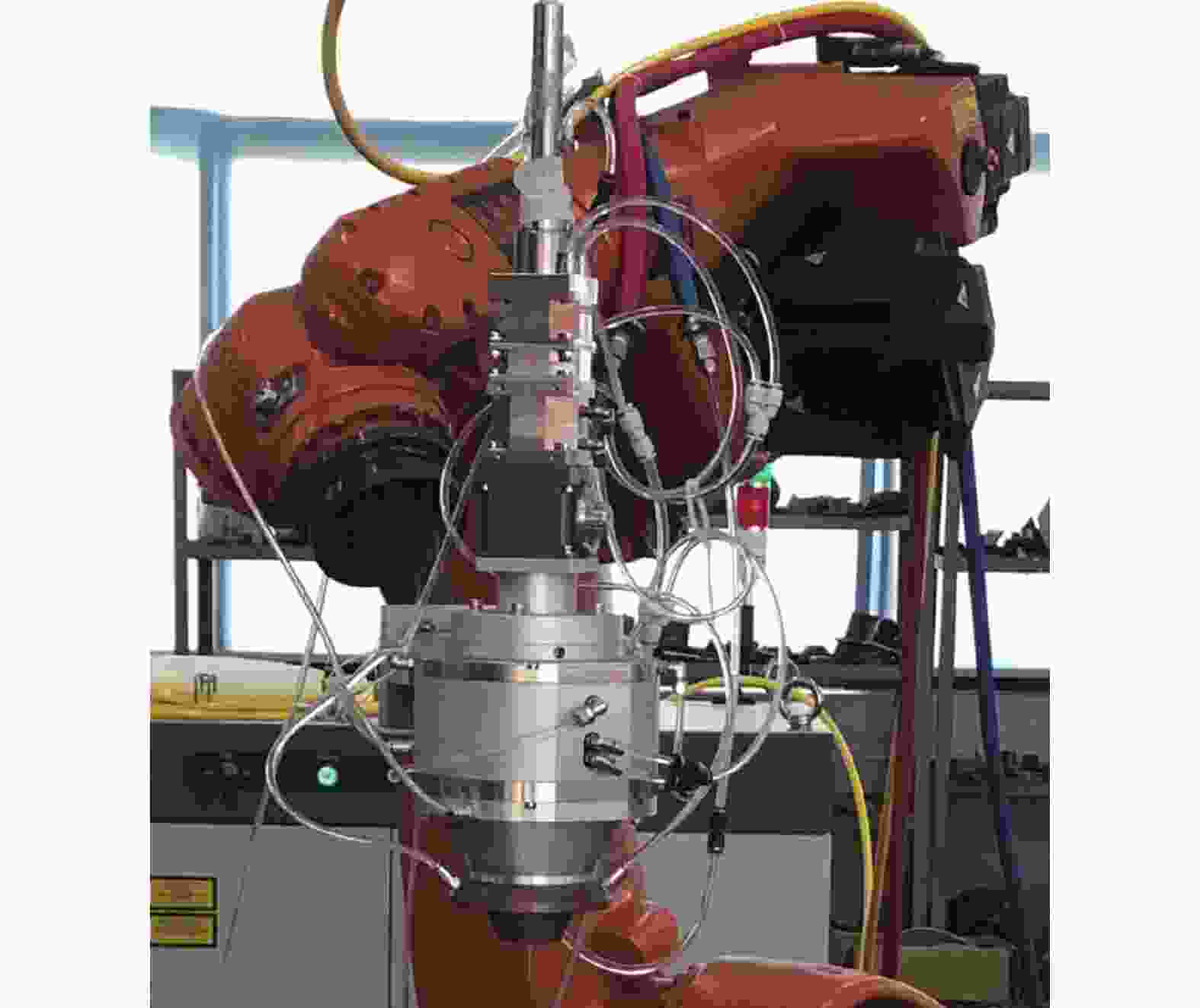
图 2 光内送粉熔覆喷头实物图
Figure 2. Physical drawing of powder feeding cladding nozzle in laser
-
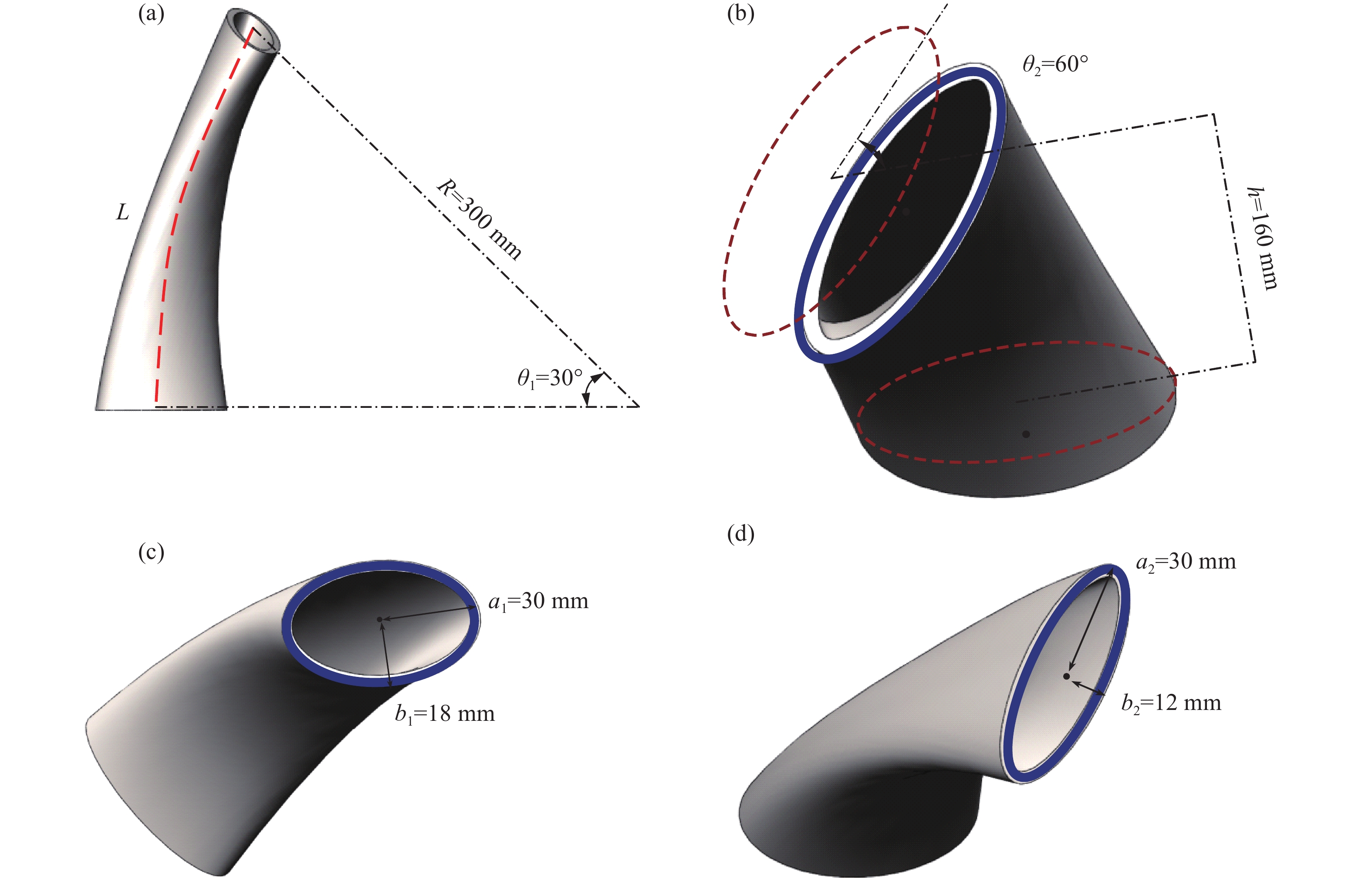
实验基于汽轮机的空心叶片,设计堆积一个变截面薄壁空心弯扭结构件,其模型图如图3所示,由结构件的形状特点可知,它具有大角度扭曲悬垂、截面变化等特征,型面为进行弯扭的变截面。该结构件横截面的中心线L为一道半径R=30 mm,圆心角θ1=30°的弧线,即截面具有弯曲的特征,上下端面存在相对扭转角θ2=60°,即截面具有扭转的特征,上下端面为尺寸不同的椭圆形,即截面具有不断变化的特征,整体壁厚为6 mm。该结构件是一个以尺寸不断变化的椭圆为截面,并伴随着截面间的相对扭转,且以中心线弧线为弯曲生长路径,完成成形的变截面薄壁空心弯扭结构件。

图 3 结构件几何模型。(a)轴测图;(b)端面扭转示意图;(c)底端面;(d)顶端面
Figure 3. Geometric model of frame member. (a) Axonometric drawing; (b) Schematic diagram of end face torsion; (c) Bottom end face; (d) Top end face
-
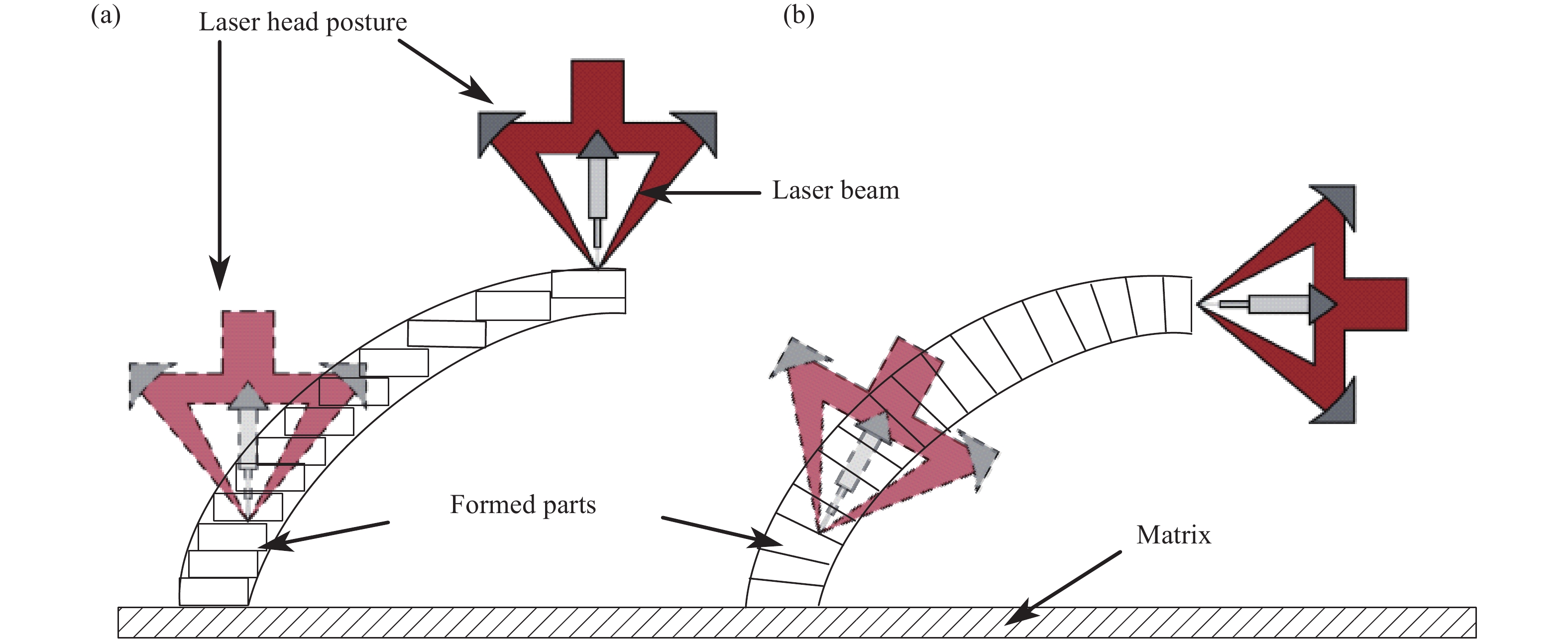
在传统的激光熔化沉积成形过程中,喷头一般保持竖直状态在水平面上进行运动,但是此方法仅适用于成形无悬垂特征的结构件,在成形有悬垂特征的结构件时,见图3(a),随着角度的增大,层与层之间的错位会发生累积,最终导致 “漏光”,无法完成成形且已成形表面粗糙度较大。
苏州大学石拓等[8]提出法向分层方法,如图4(b)所示,对结构件沿着形状轮廓进行法向分层,喷头轴线始终与基体表面轴线方向一致,并不断跟随变化,该方法使得相邻沉积层间没有错位,有效解决了使用水平分层法带来的因错位分层引起的台阶效应,提高了结构件的表面精度,且能够成形一些较为简单的悬垂结构和倾斜面。
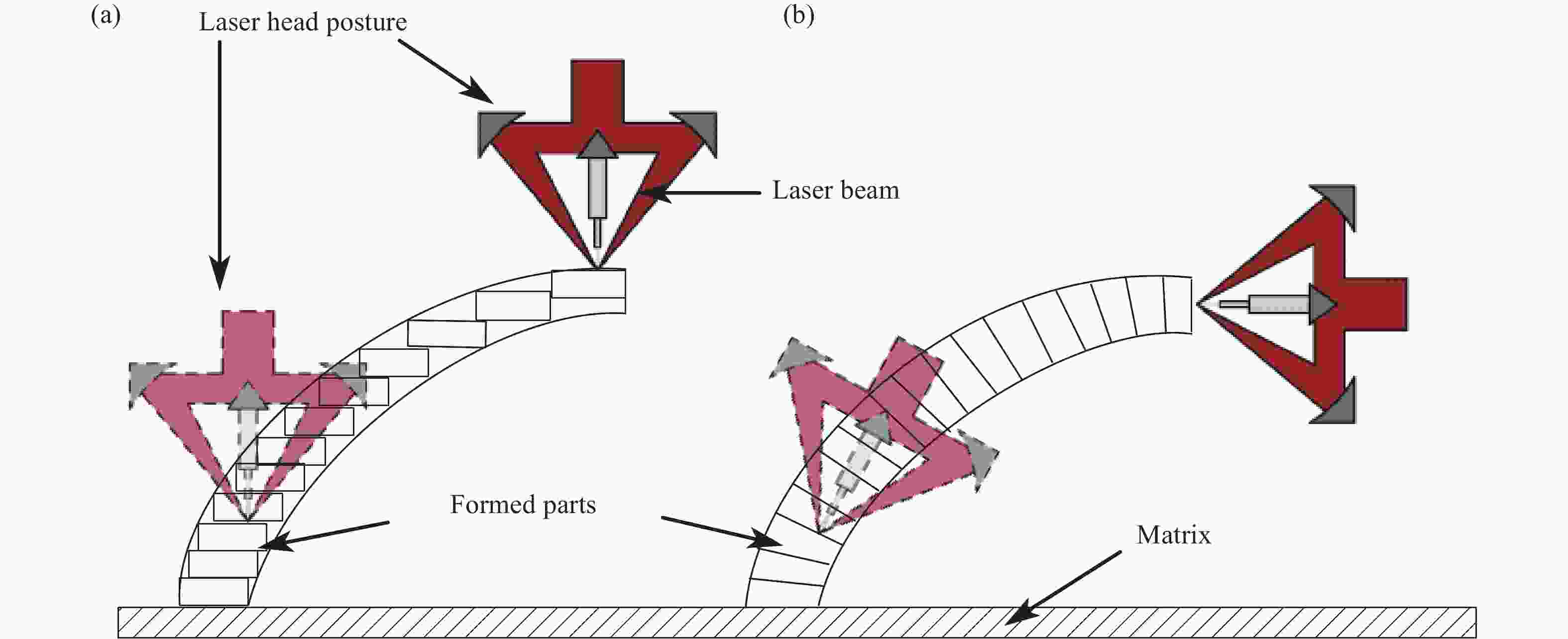
图 4 不同方式激光熔化沉积示意图。(a)水平分层示意图;(b)法向分层示意图
Figure 4. Schematic diagram of laser melting deposition with different ways. (a) Diagram of horizontal layers; (b) Diagram of normal layers
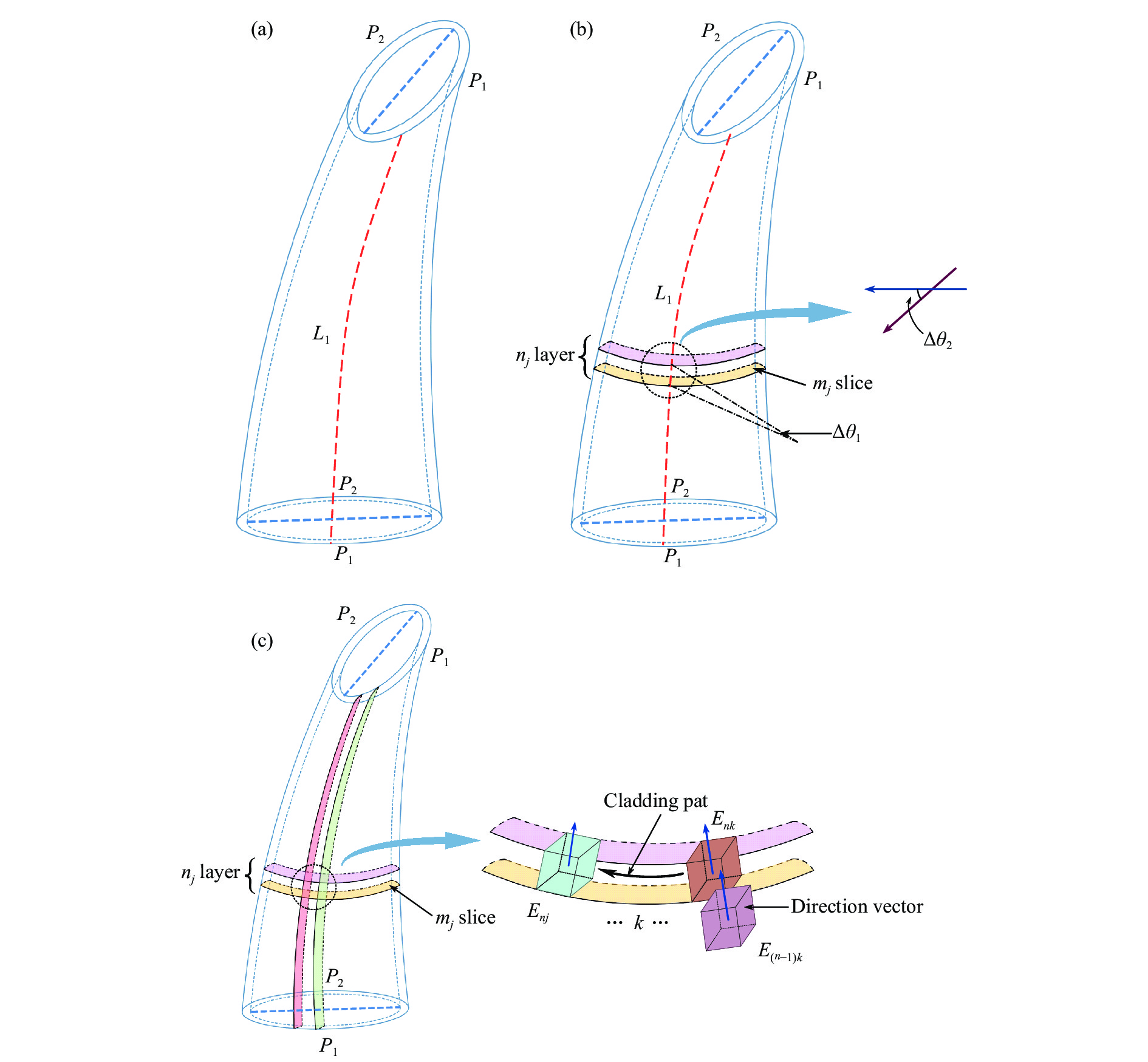
变截面弯扭结构件在空间呈现三维扭曲状,具有大角度扭曲悬垂、截面变化等特征,截面的形状随弯曲的中心弧线L连续渐变,如图5所示。为了实现该结构件的成形,文中基于上述分析的法向分层原理,提出空间轨迹单元离散分层法对该变截面弯扭结构件进行分层,其具体步骤如下:

图 5 结构件分层方法。(a)将结构件划分为两部分;(b) 获取切片层;(c)离散沉积单元
Figure 5. Method of layering frame members. (a) The structural member is divided into two parts; (b) Getting slice layer; (c) Discreting sedimentary unit
(1) 如图5(a)所示,以截面椭圆为基准,根据该结构件的形状特点,将结构件分为P1和P2两个部分进行分层,即以椭圆端点为始末点将截面等弧长分割成相同的两个部分,且两端面对应的弧的端点在无弯扭变化时的垂直投影是重合的;
(2) 如图5(b)所示,取P1部分的中心弧线L1,沿L1作法向切片得切片mj,沿L1纵向作等圆心角分割并相对扭转得切片层nj,相邻切片之间的弯曲角为Δθ1,相对扭转角为Δθ2;
(3) 如图5(c)所示,对步骤(2)所得切片沿沉积轨迹进行空间轨迹单元离散分层,得具有不同方位特征的离散沉积单元Enk,用各部分离散单元上下底面的中心连线来表示该离散沉积单元的方向向量,向量的长度为该单元的高度,向量的倾角为该单元的倾角。离散单元在同一熔覆层内高度保持一致,在相邻沉积层之间的离散单元En(k−1)和Enk呈错位分布,各离散单元的倾角成等角度线性变化,将层内离散单元横向拼接即为该段边线的喷头沉积的实际路径,纵向拼接为层间结构件的生长方向,与整个结构件的中心弧线L的切线方向是一致的;
(4) 对P2重复前两个步骤,并进行封闭拼接,拼接点即为椭圆截面的分割点。变截面弯扭结构件具有扭转和悬垂的特征,因此相邻切片层的内外侧的高度不同,分层得到的离散沉积单元的高度也不同,将相邻切片层按等圆心角拼接便能够得到整个结构件的分层信息。
根据空间轨迹单元离散分层法的原理可知,获得和计算每个离散沉积单元的位置和方向信息,便可获得喷头进行沉积时环形光斑的运动轨迹,按设计的路径完成每个离散沉积单元的沉积,即可完成对整个结构件的沉积。
如图6所示,在结构件的沉积过程中,喷头的环形光斑所在的工具坐标系相对于基体所在的基坐标系发生平移和旋转。以变截面弯扭结构件的中心轴线L与基板的交点为原点建立基面坐标系C1,其x轴与喷头沉积的第一层沉积的单道的方向一致,z轴垂直于基体平面,以喷头光斑中心点为原点,建立工具坐标系Ci,其初始z轴与基面坐标系的z轴重合。
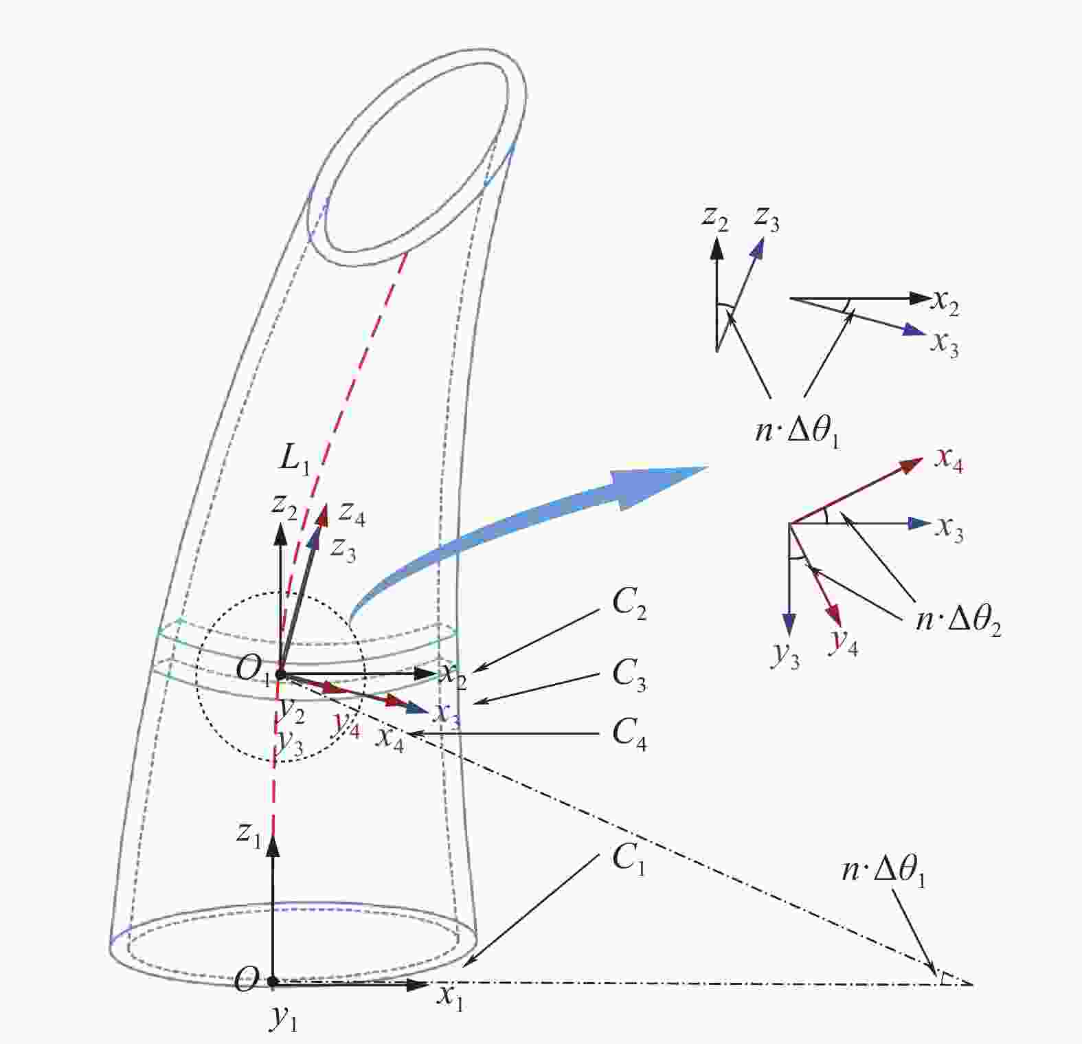
图 6 基面坐标系和工具坐标系变换过程
Figure 6. Transformation process of base coordinate system and tool coordinate system
前文通过空间轨迹单元离散分层法所得到的离散沉积单元,可视作坐标系中具有方向信息和大小信息的某点,每个离散沉积单元都有一个相对于基面坐标系C1作变换的工具坐标系Ci,Ci 相对于C1做平移变换和旋转变换,故两个坐标系间的空间位置表示关系可以用齐次变换矩阵M1n(k)表示,则在第
$n$ 层切片后,其第n层沉积层的第k个离散沉积单元的工具坐标系Cn(k)相对于基面坐标系C1作了n−1次的位置变换,此时齐次变换矩阵M1n(k)为:$$ {{\boldsymbol{M}}}_{\text{1}n}{}_{(k)}={{\boldsymbol{M}}}_{12}\cdot{{\boldsymbol{M}}}_{\text{23}}\cdots \cdot{{\boldsymbol{M}}}_{(i-1)i}=\left(\begin{array}{cc}{R}_{1n(k)}& 0\\ {T}_{1n}{}_{(k)}& 1\end{array}\right) $$ (1) 式中:T1n(k)、R1n(k)分别描述了第n层沉积层的第k个离散沉积单元的工具坐标系Cn(k)相对于基面坐标系C1所作的平移、旋转变换,由此可计算出各切片层平面相对基面坐标系的空间位置及方向信息,转化为T1n(k)、R1n(k),代入齐次变换矩阵M1n(k),控制喷头作相应的运动变换即可实现变截面弯扭结构件的成形,以P1部分为例,每层叶片的轨迹信息获取步骤如下(示意图见图6):
(1) 将工具坐标系C1沿
$\boldsymbol{O{O_1}}$ 向量平移到第n层沉积层第k个离散单元点P,得到工具坐标系C2;(2) 将工具坐标系C2绕着自身的x轴旋转n ·Δθ1度得到工具坐标系C3,此时工具坐标系C3的z轴与中心线L1在点P处的切线共线,其中Δθ1为每层沉积层对应的旋转角度,记α=n ·Δθ1;
(3) 将C3坐标系绕着自身的z轴旋转n ·Δθ1个扭转角得到工具坐标系C4,此时C4坐标系的x轴即为光斑的运动方向,其中Δθ2为每层沉积层对应的旋转角度,记β=n ·Δθ1。
P2部分同样如此,结合后得出,该弯扭结构件在第n层沉积层第k个单元的工具坐标系Cn(k)相对于基面坐标系C1的齐次变换矩阵为:
$$ {{\boldsymbol{M}}}_{{1n}{(k)}}={{\boldsymbol{M}}}_{12}\cdot{{\boldsymbol{M}}}_{23}\cdot{{\boldsymbol{M}}}_{34} $$ (2) 式中:
$$ \begin{split} &{{\boldsymbol{M}}_{12}} = \left( {\begin{array}{*{20}{c}} 1&0&0&{{T_x}} \\ 0&1&0&{{T_y}} \\ 0&0&1&{{T_z}} \\ 0&0&0&1 \end{array}} \right),{{\boldsymbol{M}}_{23}} = \left( {\begin{array}{*{20}{c}} 1&0&0&0 \\ 0&{\cos \alpha }&{\sin \alpha }&0 \\ 0&{ - \sin \alpha }&{\cos \alpha }&0 \\ 0&0&0&1 \end{array}} \right),\\ &{{\boldsymbol{M}}_{34}} = \left( {\begin{array}{*{20}{c}} {\cos \beta }&{\sin \beta }&0&0 \\ { - \sin \beta }&{\cos \beta }&0&0 \\ 0&0&1&0 \\ 0&0&0&1 \end{array}} \right), \end{split}$$ 其中
$\left( {\begin{array}{*{20}{c}} {{T_x}} \\ {{T_y}} \\ {{T_z}} \end{array}} \right) = \left( {\begin{array}{*{20}{c}} 0 \\ {R\; \cdot \;(1 - \cos \alpha )} \\ {R\; \cdot \;\sin \alpha } \end{array}} \right)$ 。据上,得到所有切片层内的每个离散沉积单元的T1n(k)和R1n(k),即可得到喷头的平移和旋转变换信息,由公式(2)计算出工具坐标系Cn(k)相对于基面坐标系C1的齐次变换矩阵M1n(k),获得喷头在进行工作时运动的位置和方向信息,即空间运动轨迹信息,喷头按照轨迹信息在离散单元之间均匀过渡,完成每层沉积层的沉积,直至完成整个变截面弯扭结构件的成形。
-
采用空间轨迹单元离散分层法进行变截面弯扭结构件的分层和沉积成形的过程中, KUKA机械臂需要不断地变化自身所处的姿态以适应变截面弯扭结构件的形状特点,该姿态信息包括结构件成形时的扫描路径信息和喷头在工作时的姿态信息[13-14]。
结构件成形时的扫描路径信息由2.2节提出的空间轨迹单元离散分层法可以获得,而喷头在工作时的姿态是由KUKA机械臂进行控制的, KUKA机械臂采用了一种路径角度连续变化过渡的方法,采用多段变角度直线进行拟合得到曲线,实际运动路径直线的角度不断发生变化,每段直线对应喷头的一个变化角度,将这些直线进行拟合,便能得到喷头在工作时的姿态信息。
如图7所示,在成形一个半径为R弧面时,以α为单位角度将圆弧等分成数段,用每等分段的弦来拟合圆弧,每段弦长为L。如图可知,每段弦长L越小,α的数目越多,值越小,拟合所得到的弧的误差越小。当α较小时,可以近似圆弧ι为:

图 7 喷头曲线运动路径拟合示意图
Figure 7. Schematic diagram of curve motion path fitting of nozzle
$$ \iota \approx L = 2R \cdot \sin \left( {\alpha /2} \right) $$ (3) 由于变截面弯扭结构件具有大角度的弯曲和扭转的特征,喷头在进行该结构件的分层和沉积过程中,其姿态也需进行如此的角度变化。文中实验的喷头的角度变化是通过KUKA机械臂绕坐标基点(工具坐标系原点)进行旋转来实现的,该基点即为姿态变换基点。实验要求喷头进行姿态变化后,激光的光斑直径需要与已成形的沉积层保持一致,否则便会出现错位而造成阶梯状的凸点,导致成形所得结构件的表面粗糙度变大,长期积累甚至出现“漏光”导致沉积终止。
每层的姿态变化基点应该是固定的,通常为某一固定离焦量的位置,但在成形过程中,随着沉积层数及截面弯扭角度的增加,结构件截面的尺寸发生明显变化,KUKA机械臂采用的线段单元拟合的方式实现光滑曲线运动使得喷头姿态变化基点的位置产生误差[15],所成形的沉积层的高度和喷头的提升量不适应,导致实际离焦量与设定的离焦量有误差,但机械臂在沉积的过程中无法自动判断激光光斑的位置并进行调整,导致出现成形误差。
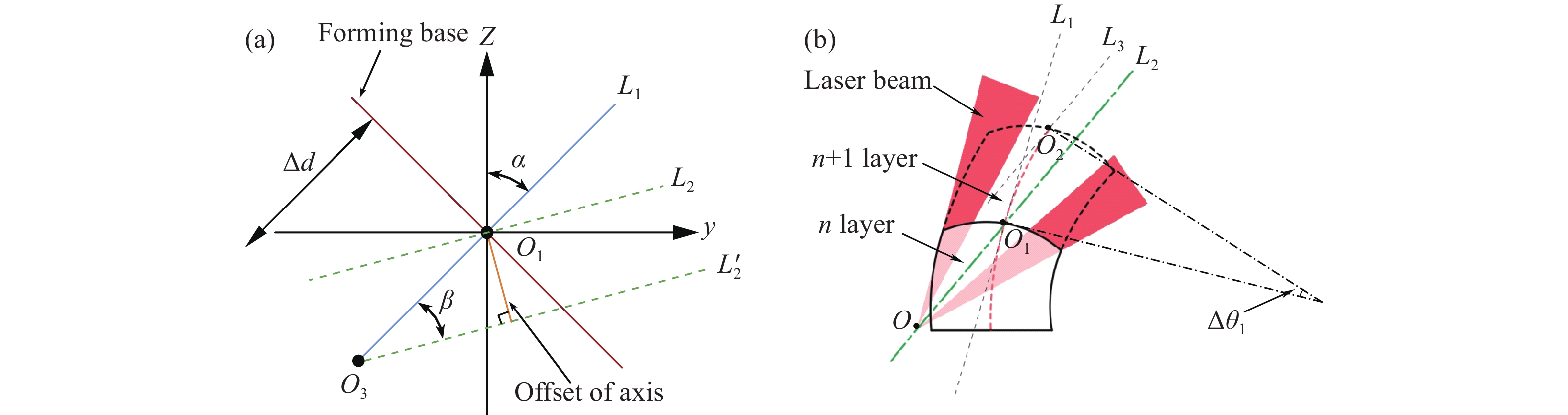
如图8(a)所示,喷头在沉积完第n层后,需要变化角度进行第n+1层的沉积,但由于上述问题,在沉积完n层后,误差累积导致本应在O1处的姿态变化基点偏移至O3喷头的光束轴线由L1旋转至L2处,如图8(b)所示,喷头的光斑不能完成全覆盖第n层沉积层,导致层间沉积层出现错位而造成阶梯状的凸点,因此,需要计算O1和O3间的相对位置,在喷头光束轴线进行旋转前对姿态变化基点的位置进行补偿。

图 8 补偿前喷头光斑位置示意图。(a)完成第n层沉积;(b)姿态变化基点偏移
Figure 8. Schematic diagram of nozzle spot position before compensation. (a) Completing the deposition of the nth layer; (b) Attitude change base point offset
计算O1和O3间的相对位置,示意图见图9(a),喷头的初始光束轴线L1与竖直方向夹角为α,L1变化至L2处的角度变化为β,理论姿态变化基点O1与实际姿态变化基点O3间的距离为Δd,即姿态变化基点的偏移量,将该偏移量沿y轴和z轴方向进行分解,通过几何计算得偏移量Δy和Δz分别为:
$$ \Delta {{y = }}2\Delta d \cdot \sin \left( {\beta /2} \right) \cdot \cos \left( {\alpha + \beta /2} \right) $$ (4) $$ \Delta z{\text{ = }}2\Delta d \cdot \sin \left( {\beta /2} \right) \cdot \sin \left( {\alpha + \beta /2} \right) $$ (5) 在完成第n层的沉积后,在程序中运行公式(4)、(5)对应的变化,将实际姿态变化基点的位置调整至O1处,如图9(b)所示,即可有效地实现对喷头姿态变化基点位置的补偿,实现自动调整控制。
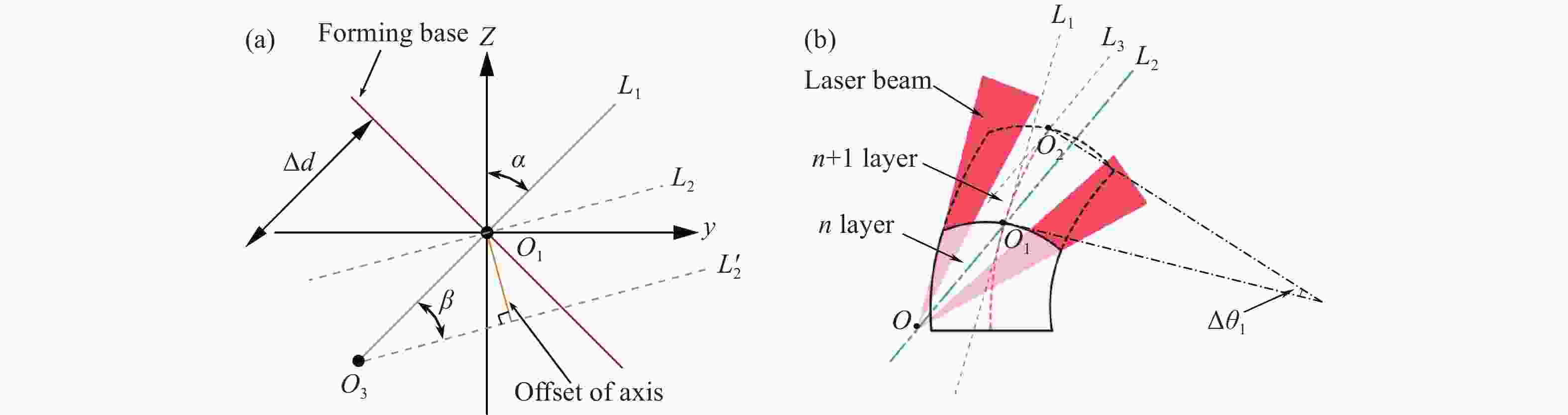
图 9 补偿调整示意图。(a) 变姿态基点偏移几何示意图;(b)补偿后喷头光斑位置示意图
Figure 9. Schematic diagram of compensation adjustment. (a) Geometric schematic diagram of variable attitude base point offset; (b) Schematic diagram of nozzle spot position after compensation
如图10(a)所示,在完成喷头姿态变化基点位置补偿和喷头姿态变化后,喷头的光束轴线由L1变化至L2,与图9(b)中第n+1层沉积层表面中心线L3平行,通过第n层沉积层表面中心点O1,保证了喷头光斑能够完全覆盖沉积的第n层沉积层表面弧
$\widehat{a O_1 c} $ ,且结构件中心线Lc上的离焦量不变。由于实验拟成形的变截面弯扭结构件具有大角度扭曲悬垂、截面变化等特征,且采用空间轨迹单元离散分层法进行分层,结构件的每一层外侧的体积大于内侧体积,见图10(a),截面面积Sabo2O1>S
cdo2O1,因此在进行沉积时,工艺上要求在完成第n层沉积,进行喷头姿态变化后,熔道生长量体积的外侧需要大于内侧。如图10(a)所示,L4是过点O1的等离焦量线,由图可知,离焦量c>O1>a,因此能量密度Ea>EO1>Ec,在送粉器送粉充足的情况下,沉积层生长量应该a>O1>c,满足熔道生长量体积的外侧需要大于内侧的工艺需求。 图10(b)所示为完成第n+1层的沉积后的状态,重复上述步骤,即可完成变截面弯扭结构件的高精度沉积。

图 10 沉积层空间变角度生长示意图。(a)沉积层生长过程;(b)完成第n+1层沉积
Figure 10. Schematic diagram of spatial variable angle growth of sedimentary layer. (a) Growth process of sedimentary layer; (b) Completing the deposition of layer n+1
-
实验基于笔者团队实验室自主研发的光内送粉沉积喷头,根据文中提出的空间轨迹单元离散分层法对结构件进行切片,将计算得到的离散沉积单元的方位特征信息赋给KUKA机械臂的计算机进行处理,使用KRL程序语言中的几何操作命令将离散单元的工具坐标系与基面坐标系相关联,最终获得该变截面弯扭结构件的成形轨迹程序,并在程序中应用文中提出的空间变姿态基点偏移补偿技术,对实际姿态变化基点的位置偏移进行补偿,提升成形精度。该多元弯扭结构件的激光熔化沉积成形过程如图11所示,其中图11(a)的成形过程由于未使用空间变姿态基点偏移补偿技术,误差不断累积,造成了“漏光”现象,最终导致成形的终止。

图 11 成形过程。(a)“漏光现象”;(b)成形过程全景图;(c)成形过程正视图;(d)成形过程侧视图
Figure 11. Forming process. (a) "Laser leakage"; (b) Panorama of forming process; (c) Front view of forming process; (d) Side view of forming process
实验过程中,将结构件分为200层进行成形[16],使用的激光初始功率为4 000 W,到第20层降低至2100 W,每层降低85 W,扫描线速度为外侧7.8 mm/s,内侧7.2 mm/s,离焦量为−8.5 mm,送粉量为45 g/min,每层的提升量Δh=0.8 mm。其中,在计算空间变姿态基点偏移补偿数据时,理论姿态变换基点O1和实际姿态变换基点O3之间的距离Δd=Δh/3,喷头的初始光束轴线L1与竖直方向夹角为α值为n·0.15°,L1变化至L2处的角度变化β为0.15°,将这些数据代入公式(4)、(5)即可得到在进行每层的沉积前需要调整的偏移量Δy和Δz的值。
-
文中提出并应用空间轨迹单元离散分层法和空间变姿态基点偏移补偿技术,分别对变截面薄壁空心弯扭结构件的成形进行轨迹规划和尺寸误差控制,故该节对沉积完成的结构件进行尺寸误差分析[17],成形所得结构件实物图如图12所示。
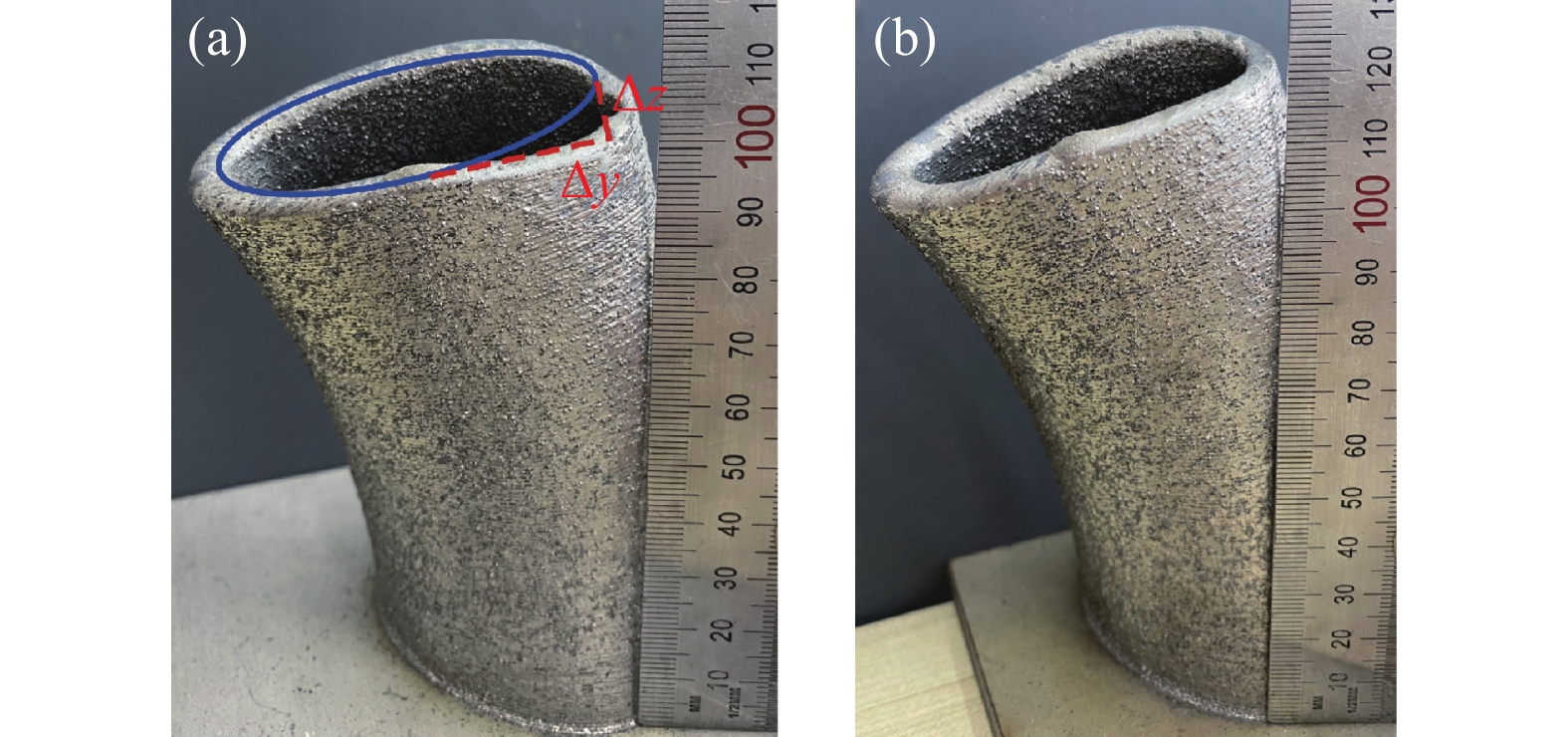
将未使用空间变姿态基点偏移补偿技术成形的结构件与使用了该技术成形的结构件进行对比,如图13(a)所示,未使用补偿技术时成形的结构件在成形过程中,喷头的实际姿态变化基点发生了偏移,随着沉积层数的增加,偏移量Δy和Δz的值累积使得成形过程中的“漏光现象”愈发严重,最终导致成形的终止,而如图13(b)所示,使用补偿技术成形的结构件尺寸误差明显减少,最终顺利完成了结构件的成形。
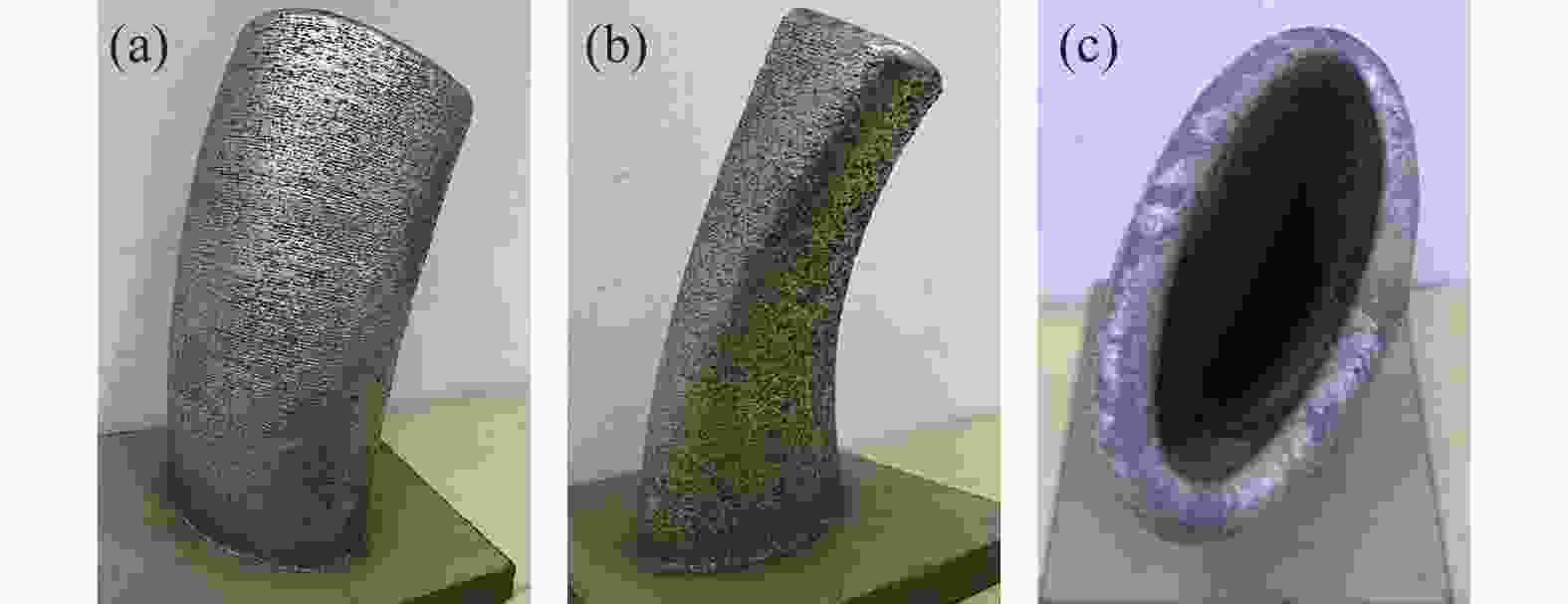
图 12 成形所得结构件实物图
Figure 12. Physical drawing of formed structural parts
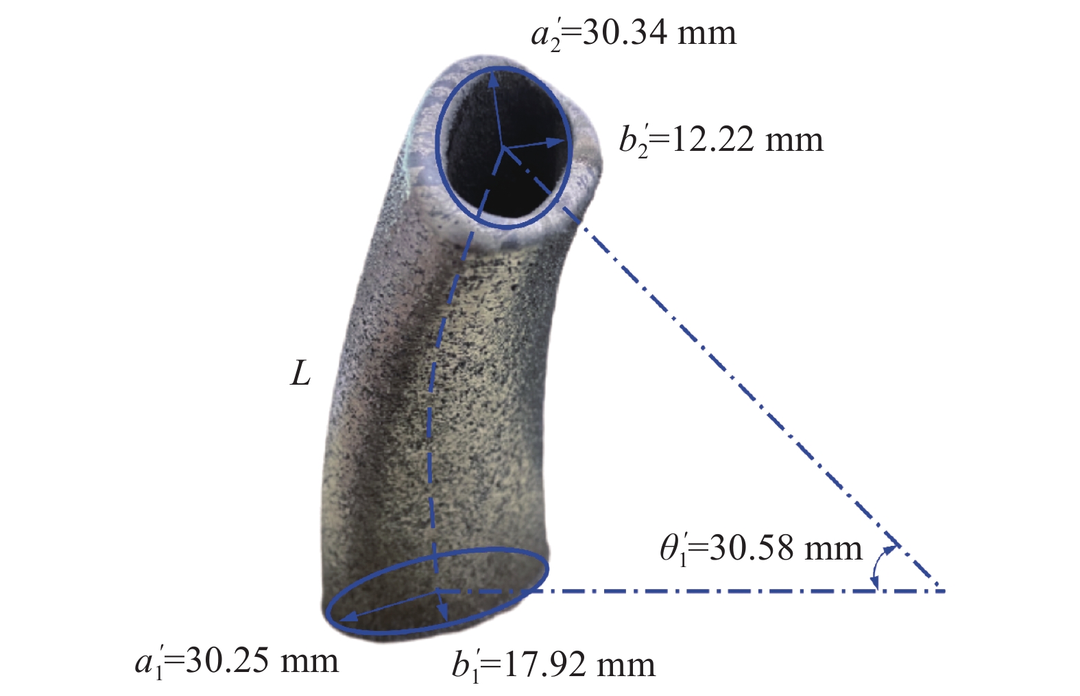
经过测量,如图14所示,沉积成形得到的结构件下端面尺寸为a'1=30.25 mm,b'1=17.92 mm,上端面尺寸为a'2=30.34 mm,b'2=12.22 mm,与设计尺寸的误差分别为0.83%、−0.44%、1.13%、1.83%;中心线L'=153.5 mm,与设计尺寸的误差为2.22%;悬垂弯曲角度θ'1=30.58°,上下端面相对扭转角θ'2=60.68°,与设计尺寸的误差分别为1.93%和1.13%。由此可见,该结构件实际成形尺寸与设计尺寸的相对误差较小,成形形貌较好,且表面平整无明显气孔或夹杂缺陷。

图 13 空间变姿态基点偏移补偿技术使用对比图。(a)未使用;(b)已使用
Figure 13. Comparison diagram of space variable attitude base point offset compensation technology. (a) Not used; (b) Used
如图15所示,对结构件的壁厚进行测量分析,分别取如图所示的四条路径a、b、c、d自下而上的10个点处的壁厚进行测量,四条路经上的壁厚分别在5.9~6.14 mm、5.95~6.17 mm、5.98~6.12 mm、5.92~6.19 mm之间,使用该工艺参数设计的单道理论值为6 mm,故该结构件的整体壁厚基本保持稳定。
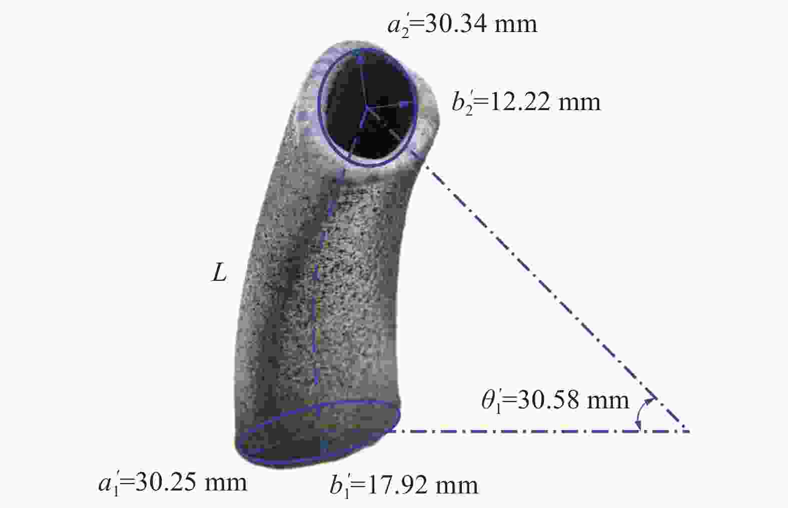
图 14 结构件实际尺寸示意图
Figure 14. Schematic diagram of actual dimensions of structural members
-
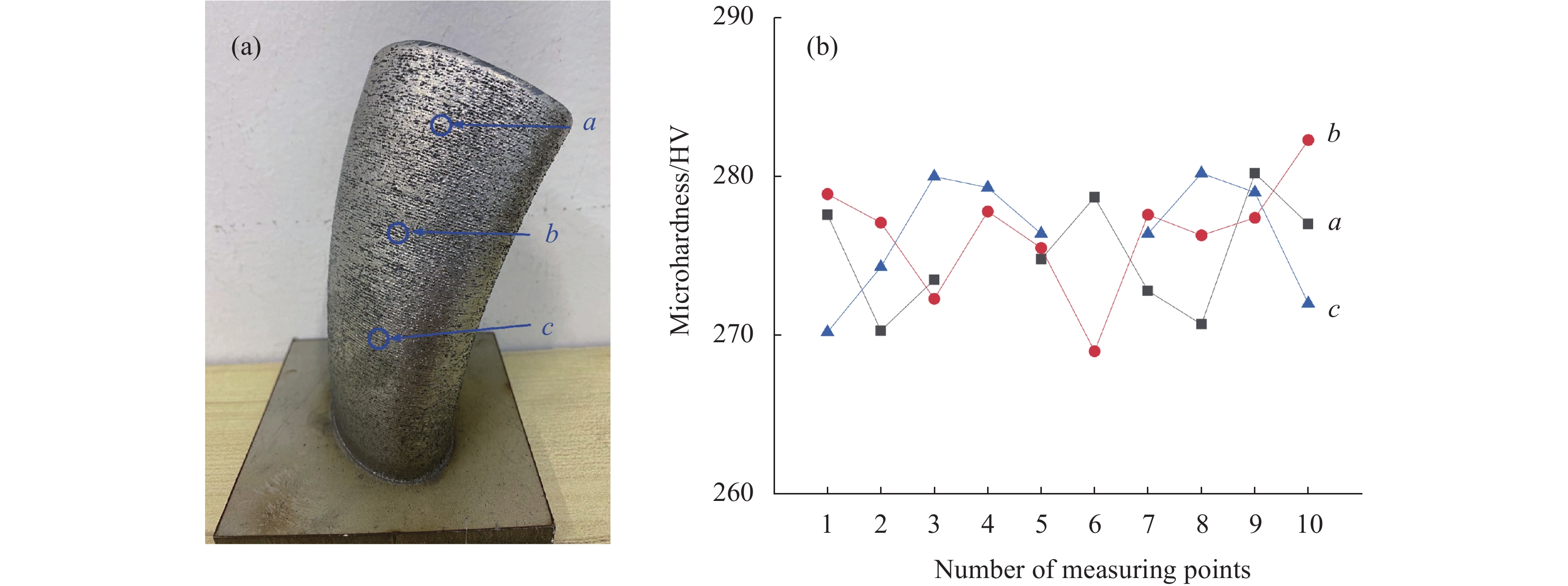
如图16所示,对该结构件的a、b、c三个位置沿着熔覆层的生长方向各选取10个测量点进行取样,采用MH-5显微硬度计进行显微硬度测量,使用菱形锥头对试样施加压力,加载载荷为500 g,保压时间为10 s,通过测量目镜中观察到的菱形压痕对角线长度计算硬度值,并用维氏硬度表示输出结果。结果如图所示,三个取样位置的显微硬度分别在270.3~280.2 HV、269~282.2 HV、272~280.2 HV之间,可见该结构件的整体显微硬度基本保持稳定,分布较为均匀。
-
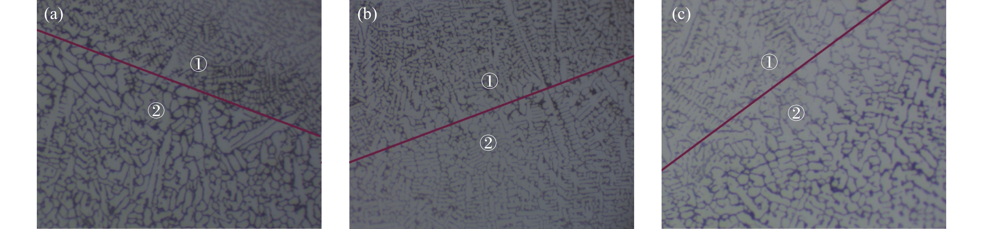
对图16所示的结构件中的a、b、c三个位置进行线切割取样,处理后得到的显微组织图如图17所示,可见该结构件内部组织致密均匀,没有明显的气孔、裂缝等缺陷。各组织部分以树枝晶为主,树枝晶的生长方向即结构件在成形时的散热方向,由于激光熔化沉积成形过程是快速熔化、快速冷却的凝固过程,极大的过冷度导致成形的晶粒细小、组织细密,从图17可以看出,区域2的组织相较于区域1明显更得粗大、疏松,这是因为在成形过程中,在沉积下一层时,当前的沉积层上表面会受到激光的二次加热,导致部分枝晶受到破坏,晶粒粗大。
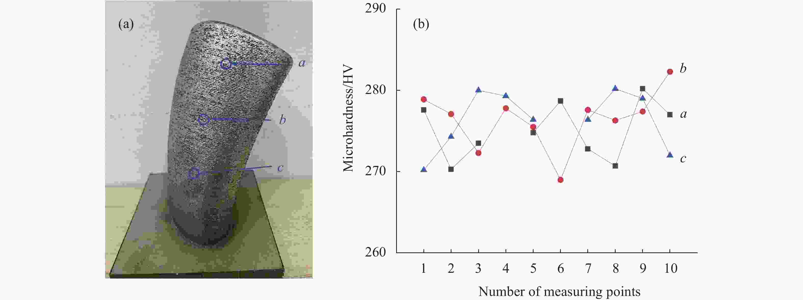
图 16 结构件显微硬度测量。(a)测量点取样示意图;(b)不同位置取样的显微硬度
Figure 16. Microhardness measurement of structural parts. (a) Sampling diagram of measuring points; (b) Microhardness of samples taken at different locations

图 15 结构件实际壁厚测量。(a)测量点取样示意图;(b)不同位置取样的壁厚
Figure 15. Actual wall thickness measurement of structural members. (a) Sampling diagram of measuring points; (b) Wall thickness sampled at different locations

图 17 显微组织图
Figure 17. Microstructure diagram
-
(1)文中提出了空间轨迹单元离散分层法,通过该方法获得离散沉积单元,以此来记录成形过程中喷头的方向和高度信息,并通过坐标系进行成形轨迹规划,解决了具有扭曲悬垂、截面自由变化等特征的变截面弯扭结构件的分层问题,实现了结构件的稳定成形。
(2)在控制程序中应用文中提出的空间变姿态基点偏移补偿技术,对喷头的实际姿态变化基点的位置偏移进行补偿,即在进行每层沉积前对偏移量Δy和Δz进行补偿调整,以保证离焦量的一致性,通过该方法有效控制成形尺寸误差,提升成形精度。
(3)成形所得结构件尺寸精度较高,形状尺寸误差在−0.44%~1.83%之间,结构件平均厚度在5.9~6.19 mm之间,结构件显微硬度在269~282.2 HV之间,结构件表面和内部皆致密均匀,无明显的气孔、裂缝等缺陷。
Research on laser melting deposition forming process and accuracy of thin-walled hollow bending and torsion structural parts with variable cross-section
-
摘要: 基于光内送粉激光熔化沉积(laser melting deposition, LMD)技术,研究变截面薄壁空心弯扭结构件的成形工艺。针对该类复杂结构件成形轨迹规划的难点,提出空间轨迹单元离散分层法对结构件进行分层并生成离散沉积单元,按设计的路径进行每个离散沉积单元的沉积。针对在实际成形过程中由于机械臂采用线段单元拟合的方式实现光滑曲线运动导致的误差,提出空间变姿态基点偏移补偿技术,对成形过程中实际姿态变化基点的位置偏移进行补偿,以此实现对尺寸误差的有效控制。最终实现变截面薄壁空心弯扭结构件的激光熔化沉积成形,成形所得结构件尺寸精度较高,形状尺寸误差在−0.44%~1.83%之间,结构件平均厚度在5.9~6.19 mm之间,结构件显微硬度在269~282.2 HV之间,结构件表面和内部皆致密均匀,无明显的气孔、裂缝等缺陷。Abstract:
Objective Variable cross-section thin-walled hollow bending and torsion structural parts have been widely used in aerospace, machinery, shipbuilding and other fields, such as propeller structure, hollow blades in steam turbines, etc. These parts generally have the characteristics of twisting and overhanging, free change of section, etc. Its profile is a variable cross-section for bending and torsion, belonging to a relatively complex free surface, which requires high geometric accuracy in production and application. Traditionally, CNC milling, precision casting, special machining and other processing methods are mainly used, but these processing methods have problems of low material utilization, long production cycle and high processing costs, and in some cases can not meet the actual use requirements. Laser melting deposition (LMD) technology is a new rapid prototyping technology, which has the advantages of complex structure of forming parts, near net forming without mold, and simple process. Based on the technology of laser melting deposition (LMD), the laser melting deposition of thin-walled hollow bending and torsion structure with variable cross-section is studied in this paper. Methods Variable cross-section thin-walled hollow bending and twisting structural parts are three-dimensionally twisted in space, with the characteristics of twisting, overhanging and free change of cross-section. Based on the technology of laser melting deposition (LMD) with optical powder feeding, this paper proposes the discrete layered method of space trajectory element to complete the forming trajectory planning (Fig.5), and proposes the compensation technology of base point offset of space variable attitude to compensate the position offset of the actual attitude change base point (Fig.10). Finally, the laser melting deposition forming of the bending and twisting structural parts with variable cross-section was realized and the dimensional error was effectively controlled. Results and Discussions In view of the difficulties of forming trajectory planning of such complex structural parts, the discrete layered method of space trajectory element is proposed to layer the structural parts and generate discrete deposition units, and each discrete deposition unit is deposited according to the designed path. In view of the error caused by the smooth curve movement of the manipulator using line segment element fitting in the actual forming process, the space variable attitude base point offset compensation technology is proposed to compensate the position offset of the actual attitude change base point in the forming process, so as to realize the effective control of the size error (Fig.13). Conclusions Through the above methods, the forming dimensional error is effectively controlled, the forming accuracy is improved, and finally the laser melting deposition forming of thin-walled hollow bending and torsion structural parts with variable cross-section is realized. The dimensional accuracy of the formed structural parts is relatively high, the shape dimensional error is between −0.44% and 1.83%, the average thickness of the structural parts is between 5.9 and 6.19 mm, the microhardness of the structural parts is between 269 and 282.2 HV, and the surface and interior of the structural parts are dense and uniform, without obvious pores, cracks and other defects. -
图 3 结构件几何模型。(a)轴测图;(b)端面扭转示意图;(c)底端面;(d)顶端面
Figure 3. Geometric model of frame member. (a) Axonometric drawing; (b) Schematic diagram of end face torsion; (c) Bottom end face; (d) Top end face
图 4 不同方式激光熔化沉积示意图。(a)水平分层示意图;(b)法向分层示意图
Figure 4. Schematic diagram of laser melting deposition with different ways. (a) Diagram of horizontal layers; (b) Diagram of normal layers
图 5 结构件分层方法。(a)将结构件划分为两部分;(b) 获取切片层;(c)离散沉积单元
Figure 5. Method of layering frame members. (a) The structural member is divided into two parts; (b) Getting slice layer; (c) Discreting sedimentary unit
图 6 基面坐标系和工具坐标系变换过程
Figure 6. Transformation process of base coordinate system and tool coordinate system
图 8 补偿前喷头光斑位置示意图。(a)完成第n层沉积;(b)姿态变化基点偏移
Figure 8. Schematic diagram of nozzle spot position before compensation. (a) Completing the deposition of the nth layer; (b) Attitude change base point offset
图 9 补偿调整示意图。(a) 变姿态基点偏移几何示意图;(b)补偿后喷头光斑位置示意图
Figure 9. Schematic diagram of compensation adjustment. (a) Geometric schematic diagram of variable attitude base point offset; (b) Schematic diagram of nozzle spot position after compensation
图 10 沉积层空间变角度生长示意图。(a)沉积层生长过程;(b)完成第n+1层沉积
Figure 10. Schematic diagram of spatial variable angle growth of sedimentary layer. (a) Growth process of sedimentary layer; (b) Completing the deposition of layer n+1
图 11 成形过程。(a)“漏光现象”;(b)成形过程全景图;(c)成形过程正视图;(d)成形过程侧视图
Figure 11. Forming process. (a) "Laser leakage"; (b) Panorama of forming process; (c) Front view of forming process; (d) Side view of forming process
图 13 空间变姿态基点偏移补偿技术使用对比图。(a)未使用;(b)已使用
Figure 13. Comparison diagram of space variable attitude base point offset compensation technology. (a) Not used; (b) Used
图 14 结构件实际尺寸示意图
Figure 14. Schematic diagram of actual dimensions of structural members
图 16 结构件显微硬度测量。(a)测量点取样示意图;(b)不同位置取样的显微硬度
Figure 16. Microhardness measurement of structural parts. (a) Sampling diagram of measuring points; (b) Microhardness of samples taken at different locations
图 15 结构件实际壁厚测量。(a)测量点取样示意图;(b)不同位置取样的壁厚
Figure 15. Actual wall thickness measurement of structural members. (a) Sampling diagram of measuring points; (b) Wall thickness sampled at different locations
表 1 304不锈钢的化学成分及其含量(质量分数,wt.%)
Table 1. Chemical compositions and content of 304 stain-less steel (mass fraction,wt.%)
Composition C Mn P S Si Cr Ni N Fe Content 0.07 2.00 0.05 0.03 0.08 17.50-19.50 8.00-10.50 0.10 Bal.  下载: 导出CSV
表 2 Fe314合金粉末的化学成分及其含量(质量分数,wt.%)
Table 2. Chemical compositions and content of Fe314 alloy powder(mass fraction,wt.%)
Composition C Si Ni Cr B Fe Content 0.1 1.0 1.0 15.0 1.0 Bal.
下载: 导出CSV
-
[1] Zhu Y W, Xu J W, Zhao J S. Forming law and experimental study of large twist integral turbine blade by electrochemical generative machining [J]. China Mechanical Engineering, 2006(17): 1778-1783. (in Chinese) doi: 10.3321/j.issn:1004-132X.2006.17.005 [2] Wei J H, Kuang Y. Research on ceramic shell technology of large complex thin wall integral investment casting [J]. Casting Technology, 2016, 37(3): 488-491. (in Chinese) doi: 10.16410/j.issn1000-8365.2016.03.024 [3] Gu D D, Zhang H M, Chen H Y, et al. Laser additive manufacturing of high-performance metallic aerospace components [J]. Chinese Journal of Lasers, 2020, 47(5): 0500002. (in Chinese) doi: 10.3788/CJL202047.0500002 [4] Huang L F, Sun Y N, Wang G J. Research progress of laser cladding high-entropy alloy coating [J]. Laser & Opto-electronics Progress, 2019, 59(24): 240003. (in Chinese) [5] Wang C, Shi S H, Fang Q Q, et al. Research on laser cladding forming of close-packed multivariant twisty thin-wall parts [J]. Chinese Journal of Lasers, 2017, 44(6): 0602004. (in Chinese) doi: 10.3788/CJL201744.0602004 [6] Rajeev Dwivedi, Radovan Kovacevic. An expert system for generation of machine inputs for laser-based multi-directional metal deposition [J]. International Journal of Machine Tools & Manufacture, 2006, 46: 1811-1822. [7] 石龙飞. 激光近净成形金属三元叶轮叶片实验研究[D]. 大连: 大连理工大学, 2016. Shi Longfei. Experimental study on laser near net shape metal three-dimensional impeller blade [D]. Dalian: Dalian University of Technology, 2016. (in Chinese) [8] Shi T, Wang Y Q, Lu B H, et al. Laser cladding forming of cantilevered thin-walled part based on hollow-laser beam inside powder feeding technology [J]. Chinese Journal of Lasers, 2015, 42(10): 1003003. (in Chinese) doi: 10.3788/CJL201542.1003003 [9] 王明雨. 基于光内送粉多元扭曲结构件激光熔覆成形研究[D]. 苏州: 苏州大学, 2021. Wang M Y. Research on laser cladding forming of multivariate twisted structural parts based on optical powder feeding [D]. Suzhou: Suzhou University, 2021. (in Chinese) [10] Yang S, Shi S H, Fu G Y, et al. Impact of hollow ring laser defocused amount on melting channel bump defect self healing effect [J]. Chinese Journal of Lasers, 2015, 42(5): 79-85. (in Chinese) [11] Wang M Y, Shi S H, Shi T, et al. Conformal discrete layering of multivariant twisted structure based on inside-laser powder feeding [J]. Chinese Journal of Lasers, 2021, 48(10): 1002114. (in Chinese) doi: 10.3788/CJL202148.1002114 [12] Wan L, Shi S, Xia Z R. Directed energy deposition of CNTs/AlSi10Mg nanocomposites: Powder preparation, temperature field, forming, and properties [J]. Optics & Laser Technology, 2021, 139: 106984. [13] Yu L L, Shi S H, Di K Y. Research on the laser cladding inclined wall accumulation based on the internal laser coaxial-powder feeding technology [J]. Laser & Infrared, 2009, 39(3): 264-266. (in Chinese) doi: 10.3969/j.issn.1001-5078.2009.03.009 [14] Yu C, Miao Q Y, Shi L F, et al. Experimental research on laser engineered net shaping of thin-walled structures with large inclination angles [J]. China Mechanical Engineering, 2020, 31(5): 595-602. (in Chinese) doi: 10.3969/j.issn.1004-132X.2020.05.012 [15] 孟伟栋. 光内送粉空间变姿态激光堆积试验研究[D]. 苏州: 苏州大学, 2015. Meng W D. Experimental study on space variable attitude laser stacking with optical powder feeding [D]. Suzhou: Soochou University, 2015. (in Chinese) [16] Pang Y F, Fu G Y, Wang M Y, et al. Parameter optimization in high deposition rate laser cladding based on response surface method and genetic neural network model [J]. Chinese Journal of Lasers, 2021, 48(6): 0602112. (in Chinese) doi: 10.3788/CJL202148.0602112 [17] Li D S, Shi T, Shi S H, et al. Laser cladding forming technology of flat-top thin-walled part based on special-shaped base surface [J]. Chinese Journal of Lasers, 2019, 46(11): 1102002. (in Chinese) doi: 10.3788/CJL201946.1102002 -

 点击查看大图
计量
- 文章访问数: 175
- HTML全文浏览量: 30
- PDF下载量: 19
- 被引次数: 0


