


-
随着航空航天技术的发展,对大推重比发动机的研制需求日益提高,对发动机的效率也提出了更高的要求。针对航天发动机而言,其主要依靠供油装置上分布的大量细小供油孔以实现高效率、高均匀性的燃油供给,这些供油孔的尺寸精度及内表面质量直接决定了燃油的流量和雾化均匀性,最终决定了发动机的燃油效率[1]。通常,这些微孔的直径为0.3~1.0 mm,深度为0.5~4 mm[2]。供油孔形状、角度各不相同,且对加工的精度和内壁质量要求极高,传统的机械加工和电火花加工技术在加工效率及质量稳定性方面存在着局限性。加工产生的熔融材料会凝固在孔壁上,从而产生重铸层[3]。重铸层往往会引起微裂纹和缺陷,从而影响使用寿命。相比而言,超短脉冲激光钻孔技术作为非接触、高自动化的加工方式,具有加工深径比大、效率高、质量好、对材料无选择性等显著优势[4-5]。Franco A[6]等人对比研究了飞秒激光钻孔与电火花钻孔孔壁质量的区别,发现电火花钻孔存在较厚的重铸层及微裂纹,但飞秒激光钻孔孔壁上基本无热影响区。
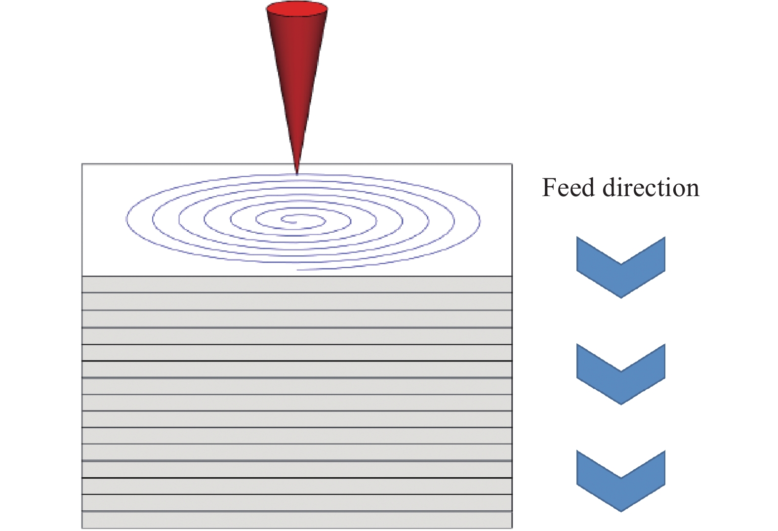
现阶段超短脉冲激光钻孔主要有四种工艺路线,分别为:单脉冲钻孔、多脉冲钻孔、环钻和螺旋钻孔[7-8] ,如图1所示。四种制孔方式所能达到的精度从高到低依次为:螺旋钻孔、环钻、多脉冲钻孔和单脉冲钻孔。然而,钻孔所需时间却往往是相反的。相比于其他钻孔形式,螺旋钻孔由于加工过程中激光光斑沿螺旋轨迹运动,并随着材料的去除焦点不断向下运动,可提高激光能量的利用率,同时也可改善由于激光光斑能量分布不均匀产生的孔形误差[9-10]。
Yuan D Q[11]等人研究了激光功率对孔表面形貌的影响,结果表明:当功率很小时,能量不足以烧蚀材料,随着功率的增加,孔径不断增大,但功率过高时,入口处由于热损伤会产生沉积层。Liu Yongsheng[12]等人研究了单层进给量对制孔的影响,发现随着单层进给量的增加,出口圆度降低,孔径减小而入口基本不变。Zhang Ruoheng[13]等人研究了扫描时间对孔锥度的影响,发现随着扫描时间的增加,孔的锥度到达一定值后保持不变,因此,加工时间存在一个兼顾锥度与效率的最优值。
文中通过数值模拟对影响微孔水流量的各个因素进行分析,并根据模拟结果进行螺旋制孔试验,分析了单脉冲能量、单层扫描时间和单层进给量对孔径的影响规律,最终使孔径偏差控制在±5 μm内,水流量测试合格。
-
试验采用的材料为锻态GH3044镍基合金平板,尺寸为50 mm×10 mm×1.5 mm (长×宽×厚)。激光制孔前用酒精擦拭试板表面,以去除油污等异物。
-
试验中使用五轴飞秒激光制孔加工系统,如图2所示。激光经过λ/4波片变为圆偏振光,旋转光楔模块可以获得设置的旋转半径,之后经过聚焦模块到达工件,在加工过程中聚焦模块及喷嘴可以整体向下进给。文中设备采用脉冲宽度为200 fs的高功率激光器,最大功率可达20 W,最大重复频率600 kHz,激光波长为1030 nm。

图 2 加工系统示意图
Figure 2. Schematic diagram of the machining system
制孔后将试板置于乙醇中使用超声清洗机清洗30 min,采用KEYENCE VHX-1000E正置式超景深光学显微镜对微孔进行观察。采用OLS-3000激光扫描共聚焦显微镜观察微孔内壁的粗糙度,观察前用砂纸将微孔打磨至内壁裸露状态。
试验采用平面螺旋扫描的方式进行制孔,加工过程中,光斑在聚焦水平面内做平面螺旋运动,同时配合向下的进给,从而保证微孔出入口孔径的一致性,如图3所示。
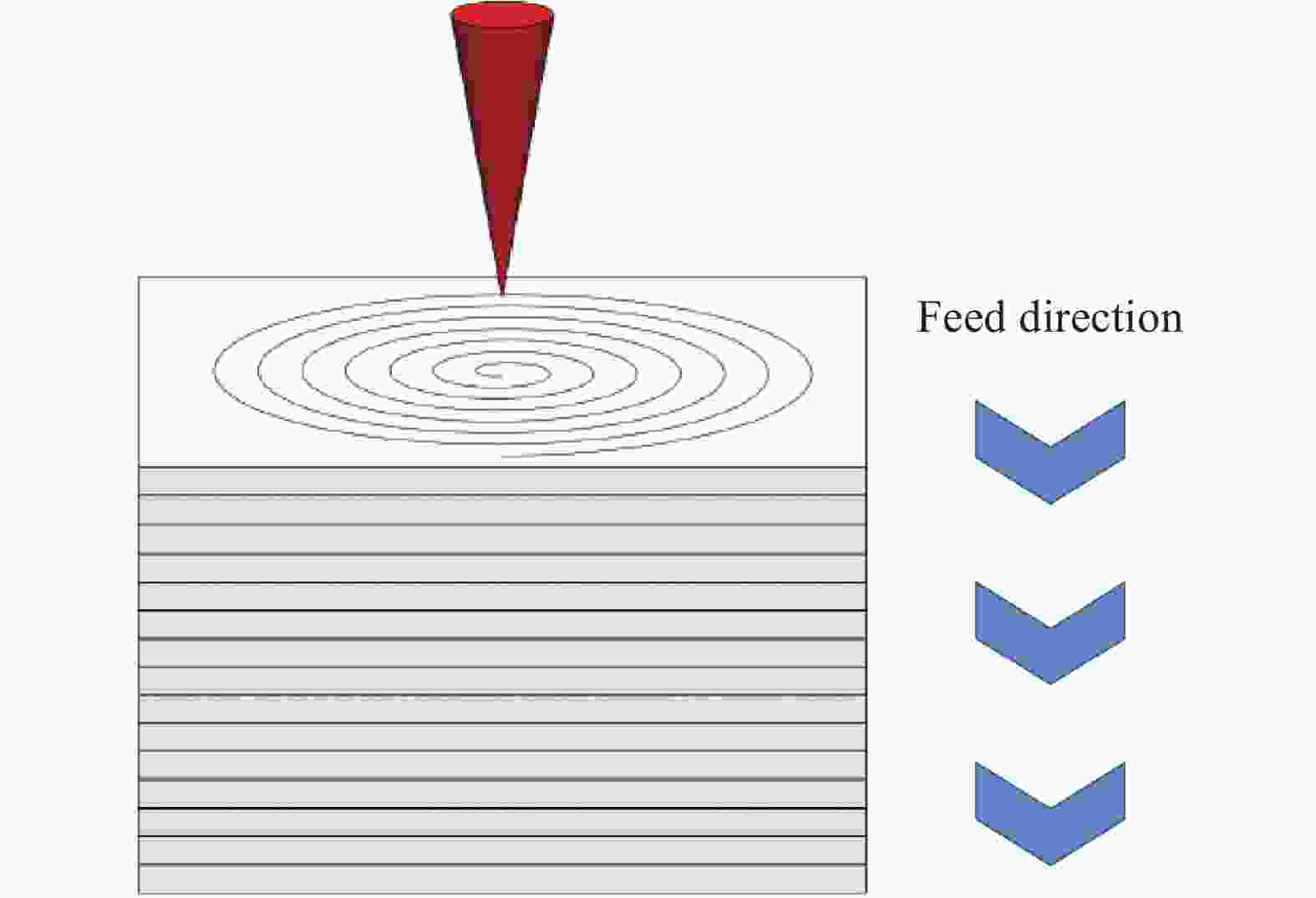
图 3 螺旋扫描路径示意图
Figure 3. Schematic diagram of the spiral scan path
试验所采用的工艺参数如表1所示。使用压缩空气作为保护气体,试验前调整激光焦平面位置与试板上表面重合。
表 1 工艺参数表
Table 1. Process parameters table
Parameters Value Rotation speed/r·min−1 2 400 Laser frequency/kHz 100 Single pulse energy/μJ 20-140 Single layer feed/mm 0.01-0.04 Single layer scanning time/ms 200-1 200 使用北京动力机械研究所专用装置进行流量测试,如图4所示。由于油测试试验经济性较差,在以往研究中,均以水代替油,所有水流量测试指标均由油测试指标换算而来。测试过程如下:将制孔后的试板固定在夹具上,打开水泵,设置恒压1 MPa,水流通过输送管道,流经小孔后射入容器,待10~20 min后水流稳定开始收集,收集时间为1 min。
图 4 流量测试装置示意图
Figure 4. Schematic diagram of the flow test apparatus
-
为了从理论上分析制孔质量对孔流量的影响规律,采用Ansys Fluent软件开展了数值模拟研究。
-
流体在强压力的作用下快速流经输送管道,通过试板上的微孔后喷射到空气中,故模型按照三维流动来进行分析。考虑到输送管道内液体流动情况的复杂性,在数值模拟中作出如下简化和假设:
(1)流动为不可压流,不考虑流动中压力变化对流体密度的影响 ,不考虑高压下流体的可压缩性变化;
(2)不考虑流动中热传导的作用。
计算过程中采用Fluent软件求解质量和动量守恒方程,由于已假定流动为不可压流动,且不考虑热传导的作用,所以不需要求解能量方程。
-
(1)实体模型建立及网格划分
研究对象为微孔水流量,对其建立流道物理模型。模型整体由流体管道、试板、收集容器三部分组成。微孔位于试板中心并与流体管道相连。为了进一步简化模型,提取流体区域作为计算区域,如图5所示。其中管道为半径6 mm、高10 mm的圆柱,孔的尺寸(直径和高度)为可变参数,容器为半径10 mm、高20 mm的圆柱。

图 5 物理模型
Figure 5. Physical mode
计算网格为六面体网格,由于相对于整个计算域,微孔的几何尺寸较小,为了得到比较精确的结果,对网格划分采用疏密结合的方式,对小孔部分的网格进行了细化,整个计算域的网格数约为80万。
(2)边界条件及初始化条件设置
在实际测试中,进口水流为恒定压力1 MPa,考虑到可能会有回流情况产生,故采用压力出口边界条件,设置为一个标准大气压。除此之外,其余面均为Wall。
为了简化模型,初始条件设置为管道内充满水,微孔和容器内均为空气。在入口压力的作用下,水流通过微孔到达容器并从出口射出。
-
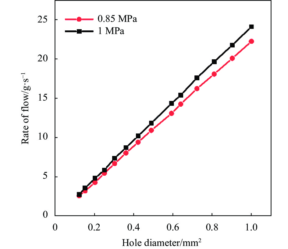
小孔高度设置为1.5 mm,在入口压力分别设置0.85 MPa和1 MPa条件下,分别取不同大小的孔径,模拟测得的结果曲线如图6所示,水流量与孔径的平方近似呈线性关系。

图 6 孔径平方对水流量影响的关系曲线
Figure 6. Curve of square of the hole diameter versus water flow
-
小孔孔高设置为1.5 mm,锥度用孔壁与垂直方向的夹角表示,如图7所示。在保证孔入口或出口直径为1 mm的前提下,选用锥度0~5°上的部分特征点,得到的锥度-流量曲线如图8所示。由曲线可知,小孔的水流量的大小是由出入口孔径共同决定的。小孔的入口、出口孔径越大,水流量越大。

图 7 锥度的表示方法
Figure 7. Representation of taper
图 8 锥度对水流量影响的关系曲线
Figure 8. Curve of taper versus water flow
-
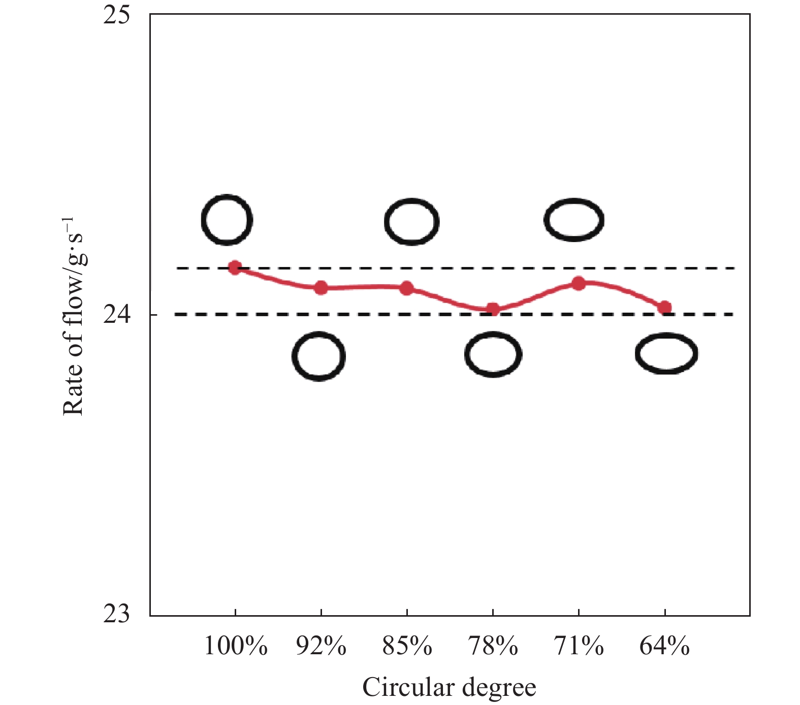
为了探究圆度对流量的影响,在保证出入口面积相等的前提下,分别设置孔截面为圆形和长径短径之比不同的椭圆形,圆度的计算方法为:
$$ \mathrm{圆}\mathrm{度}=\left(1-\frac{a-b}{a}\right)\times 100{\text{%}} $$ 式中:a为椭圆长径;b为椭圆短径。由此得到的圆度-流量曲线如图9所示。由图9可知,圆度对流量大小基本无影响。

图 9 圆度对流量影响的关系曲线
Figure 9. Curve of circular degree versus water flow
-
为了探究内壁粗糙度对小孔流量的影响,采用粗糙度模型加以计算。
-
由于重点研究孔质量对流量的影响,因此仅对小孔内壁设置不同的粗糙度。在Fluent中,整个粗糙区域分为三个区域。粗糙函数∆B的计算源于Nikuradse’s数据基础上的由Cebeci和Bradshaw提出的公式[14-15]:
对于液体动力光滑区域(
$ K_s^ + $ <2.25):$$ \Delta B{\text{ = }}0 $$ (1) 对于过渡区域(2.25<
$ K_s^ + $ <90):$$ \begin{split} \Delta B{\text{ = }}\frac{1}{\kappa }\ln \left[ {\frac{{K_{{s}}^ + - 2.25}}{{87.25}} + {C_{{{{K}}_{{s}}}}}K_{{s}}^ + } \right] \times \\ \sin \left[ {0.425\;8\left( {\ln K_{{s}}^ + } - 0.811\right)} \right] \\ \end{split} $$ (2) 在完全粗糙区域(
$ K_s^ + $ >90):$$ \Delta B{\text{ = }}\frac{1}{\kappa }\ln \left( {1 + {C_{{{{K}}_{{s}}}}}K_{{s}}^ + } \right) $$ (3) 式中:Ks+为无量纲高度,是由粗糙高度Ks计算得来的;
${C_{{{{K}}_{{s}}}}}$ 为粗糙常数,依赖于粗糙的类型。文中试验设计的粗糙高度分别为10、30、50 μm,粗糙常数设置为0.8。 -
不同孔径下粗糙度对流量的影响如表2所示。结果表明:随着粗糙度的增加,流量减少,且孔径越小,流量降低得越明显。
表 2 内壁粗糙度对流量的影响
Table 2. Effect of internal wall roughness on flow rate
Roughness height/mm Hole diameter/mm Flow deviation 0 0.39 - 1 - 0.01 0.39 −3.30% 1 −0.32% 0.03 0.39 −4.85% 1 −1.21% 0.05 0.39 −5.96% 1 −1.54% -
为了探究孔深对流量的影响,在保证其他因素一致的前提下,得到的孔深-流量关系曲线如图10所示。由图10可知,孔深对流量大小基本无影响。
图 10 深度对流量影响的关系曲线
Figure 10. Curve of hole depth versus water flow
-
钻孔过程中激光光斑在焦平面内沿着螺旋轨迹运动,两个脉冲之间的距离主要是由激光脉冲频率和旋转速度决定的。如果旋转速度过大或者脉冲频率太低,则会导致相邻两个光斑的重叠部分面积较小,从而导致未去除区域面积增大。前期试验的结果表明:旋转速度2400 r/min、激光频率100 kHz的情况下,竖向条纹较少甚至消失,如图11所示。因此文中试验均是在以上工艺参数的基础下进行的。

图 11 孔壁二维形貌对比。(a)有竖向条纹;(b)无竖向条纹
Figure 11. Comparison of two-dimensional morphology of hole walls.(a) With vertical stripes; (b) Without vertical stripes
此外,在试验过程中发现,通过飞秒激光螺旋制孔方式,工艺参数对内壁粗糙度影响较小,所得微孔内壁粗糙度均在Ra0.4~Ra0.5 μm范围内波动,如图12所示。因此,相对于孔径波动对流量的影响,粗糙度对流量的影响可忽略不计。因此,后续工作仅研究不同工艺参数对孔径的影响规律。
图 12 微孔内壁三维形貌及粗糙度曲线
Figure 12. Three-dimensional morphology and roughness curve of the internal wall of the microhole
-
单脉冲能量是靠改变激光功率实现的,采用单脉冲能量分别为20~140 μJ、单层扫描时间1000 ms、单层进给量0.01 mm、预设孔径380 μm进行试验,可以看出,随着单脉冲能量的增加,出入口孔径均增大,且出口增大的趋势更明显,如图13所示。原因在于:由于激光光斑能量呈高斯分布,导致不同单脉冲能量下达到材料去除能量阈值的光斑面积不同,单脉冲能量越大,达到烧蚀阈值能量的光斑面积越大,孔径因此增大。此外,即使在钻孔过程中焦点向下进给,但入口侧始终受到离焦状态下激光能量的辐照,在热量积累的作用下表现为始终大于出口孔径。且由于加工过程中孔内产生的等离子体会吸收部分激光能量,与加工入口侧时相比,加工出口侧时到达出口侧的能量相对较低,导致出口侧孔径的减小。

图 13 单脉冲能量对出入口直径及锥度的影响
Figure 13. Effect of single pulse energy on entrance and exit diameter and taper
-
在文中试验中,为了保证层与层之间加工的均匀性,必须保证单层扫描时间内,激光刚好沿着设定的螺旋轨迹运动结束,再进行下一层的扫描。因此,必须满足单层扫描时间=加工次数/旋转速度。加工次数表示螺旋轨迹从起始圆到结束圆经过了多少圈数。对应地,当单层扫描时间设置为200~1200 ms时加工次数为8~48。
设置单脉冲能量140 μJ、单层进给量0.01 mm、预设孔径350 μm进行试验。由图14可知,随着单层扫描时间的增加,出入口孔径均有不同程度的增大。与单脉冲能量的影响相似,出口直径随扫描时间的增大变化更明显。原因在于:当单层扫描时间较大时,入口孔径首先达到饱和,在后续的钻孔过程中,单层热输入增大,可以去除更多的材料,且热输入的增大可以部分抵消等离子体对激光能量的消极影响,从而适当增加出口孔径,微孔锥度略微降低。

图 14 单层扫描时间对出入口直径及锥度的影响
Figure 14. Effect of single layer scanning time on entrance and exit diameter and taper
-
固定单脉冲能量140 μJ、单层扫描时间800 ms、预设孔径350 μm进行试验。由图15可知,随着单层进给量的增加,出入口孔径均有不同程度的降低,且出口孔径降低程度更明显,原因在于:当焦点下降速度较大时,激光焦点位于待加工层的下方,即形成负离焦,作用于代加工材料的激光能量密度降低,导致局部材料未得到有效去除,整体孔径均减小。且由于整个加工过程中,入口侧始终受到离焦状态下激光的辐照,所以入口侧孔径降低的不明显。因此,实际加工过程中建议单层进给量控制在0.01~0.02 mm。

图 15 单层进给量对出入口直径及锥度的影响
Figure 15. Effect of single layer feed on entrance and exit diameter and taper
-
根据不同工艺参数对孔径的影响规律,选用单脉冲能量140 μJ、单层扫描时间1200 ms、单层进给量0.02 mm、预设孔径390 μm,测得入口孔径394.8 μm,出口孔径394.2 μm,锥度为0.01°,如图16所示。在此工艺下,钻10个孔进行水流量测试,最大流量为3.28 g/s,平均流量为3.23 g/s,最小流量为3.17 g/s,最大偏差1.8%,满足使用要求。由于流量测试试验采用水来代替油,两者密度、粘性等有较大差异,因此无法保证喷孔的雾化性能,所以在水测试试验中对雾化性能不做具体要求。

图 16 微孔表面二维形貌。(a)入口;(b)出口
Figure 16. Two-dimensional morphology of microporous surface. (a) En-trance; (b) Exit
-
文中开展了孔质量对液体流动特性影响的数值模拟研究,并采用激光旋转制孔的方法对上述模拟结果进行验证,并分析了单脉冲能量、单层扫描时间和单层进给量对孔质量的影响。得出的主要结论如下:
(1)小孔流量主要由出入口孔径大小决定,在该孔径相同的前提下,孔深度及圆度对孔流量基本无影响。
(2)孔壁粗糙度越大,流量越小,且对小孔径影响更显著。当粗糙高度为0.01 mm、粗糙系数为0.8时,0.39 mm孔径流量降低3.30%,1 mm孔径流量仅降低0.32%。
(3)单脉冲能量对孔径及锥度的影响最显著,单脉冲能量越大,出入口孔径增加,锥度降低。
(4)单层扫描时间和单层进给量对孔径和锥度的影响不明显。单层扫描时间的延长和单层进给量的减小均会使锥度略微降低,甚至在0.01 mm的单层进给量下得到了0°,推荐加工过程中的单层进给量控制在0.01~0.02 mm。
(5)通过优化工艺,使孔径偏差控制在±5 μm内,锥度为0.01°,水流量最大偏差1.8%,满足使用要求。
Numerical simulation of oil supply holes flow and optimization of its femtosecond laser processing technology
-
摘要: 航天发动机供油装置的喷油流量均匀性是决定其性能质量的关键技术指标,其中供油孔的形状尺寸、内表面状态是喷油流量的重要影响因素。传统的供油孔加工方法以电火花加工为主,存在较厚的重铸层,且加工效率低。而激光制孔为典型的非接触式制孔方法,具有加工效率高、质量好,重铸层少的显著优势。为满足某型号航天发动机供油装置的高效高质量制造要求,采用脉宽为200 fs的超短脉冲飞秒激光螺旋制孔工艺,针对1.5 mm厚的GH3044镍基合金材料开展了以0.39 mm孔径为加工基准的流量数值模拟及工艺试验研究。首先通过数值模拟手段,研究了孔径、圆度、锥度以及内壁粗糙度对供油孔流量的影响规律和控制手段,之后根据模拟所获得的理论结果,通过飞秒激光制孔试验对制孔工艺进行了优化。研究发现,出入口孔径是决定流量大小最重要的因素,在单脉冲能量140 μJ,单层扫描时间1200 ms,单层进给量0.02 mm,重复频率100 kHz,旋转速度2400 r/min的工艺下,将孔径偏差控制在±5 μm以内,最终成功实现了供油孔流量偏差1.8%的制孔效果。Abstract:
Objective The uniformity of oil injection flow of the aerospace engine oil supply device is a key technical index to determine its performance quality, in which the shape and size of the injection hole and the state of the internal surface are important influencing factors of the oil injection flow. The traditional oil injection hole processing method is based on EDM, there is a thick recast layer, and the processing efficiency is low. The laser hole is made with a typical non-contact hole making method, which has significant advantages of high processing efficiency, good quality and less recast layer. In order to meet the high-efficiency and high-quality manufacturing requirements of a certain type of aerospace engine fuel supply device, the ultra-short pulse femtosecond laser screw hole making process with a pulse width of 200 fs was adopted, and the flow numerical simulation and process test study with 0.39 mm hole diameter as the processing benchmark were carried out for the 1.5 mm thick GH3044 nickel-based alloy material. Methods By means of numerical simulation, the effect of hole diameter (Fig.6), taper (Fig.8), roundness (Fig.9), internal wall roughness (Tab.2) and hole depth (Fig.10) on the flow rate of oil supply hole is studied. The effect of single pulse energy (Fig.13), single layer scan time (Fig.14) and single layer feed (Fig.15) on the hole diameter is analyzed, and the hole diameter deviation is controlled by process optimization to ensure the flow stability. Results and Discussions Numerical simulations were used to investigate the factors influencing the hole flow rate. The results show that the hole diameter is the main factor affecting the hole flow rate, and the flow rate is linearly related to the square of the hole diameter (Fig.6). The internal wall roughness has an inhibitory effect on the flow rate of holes. For a 0.39 mm diameter micro-hole, the flow rate is reduced by 3.3% when the roughness is 0.01 mm and by 5.96% when the roughness is 0.05 mm (Tab.2). The roundness (Fig.9) and height (Fig.10) of the micro-hole had no significant effect on the flow rate. Since the hole internal wall roughness of the femtosecond laser hole making was low and did not change significantly for different process parameters, only the effects of single pulse energy, single layer scan time and single layer feed on the micro-hole diameter were investigated. The process optimization was carried out according to the effect law of different process parameters on the micro-hole diameter. Using the optimized process for drilling, the maximum deviation of micro-hole water flow rate is finally less than 1.8% to meet the usage requirements. Conclusions In this paper, the influence law of micro-hole quality on water flow is studied by numerical simulation. The micro-hole flow rate is mainly determined by the diameter of the hole entrance and exit. Under the premise of the same entrance and exit hole diameter, the depth and roundness of the hole have basically no effect on the hole flow rate. The larger the roughness of the internal wall of the micro-hole is, the smaller the flow rate is. The smaller the hole diameter is, the more significant the effect of roughness is. When the roughness height is 0.01 mm, the flow rate of 1 mm diameter is reduced by 0.32%, and the flow rate of 0.39 mm diameter is reduced by 3.30%. The effect of process parameters on the micro-hole diameter was analyzed. With the increase of single pulse energy, the entrance and exit hole diameter increased simultaneously and the taper decreased. The effects of single layer scan time and single layer feed on hole diameter were not significant. Finally, the deviation of the hole diameter was controlled within ±5 μm and the taper was 0.01° by process optimization. The water flow rate test was conducted, and the maximum flow rate was 3.28 g/s, the minimum flow rate was 3.17 g/s, and the average flow rate was 3.23 g/s with a maximum deviation of 1.8%, which satisfied the usage requirements. -
Key words:
- femtosecond laser /
- oil injection hole /
- numerical simulation /
- helical drilling
-
图 11 孔壁二维形貌对比。(a)有竖向条纹;(b)无竖向条纹
Figure 11. Comparison of two-dimensional morphology of hole walls.(a) With vertical stripes; (b) Without vertical stripes
图 12 微孔内壁三维形貌及粗糙度曲线
Figure 12. Three-dimensional morphology and roughness curve of the internal wall of the microhole
图 13 单脉冲能量对出入口直径及锥度的影响
Figure 13. Effect of single pulse energy on entrance and exit diameter and taper
图 14 单层扫描时间对出入口直径及锥度的影响
Figure 14. Effect of single layer scanning time on entrance and exit diameter and taper
图 15 单层进给量对出入口直径及锥度的影响
Figure 15. Effect of single layer feed on entrance and exit diameter and taper
图 16 微孔表面二维形貌。(a)入口;(b)出口
Figure 16. Two-dimensional morphology of microporous surface. (a) En-trance; (b) Exit
表 1 工艺参数表
Table 1. Process parameters table
Parameters Value Rotation speed/r·min−1 2 400 Laser frequency/kHz 100 Single pulse energy/μJ 20-140 Single layer feed/mm 0.01-0.04 Single layer scanning time/ms 200-1 200  下载: 导出CSV
表 2 内壁粗糙度对流量的影响
Table 2. Effect of internal wall roughness on flow rate
Roughness height/mm Hole diameter/mm Flow deviation 0 0.39 - 1 - 0.01 0.39 −3.30% 1 −0.32% 0.03 0.39 −4.85% 1 −1.21% 0.05 0.39 −5.96% 1 −1.54%
下载: 导出CSV
-
[1] Marimuthu S, Elkington H, Smith B. Millisecond fibre laser drilling of thick-section aerospace alloy [J]. The International Journal of Advanced Manufacturing Technology, 2022, 119(5): 3437-3447. doi: 10.1007/s00170-021-08435-y [2] Ohnabe H, Masaki S, Onozuka M, et al. Potential application of ceramic matrix composites to aero-engine components [J]. Composites Part A: Applied Science and Manufacturing, 1999, 30(4): 489-496. doi: 10.1016/S1359-835X(98)00139-0 [3] Sezer H K, Li L, Schmidt M, et al. Effect of beam angle on HAZ, recast and oxide layer characteristics in laser drilling of TBC nickel superalloys [J]. International Journal of Machine Tools & Manufacture: Design, Research and Application, 2006, 46(15): 1972-1982. doi: 10.1016/j.ijmachtools.2006.01.010 [4] Wang Chunhui, Zhang Litong, Liu Yongsheng, et al. Ultra-short pulse laser deep drilling of C/SiC composites in air [J]. Applied Physics A Materials Science& Processing, 2013, A111(4): 1213-1219. doi: 10.1007/s00339-012-7377-5 [5] Holder D, Weber R, Graf T, et al. Analytical model for the depth progress of percussion drilling with ultrashort laser pulses [J]. Applied Physics A Materials Science & Processing, 2021, 127(5). doi: 10.1007/s00339-021-04455-3 [6] Franco A, Rashed C A A, Romoli L. Analysis of energy consumption in micro-drilling processes [J]. Journal of Cleaner Production, 2016, 137: 1260-1269. doi: 10.1016/j.jclepro.2016.07.188 [7] Zibner F, Fornaroli C, Holtkamp J, et al. 1 μm adjustment-tolerance for high-precision helical laser drilling[C]//Proc SPIE, Optical System Alignment, Tolerancing, and Verification IX, 2015, 9582: 95820C. [8] Lee H M, Choi J H, Moon S J. Determining the machining parameters for femtosecond laser helical drilling of aluminosilicate glass substrate [J]. International Journal of Precision Engineering and Manufacturing, 2017, 18(7): 923-930. doi: 10.1007/s12541-017-0109-1 [9] Lendner F. Smart ultra short pulse laser processing with rotating beam: laser micro drilling, cutting and turning[C]//Proc SPIE, Laser-based Micro- and Nanoprocessing XIV, 2020, 11268: 112681Z. [10] Fornaroli C, Holtkamp J, Gillner A. Laser-beam helical drilling of high quality micro holes [J]. Physics Procedia, 2013, 41: 661-669. doi: 10.1016/j.phpro.2013.03.130 [11] Yuan D Q, Di J K, Zhou M, et al. Formation and characteristics of through holes with picosecond-laser helical drilling on alloy material [J]. Journal of Russian Laser Research, 2017, 38(2): 191-198. doi: 10.1007/s10946-017-9633-9 [12] Liu Yongsheng, Wang Chunhui, Li weinan, et al. Effect of energy density and feeding speed on micro-hole drilling in C/SiC composites by picosecond laser [J]. Journal of Materials Processing Technology, 2014, 214(12): 3131-3140. doi: 10.1016/j.jmatprotec.2014.07.016 [13] Zhang Ruoheng, Li Weinan, Liu Yongsheng, et al. Machining parameter optimization of C/SiC composites using high power picosecond laser [J]. Applied Surface Science, 2015, 330: 321-331. doi: 10.1016/j.apsusc.2015.01.010 [14] Katopodes N D. Free-Surface Flow: Environmental Fluid Mechanics, Chapter 8-Turbulent Flow[M]. Oxford, United Kingdom: Butterworth-Heinemann, 2019: 566-650. [15] Nakayama Y. Introduction to Fluid Mechanics[M]. Oxford, United Kingdom: Butterworth-Heinemann, 2018. -

 点击查看大图

计量
- 文章访问数: 160
- HTML全文浏览量: 30
- PDF下载量: 21
- 被引次数: 0


