


-
光波在大气中传播时,由于折射率分布随空间位置发生改变,其波面会产生一定程度的畸变。因此,量化和观测由折射率变化导致的波前畸变与引起这种畸变的位相介质具有非常重要的意义[1]。
视宁度是评价观测目标受到湍流影响的物理量,表现为对于波前畸变的影响程度。视宁度分为三种:大气视宁度、圆顶视宁度、镜面视宁度。在大气的边界层和顶层之中,是湍流剧烈活动的区域,而两种介质交接处的剧烈湍流活动是导致成像闪烁和模糊的重要原因,视宁度为目标受到湍流影响而发生模糊与闪烁的物理量。经历了几十年的发展,带有自适应光学的仪器基本上能够克服大气湍流的影响,达到衍射极限,从而实现较好的大气视宁度。而圆顶视宁度是指由于圆顶和周围环境分离导致的成像质量变差。早期,科学界广泛认为把圆顶设计成半圆形上开一个狭缝能够减小圆顶对于视宁度的影响,但后来多重镜面望远镜(Multiple Mirror Telescope, MMT)的带有锋利边缘的矩状圆顶推翻了这一设计。到现在可以通过合理的设计圆顶结构和一些热控设备、环境控制设备来减小圆顶视宁度,提高观测质量。以美国牵头的30 m望远镜(Thirty Meter Telescope, TMT)、巨型麦哲伦望远镜(Giant Magellan Telescope, GMT)和欧洲极大天文望远镜(European Extremely Large Telescope, E-ELT)是目前世界上正在开展的3个30 m级别的巨型望远镜。这些口径不断增大的望远镜逐渐凸显出了镜面视宁度研究的重要性。
镜面视宁度在成像系统中是指镜面湍流所导致的成像质量变差,而在镜面的加工检测之中则主要是指对于干涉仪等检测方法波前畸变的影响。望远镜等系统处于工作状态时,由于其携带设备可能会对观测的热环境产生影响,所以评价系统应用的集成对于望远镜等光学系统来说具有重要意义。而镜面视宁度的检测正是对于这种集成应用检测评价的重要方法。由于系统热环境的改变,必然会使镜面视宁度发生变化,因此对于不同状态下的系统集成结果可以使用镜面视宁度来进行评定。
镜面视宁度可以使用结构函数、半高全宽(Full Width at Half Maxima, FWHM)与标准化点源敏感性(normalized Point Source Sensitivity, nPSS)等来评价。结构函数是Kolmolgorov引入来描述气象参数随机变化过程的,包括温度结构函数和折射率结构函数等,早期常用折射率结构函数来描述视宁度,其值越小就代表着两点间的折射率差异就越小,相应的视宁度就越小,对于成像或者加工就越有利。但是折射率结构函数本身会随高度变化,很难定性的描述视宁度。所以在面形加工等一些需要精确知道视宁度影响的场景中是不适用结构函数的。半高全宽相对于结构函数来说,是能够定量描述视宁度的,其值越小就代表着能量的集中程度越高。但是这种方法存在一个问题——只能评价镜面或者是系统中央区域,这对于系统集成检测来说是很难进行全面的定量评价的。nPSS是TMT团队提出的一种新型评价方式,由于其具有合成性这一优势,能够全面评价各方面对于视宁度的影响,所以这种方法更适用于存在多方面因素影响视宁度的情况。
指标均方根RMS在加工检测中得到广泛的应用,但是这种指标较适用于低频面形的检测应用之中。由于大气湍流是一种频率范围分布较为广泛的误差,所以由大气湍流导致的波前误差与镜面加工时的波前误差的统计误差特性是不一样的。因此,相对于RMS来说,nPSS在评价镜面视宁度是更加具有优势的,能够在全频域中进行更加精确的评价。而半高全宽FWHM与结构函数是天文学与自适应光学中对于大气湍流的一种评价,是较长路径的一个积分平均的结果。镜面视宁度是由于镜面有限距离处的镜面湍流所影响的,只受镜面小环境的影响,不受望远镜站址等影响。所以,相对于一些面形检测上的评价指标与其他领域对于湍流影响的评价指标来说,nPSS能够全面地对镜面视宁度进行评价,在镜面视宁度的检测之中往往使用nPSS进行一个较为准确的评价。在nPSS提出之后,这些可能可以应用到镜面视宁度检测上的一些方法,最后在进行评价时,如果想要一个更为精确的表达,也会最终落实到nPSS上。
文中主要从一维检测方法到三维检测方法阐述能够应用于镜面视宁度检测上的不同方法。一维方法是一种线检测方法,只能对有限区域的平均镜面视宁度进行测量,主要阐述了自准直仪的方法,该方法利用自准直仪发出的经过被测区域后反射回来的光与发射光之间偏差来测量经过区域内的平均视宁度,因为测量区域的限制,只能够做到有限区域内的测量。二维方法从面检测方法出发,将光线经过被检区域对于波前的影响投影到同一平面上,主要阐述了曲率/斜率方法、全息波前传感与剪切干涉的方法,曲率/斜率方法通过得到经过被测区域内波前的形状来反演出整个镜面的视宁度分布。全息波前传感利用带有不同模式像差的波前经过偏置板后会在像面特定位置处出现亮度不同的亮斑,通过解算亮斑强度与模式强度之间的关系来得到经过被测区域后的波前各模式系数,以此来得到镜面视宁度。剪切干涉仪原理与传统干涉仪原理类似,通过测量实际波前与理想波前的干涉条纹来得到被测区域对于入射波前的影响。三维方法为体检测方法,能够得到被测区域每个剖面对于镜面视宁度的贡献,主要是从全息粒子测速这个方向来阐述其在镜面视宁度上的应用。通过记录参考光与湍流处粒子的散射光干涉图样,衍射重现其分布,并引入时差进行粒子测速。温度场的方法利用镜面与环境之间的温度差来解算出半高全宽,进而来评价镜面视宁度。
-
传统望远镜因为口径小,受到湍流的影响较小,所以在面形加工与安装检测中并不会考虑到镜面视宁度的影响。随着对望远镜口径要求的逐渐加大,镜面视宁度检测这个问题也就变得越来越重要了。早期,视宁度的检测是通过共用望远镜光路来实现的。如美国国家光学天文台(National Optical Astronomy Observatory, NOAO)利用位于焦点的干涉仪以及日本斯巴鲁望远镜(Subaru Telescope, SUBARU)利用主光学系统观测的间隔来进行视宁度测量,斯巴鲁望远镜视宁度分布情况如图1所示,用FWHM表示大致在0.7″左右。凯克望远镜II型(KECK II)望远镜坐落于美国夏威夷莫纳克亚天文台,是一个10 m级别的望远镜,该望远镜携带闪烁计数器,通过测量接收光电子幅值差异来确定镜面视宁度[2],并给出了主镜段上的大气倾斜功率谱,得到镜面附近的视宁度大致在0.3″左右。这些镜面视宁度的测量装置装配在望远镜上后就很难再进行更改,需要为每台望远镜单独定制设备,这对于工程应用来说是非常不利的,会增加望远镜的成本,于是镜面视宁度的检测装置便朝着简便化和普遍化不断发展。
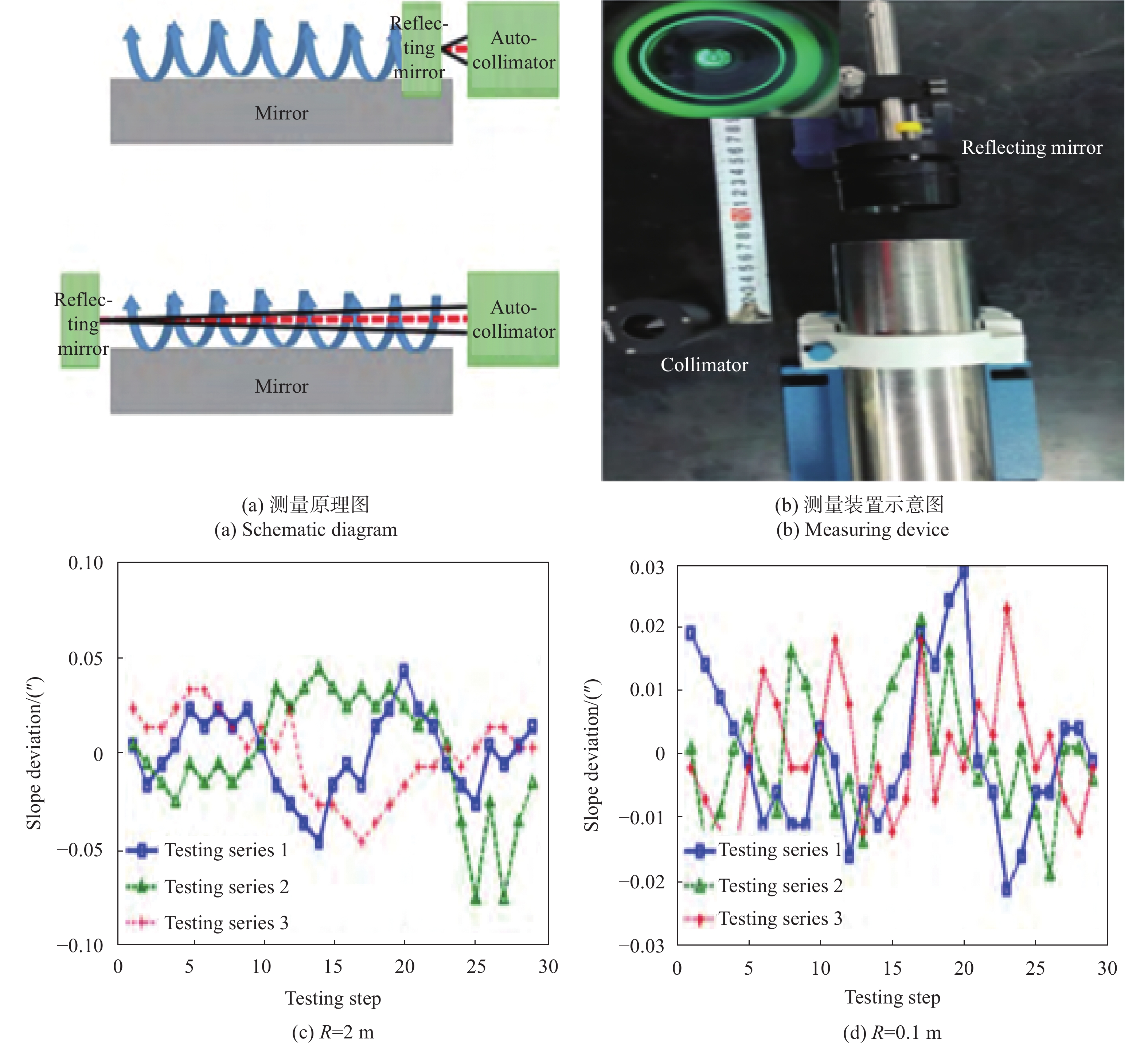
利用电子自准直仪来进行镜面视宁度测量是一种更具优势的测量方法。1989年,Malley提出了一种基于电子自准直仪的镜面视宁度简便测量装置。电子自准直仪发出的光通过镜面表面湍流区域,被平面镜反射之后重新由自准直仪接收,通过湍流的流向与发射光和接收光之间的角度偏差反演出光束通过部分的镜面视宁度。增加电子自准直仪的数量可以加大视宁度测量的区域。这种视宁度测量装置能够对光通过的一定体积进行视宁度的测量,使用上相对简便,只需要一台电子自准直仪与反射镜就能够测量镜面视宁度。但是这种测量装置存在一个主要的缺陷——测量区域有限。单次测量只能够得到其口径区域内的平均视宁度,即使使用多台电子自准直仪也仍要考虑到采样频率和拼接的问题,难以在变化快速的镜面湍流中得到大范围的镜面视宁度分布。杨飞[4]等通过电子自准直仪实现了镜面视宁度的检测,利用三台自准直仪与六自由度平台使测量精度提升到了0.01″,在仿真中计算了两个方向的斜率功率谱与原始波前功率谱,得到了两个方向的nPSS为0.999,其原理与测量结果如图2所示。
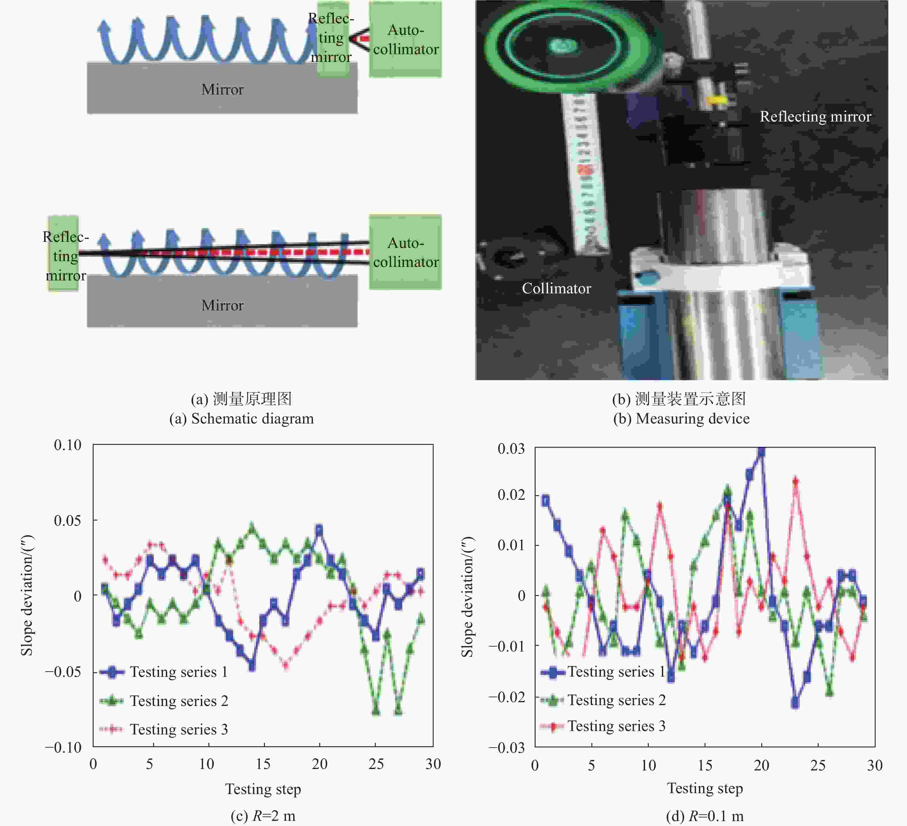
自准直仪发出的准直激光束在通过湍流区域后被镜面反射,重新被自准直仪所捕获,并形成一个亮斑。因为湍流等其他外界因素的作用,导致重新接收的亮斑会在位置上产生一定的偏移,同时亮斑本身会在一定程度上产生弥散。事实上,弥散是不被允许的,可以通过图像处理的办法来找到亮斑的质心。发射光斑与接收光斑的位置差异就代表着光束经过区域内的镜面视宁度。可以由不同测量距离的斜率结果看到,使用这种自准直仪方法能够测量实验环境下湍流的变化导致镜面视宁度的变化。这种自准直仪测量镜面视宁度的方法经过几十年的发展,已变得非常成熟了。使用nPSS来评价镜面视宁度时,当自准直仪的分辨率为0.005″时,镜面视宁度的分辨率可以达到0.000 3;当自准直仪的重复性为0.03″时,镜面视宁度的表征nPSS重复性可达0.003。镜面视宁度的精度直接与自准直仪的精度相联系,所以提高这种测量方法的测量精度的一个方向就是使用高精度的自准直仪。值得注意的是,如果是在不需要得到整个镜面视宁度的情况下,即只需要得到局部小区域的镜面视宁度,使用自准直仪这种方法是一个较好的选择。在面形加工检测这种应用上,使用自准直仪来进行测量,技术上是完全成熟的。而且,这种方法在水平方向上进行镜面视宁度的检测,当被检镜面尺寸不断增大时,其检测精度是不会受到影响的,但是想要得到整个镜面视宁度的分布还是存在困难的。对与拼接镜面来说,其包络并不会影响这种测量方法的精度。
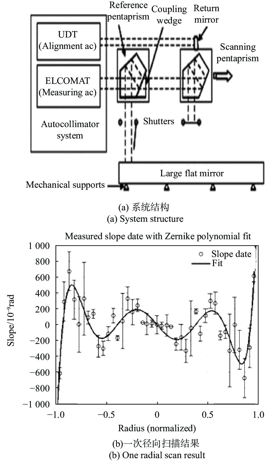
随着镜面视宁度在望远镜口径逐渐加大的推动下而变得越来越重要,科学家对镜面视宁度的研究也在不断深入。J H Burge[5]等研究了使用摆动平面镜与五棱镜扫描装置来检测大型反射镜,其装置如图3所示。测量了1.6 m平面镜,得到其面形均方根值为12 nm,不确定度达到了9 nm rms,利用两个五棱镜构成扫描装置与其对于入射光角度误差不敏感的特性对被检平面镜进行扫描测量给镜面视宁度的检测提供了思路。国内的安其昌[6]等将曲率/斜率混合传感应用到镜面视宁度的检测之中,提高了镜面视宁度检测的精度,实现了镜面视宁度大动态范围的测量,并用实验证明了在热扰动流场较为均匀时,由于湍流不稳定引入的nPSS为0.9718。
-
利用电子自准直仪来测量镜面视宁度的方法本质上还是属于一种斜率的波前探测方法,但这种斜率的探测方法会受到电子自准直仪口径的影响,不能够进行大范围的视宁度检测,将Hartmann-Shack波前探测器应用到镜面视宁度的检测中无疑是对传统一维检测方法的提升。20世纪80年代,亚利桑那州立大学的Roland Shack改进了哈特曼屏技术,用微阵列透镜取代圆盘上的小孔洞,形成了Hartmann-Shack波前探测器,该探测器的提出原本是为了应用在美国军方装备上,后来在自适应光学中得到了更为广泛的发展。基于这种波前斜率的探测,衍生出金字塔波前传感器。相对于Hartmann-Shack波前传感器,金字塔波前传感器具有更大的动态范围,更高的灵敏度,并首次在伽利略意大利国家望远镜的自适应光学系统TNG中得到了应用,欧洲南方天文台的VLT和美国大型双筒望远镜也把这种传感器列入了研究范围。
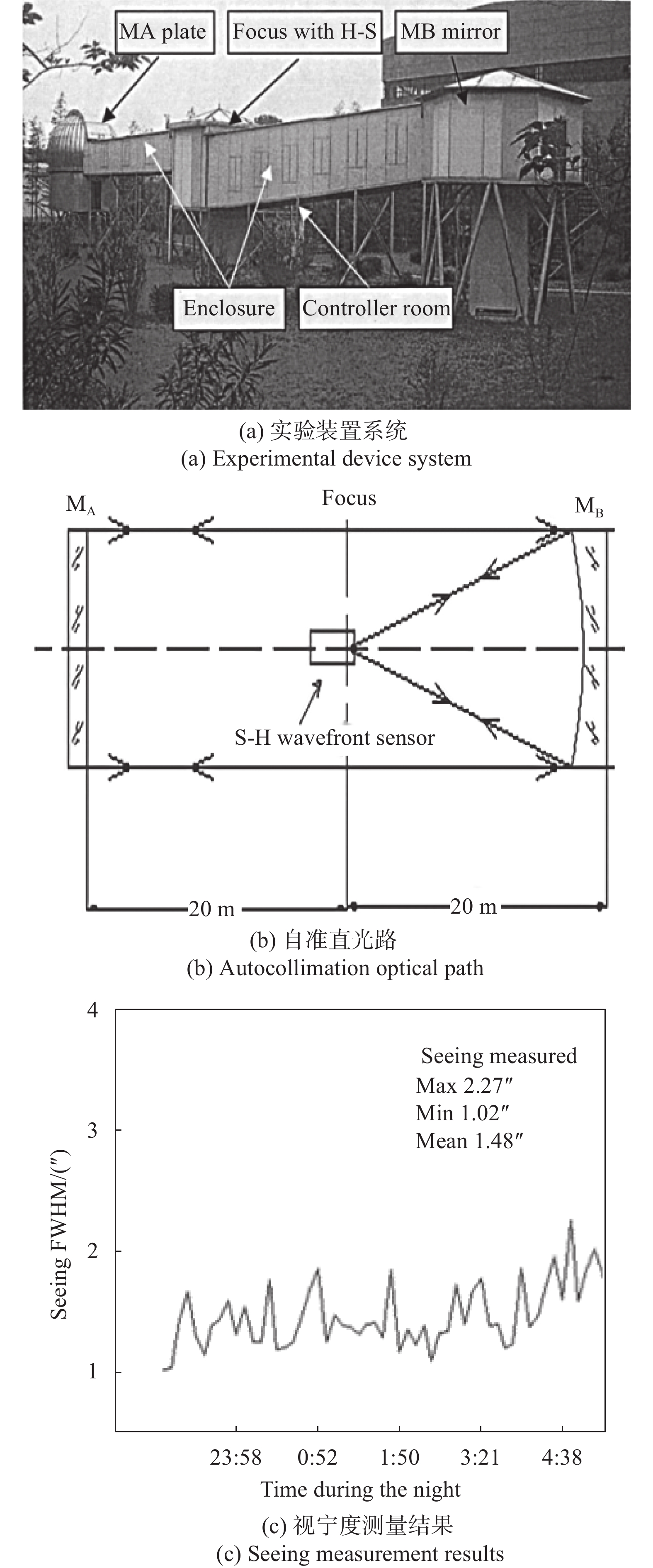
如图4(b)所示,微透镜阵列将入射波前划分成了数个子波前,每个子波前都会在CCD上形成一个像。理想情况下,CCD上的点源像分布应该是规则分布,当入射波前受到湍流等其他的影响而导致波前发生畸变时,其在CCD上的像分布就会发生改变,通过测量相对的改变量,得到重构矩阵,进而反演出入射波前的几何形状。与自准直仪相比,Hartmann-Shack波前传感器能够反演出整个入瞳面上的波前,能够对更大区域处的镜面视宁度进行检测。所以,利用Hartmann-Shack波前传感器来进行镜面视宁度的检测理论上是要比自准直仪法具有更大优势的。30 mm口径,1500个微透镜的波前传感器的测量精度能达到λ/100,重复性精度为0.4 nm。传统的Hartmann-Shack波前传感器带宽在10 kHz的量级。在镜面视宁度的检测之中,虽然镜面湍流对于波前畸变幅值改变小,但是改变速度却很快,这就要求镜面视宁度的测量必须要有一定大小的带宽。如何增大其动态范围一直是科学工作者的研究重点,许多改进的结构与算法都能够提高系统的动态范围,因而将其应用于镜面视宁度的检测之中可行的。被检镜尺寸的增加会导致检测光路的不断加长,而光路的加长会导致检测精度容易受到其他因素的影响。早在21世纪初,国内的张勇[9]等就将Hartmann-Shack波前传感器应用到了视宁度的检测之中,原理结构如图5所示。

在大天区面积多光纤光谱望远镜LAMOST中由于光路过长与接近地面导致在光路周围的围挡会对视宁度产生重要的影响,故在焦面处放置一个Hartmann-Shack波前传感器来测量围挡对于视宁度的影响。放置在B镜焦面处的Hartmann-Shack波前传感器上的点光源发出的光经过B镜反射后变成平行光,经过围挡区域后被A镜返回,并重新汇聚在Hartmann-Shack波前传感器的焦点上。通过对接收波前的重构分析其成成像后的半高全宽,得到了图5 (c)所示的视宁度测量结果。围挡视宁度的测量给镜面视宁度的测量提供了一个非常好的思路,且这种视宁度的测量装置理论上是能够直接应用到镜面视宁度的检测之中的。但是,在面形加工检测之中,应当注意到加工或者被检面本身存在的一个面形误差。
国内外针对这种基于斜率测量的波前传感器的研究是非常充分的。国外的Iuliia Shatokhina[7]等总结了金字塔型波前传感器的各种波前重建算法,并从底层原理和重建精度等方面作出了详细的对比,为接下来镜面视宁度装置研究提供了方向;Ilya Galaktionov[10]等研究了在Hartmann-Shack波前传感器中使用β样条曲面拟合的办法来重构波前,并对一些低阶像差波前进行了实验验证,得到了较好的结果;Noam Sapiens[11]研究了反向Hartmann-Shack波前传感器在眼睛屈光度上的检测,提出了一种二维图形对齐方案,实现了两次测量就能够得到眼睛屈光度的准确值;Rukosuev A. L[12]等在实验室条件下利用Hartmann-Shack波前传感器研究了激光通过大气湍流后的波前畸变,并与实际情况相比,得到了较为相似的结果。国内张昊[8]等基于传统的Hartmann-Shack波前传感器进行改进,利用扫描的方法实现大口径的镜面检测,极大地降低了大口径镜面的检测成本,规避了运输过程产生的风险。吴伟[13]等将Hartmann-Shack波前传感器与计算机技术结合,推导出装调误差与子孔径斜率之间的关系,提出了一种基于光学系统失调前后点阵光斑质心偏差信息的计算机辅助装调方法,并在实验中验证了使用该方法最终能够实现微米级别的装调。韩妍娜[14]等基于迭代外推法给出了一种提高Hartmann-Shack波前传感器动态范围的方案,使每个微透镜的光斑在超出其口径范围内仍然能够正常工作。钱思羽[15]等深入研究了Hartmann-Shack波前传感器中质心探测的误差来源,基于自适应阈值分割算法给出了一种减小误差的方法。这些与Hartmann-Shack波前传感器相关的研究不断提高着其检测精度与动态范围,使其应用于镜面视宁度检测中的优势越来越大。毫无疑问,Hartmann-Shack波前传感器将会是镜面视宁度检测之中的一大重要装置。
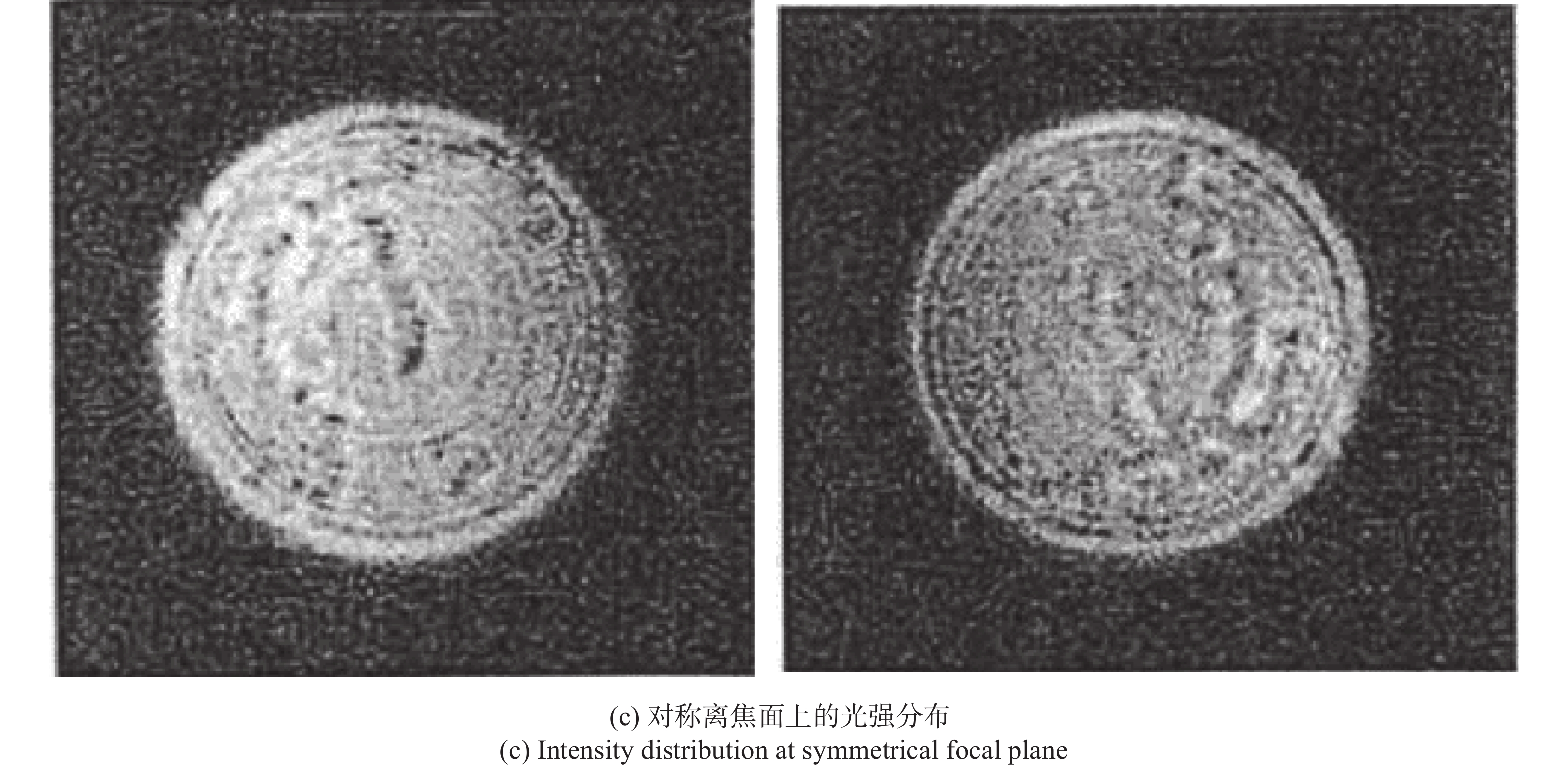
由于这种基于斜率的波前传感器在进行自适应光学波前矫正时,需要进行复杂的数学运算。当湍流变化剧烈时,其矫正精度就会受到影响,严重时自适应光学系统甚至会停止工作。1987年,F.Roddier[16]依据对称的离焦面上的光强分布与畸变波前的曲率有联系,得到波前的曲率,称这种波前传感器称为曲率传感器,如图6所示。由于这种方法中光强与曲率满足泊松方程,而薄膜型与压电型变形镜中镜面变化和控制信号也满足泊松方程,故可以将得到的曲率信号直接作用到变形镜上,减少了数学运算,提高了系统的带宽。相比于Hartmann-Shack波前传感器,曲率传感器能够使用更少的测量单元实现相同的精度,同时曲率波前传感能够调整探测精度,对于入射光瞳强度不均匀不敏感,能够实现更大的动态范围。由于这种曲率的波前传感其不需要复杂的数学计算与对入瞳光强分布不敏感的特性,相对于Hartmann-Shack波前传感器来说,是更加适合应用于镜面视宁度的检测之中的 。但是要注意的是,如果镜面湍流变化过于快速,这将导致这种曲率波前传感器的测量精度会受到影响,使入射波前的高频信息丢失。


图 6 曲率波前传感器
Figure 6. Curvature wavefront sensor
-
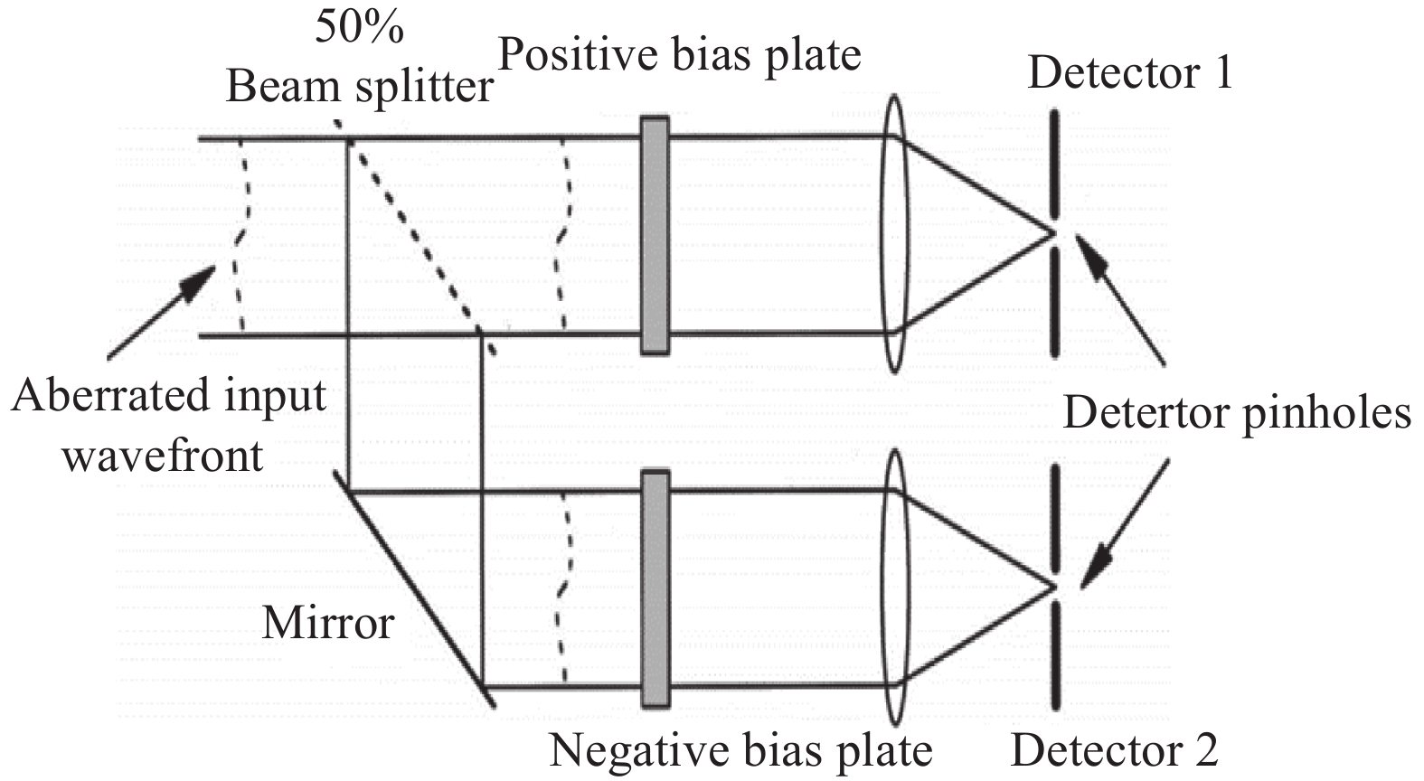
波前传感器可以分为平面载波和球面载波两种方法。平面载波制作全息图的原理是利用参考平面波与带有不同畸变模式的平面波在全息材料上进行干涉形成全息图。2000年,牛津大学的Neil等基于全息术提出了一种新型的波前传感技术[17-19]。这种波前传感器的基本原理类似与用模式法进行波前检测的Hartmann-Shack波前传感器,如图7所示。入射光通过两个具有相同偏置大小且正负相反的位相板,如果入射光存在该模式的成分,就会在两个探测器上形成亮度不一样的光斑。在小像差与低阶模式的情况下,两个探测器的相对光强和输入波前该模式的系数成线性关系。通过对输出光强的观察就能够确定入射波前该模式的系数,从而来得到整个波前形状。并且,全息图具有空间复用性,能够将不同模式的全息图复用到同一个全息图中,提高了系统的紧凑性。
之后,美国空军研究院激光研究中心Anderson[20]等对这种波前传感器进行了更加深入的研究,提出了球面载波的方法,并利用位置敏感元器件,最终实现了高达15 kHz的波前探测。Gladysz[21]等将这种波前传感器应用于激光通信中,补偿由湍流的影响而产生波前畸变,针对深空、自由空间和水下三种情况分别提出了波前传感算法和模型的改进,其中在全息波前传感器上使用不同模式拟合的结果如图8所示。Byoungho Lee[22]等深入研究了全息光学元件中像差对于图像质量的影响,提出了一种基于波动光学的计算全息方法,有效的降低了全息显示中像差的影响。我国对这种全息波前传感器的研究起步是比较晚的,姚凯男[23]提出了将全息波前传感器应用于自适应光学中,并做了大量的模拟仿真和数据处理工作,在一块21促动器的反射镜上成功搭建了平台,验证了理论上的正确性。程静欣[24]等针对全息波前传感器中的高阶衍射,提出了强度调制的方法,消除了高阶衍射中的干扰光,并普遍适用于其他二元光学元件。
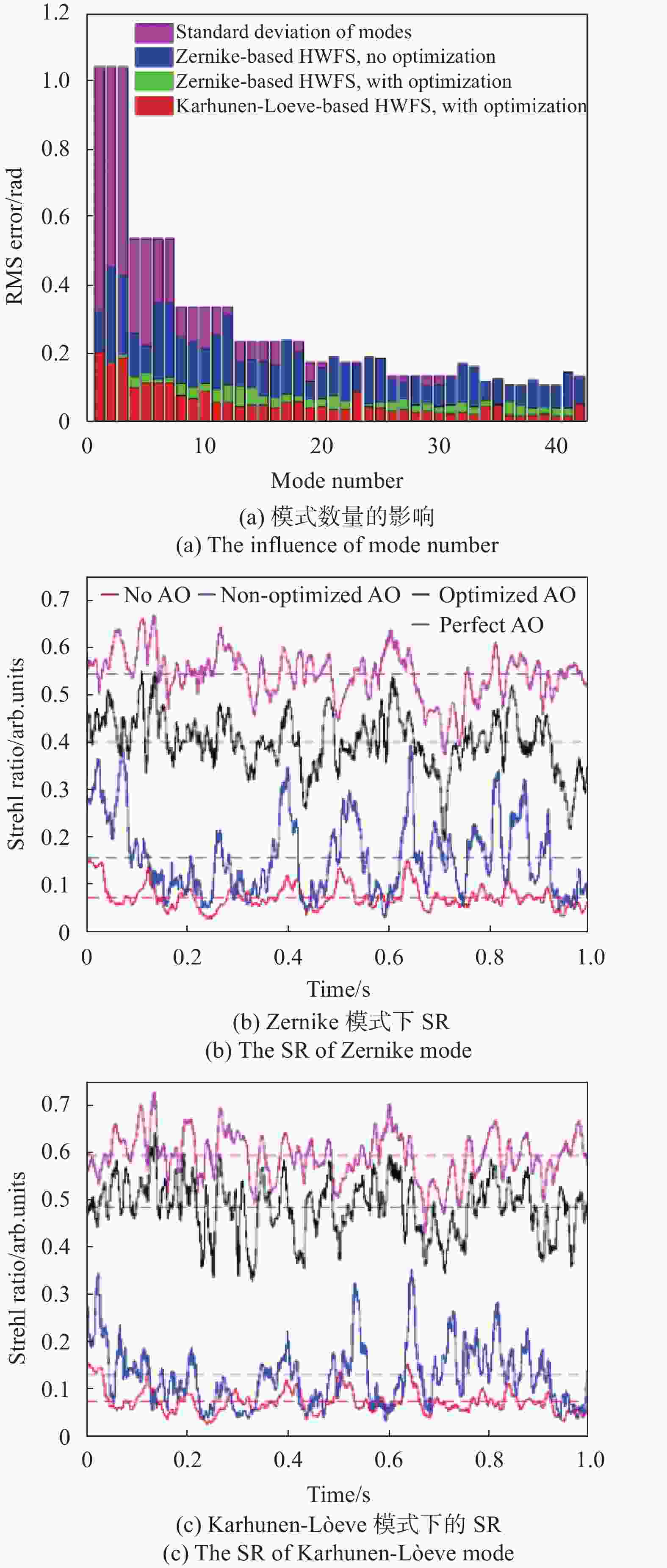
全息波前传感器与Hartmann-Shack波前传感器相比,由于其不需要计算复杂的波前重构矩阵,所以具有比传统波前传感器更高的带宽,能够达到15 kHz。但是,这种波前探测器的精度会受到光斑位置等因素的影响,只能够达到λ/50的程度。全息波前传感器不需要将波前划分为子波前,这对波前变化剧烈的场景具有更强的适应性。在自适应光学之中,由于全息波前传感器这种大带宽的特性,有望在将来实现在快速变化与极端情况下的波前检测与矫正。但是,这种全息波前传感器存在模式间串扰的问题,尤其是大像差与多模式的情况下。尽管可以通过选择畸变模式的数目与优化光路设计来减小这种模式串扰,但是面对复杂场景时,仍然要考虑这种影响。Zepp等对采样探针尺寸与偏置相差强度等参数的研究,对比Karhunen-Lòeve与Zernike模式在自适应光学中的矫正效果,有效的通过系统设计减小了模式间的耦合[25]。Gavril'eva与Kseniya等提出了一种基于漫散射的傅里叶方法[26],并在实验中验证了能够有效解决模式间串扰的问题。此外,检测镜面口径的不断增加将导致高阶像差的分量加大,这将使本身对高阶像差存在难以探测问题的全息波前传感器的检测精度产生更大的限制。
由于全息波前传感器存在模式串扰的问题,由图9的单模像差标定曲线可以看到:在输入单模像差的情况下,非本模式输出仍然存在,这对于某些特定的模式更为严重。但这种串扰问题并不会改变测得模式系数的正负,所以在自适应光学中,这种模式间的串扰并不会对波面的矫正有太大的影响。但是,在湍流测量等非矫正领域,模式串扰仍然是一个重要的问题。随着其不断的发展,近年来,这种模式串扰问题才真正得到了解决。目前,将这种全息波前传感器应用到镜面视宁度的检测之中并没有太多深入的研究。但不可否认的是,将其应用在镜面视宁度的检测中是非常具有前景的。且随着模式串扰这个主要问题的解决,全息波前传感器应用于镜面视宁度检测的优势又增加了。
-
干涉仪作为最早应用到湍流检测中的手段,其基本原理与面形检测的原理类似,即检测理想面形与实际面形的偏差来得到视宁度。但使用干涉仪来测量视宁度存在两个主要的问题:响应速度和口径。诸如菲索型、泰曼格林型等传统干涉仪的响应速度与口径限制了其在湍流检测中的应用,由于这两个缺陷使其本身很难在湍流检测中得到应用。但是,全息术的出现给这种干涉技术在湍流检测等方面带来了新的活力。将计算全息技术(CGH)应、数字型的菲索干涉仪等全息术与干涉技术的结合使镜面湍流的检测多了一种选择。
剪切干涉仪作为干涉仪中特殊的一种,因为其结构简单,对环境不敏感等特点被广泛应用于自适应光学等波前检测应用场景上。目前已有的剪切干涉仪器可以根据剪切的方向将它们分为横向剪切、径向剪切、旋转剪切和反转剪切。或者根据剪切方式区分为平板剪切干涉仪、萨瓦偏光镜干涉仪、渥拉斯特棱镜干涉仪和光栅剪切干涉仪。
相移技术是干涉测量技术的一个重要技术。由于诸如傅里叶载频、最小二乘法等静态干涉数据处理的方法需要大量的数学运算,中高频信息丢失,这往往会影响系统的带宽。19世纪80年代提出了一种相移技术,这种技术不需要复杂的计算,只需要计算由于引入相移产生的方程组就能够得到波前的数据。由于相移技术的简便性,使其广泛应用于光学干涉检测技术中。引入相移的方法包括移动反射镜、移动衍射光栅、旋转偏振片等。相移技术的出现提高了干涉检测技术的精度,使剪切干涉仪应用于镜面视宁度检测上的检测精度进一步得到加强。
剪切干涉技术一直都是一个经久不衰的研究方向。国内的王佳[27]等利用这种光栅剪切技术实现了三维的位移技术,建立了三维位移量与莫尔条纹强度分布的精确解析关系,并利用圆环滤波器将非相关衍射级次的光滤除,实验验证了这种位移的测量方法测量平面内位移的最大绝对误差为4.8×10⁻³ mm, 平均误差为2.0×10⁻⁴ mm, 轴向位移的最大绝对误差为0.25 mm,平均误差为8.6×10⁻³ mm。周健彪[28]等深入研究了基于平行平板的横向剪切中的波前重建精度的问题,分析了不同条件下的重建精度与剪切比的关系与平行平板角度误差对于重建的影响;刘璐等[29]人系统分析了横向剪切干涉仪中光学系统和图像处理算法两个部分的误差来源,并基于Zemax与Matalb分析了加工误差与装调误差对于面形重构的影响。王单单[30]等针对玻璃墙的无损检测,提出了一种数字剪切散斑干涉技术,使用相移技术实现了玻璃墙缺陷位置与其空间位移梯度的检测。国外的Marija Strojnik[31]等将剪切干涉仪应用在微弱信号的检测中,设想利用旋转剪切干涉仪来实现太阳系附近行星的检测,证明了模拟恒星并不会产生条纹,只有模拟行星才会产生条纹;Masatoshi Imbe[32]等提出了一种空间轴向共路的剪切干涉仪,以此来得到自然光纵向的互相干函数;Luis García-Lechuga[33]等提出了利用平行相移径向剪切干涉仪产生的复杂条纹分析透明样品的干涉测量方法,实现了较少的相移次数就能够得到样品的数据。剪切干涉仪的不断发展促使着其在镜面视宁度检测上的应用优势不断增加。
因为干涉仪固有的限制,剪切干涉仪的带宽只能够达到1 kHz的量级,但是其检测的精度却能够达到λ/100的量级。在泰勒冻结湍流的假设下,格林伍德频率为100 Hz,即使这种剪切干涉仪的带宽只能在1 kHz的量级,但在镜面湍流的测量下,已经足够了。并且,这种波前测量比较容易实现,最简单的情况下只需要一个平行平板与探测器和激光光源就能够实现。对环境不敏感,测量的范围也较大,这在镜面湍流的测量中是非常具有前景的。对于镜面不断增大的现状,剪切干涉法也存在Hartmann-Shack波前传感器法光路过长的问题。同时,由于一次剪切只能够得到一个方向上的波前斜率,如果需要得到整个波前斜率,则需要在垂直方向上再进行一次剪切操作。
-
全息摄影术将全息术应用到观测和量化由温度变化与边界层引起的折射率梯度变化。James D.Trolinger于1977年将全息术引用到了湍流测量这一领域中[1],提出了全息干涉术来测量湍流,给科学家们关于湍流的测量提供了一个新的思路。并且,由于这种测量技术集合了全息术与干涉术的优点,形成了高效灵敏的新方案,这对于位相介质的测量无疑是一个里程碑式的节点。
研究入射光经过位相介质之后的畸变波前,是自适应光学等需要进行波前矫正技术所主要研究的内容。但有时候,研究位相介质本身是更加具有意义的。对于镜面视宁度的测量,如果知道了湍流元胞在其镜面上的分布、大小、流速,对于加工检测与系统集成而言,是具有更大的指导意义的。传统成像的方法只能够进行二维的成像,而全息摄影术这种技术则是能够还原出物体的三维立体图,对于观测与量化湍流来说,更加具有直观性。
纹影成像作为一种二维的检测方法,可以认为是全息粒子测速的一次成像结果。纹影成像[34]是一种研究空气动力学、流体力学与热交换等一大重要的工具,将其应用于湍流的检测成像之中是完全可行的。如图透射式与反射式等传统的纹影成像系统由于是对三维流场的像面叠加,只能够进行一些定性的观测。聚焦纹影系统的出现使对特定区域流场的成像成为了可能。
由于流场区域内的折射率随空间位置的变化而变化,通过流场的光会在一定程度上偏离原来的方向。纹影成像的方法就是测量光线经过流场的偏折角来分析流场的特性,这在像面的表征就是像的灰度与背景灰度的差异。传统的透射式和反射式系统由于在像面处的图像是流场图像的三维投影,不能进行定量的测量,其中刀口的存在是为了切割点光源的像来提高光线偏折角的灵敏度。有别于传统的纹影成像系统,聚焦纹影成像使用源格栅和刀口栅来切割光源,并使用聚焦透镜来对特定区域内的流场进行成像。这种聚焦式的纹影成像系统使利用纹影成像来进行定量测量成为了可能,但是,受限于菲涅耳透镜等光学元件的加工限制,很难对2 m以上的大区域流场进行测量,于是便提出图10(d)所示的基于LED阵列的测量系统。通过对LED阵列的调整与源格栅的拼接,是能够实现超大区域流场测量的,这种方法对于流场的测量如图11所示。这种聚焦纹影成像的方法理论上是全息粒子测速的一个截面图,是一种二维成像的方法。
对于流场粒子的测速,热风枪测速仪和激光多普勒测速都仪能够在流场中进行单点测速或者是扫描进行面测速,但目前不能够实现三维测速。全息粒子测速是流场研究的一个重要技术。早在1977年,James D. Trolinger[1]就将全息干涉引用到了空间流体的成像中,提出了双曝光全息干涉术,并证明了这种技术具有极高的灵敏度。Trolinger的这篇文章开启了对湍流等流体可视化测量的新篇章。
Trolinger构建的全息双曝光测量系统如图12所示。HeNe激光器A发出的光通过双Q开关红宝石激光器C后,通过一个扩束器与透镜后变成一个准直光照射在湍流等感兴趣的流体区域中。湍流元胞的散射光与入射光干涉形成全息图被记录在了J处。重现时将全息记录材料放在H处,通过调焦探测器就能够对一定区域的湍流进行成像。重现系统中G是光程的补偿镜,主要用于重建时的光程补偿。之所以要用两个激光器是因为Trolinger时代激光器的输出带宽限制,需要用双Q开关红宝石激光器C进行选频并产生脉冲激光。通过在全息记录材料上叠加脉冲间隔的全息干涉图,就能够得到流体中元胞的速度场。需要注意的是,两次干涉的时间如果太短则观测不到湍流的运动,太长的话则容易受到外界因素的影响,这是需要权衡的一点。由于元胞的散射光可能会很微弱,所以这种测量的方法只能够捕捉到较大元胞的轮廓,如果需要更加精密的测量还需要另外的一种方法。利用这种方法对流体的成像效果如图13所示。
全息粒子测速是对于Trolinger测量装置的一种改进,Hui Meng[35]等研究了全息粒子测速在湍流相干结构中的重要作用,利用全息粒子测速得到了简单涡流场的瞬时三维速度矢量场,证明了这种方法的可行性,其记录装置与重建装置如图14所示。由于湍流等流体本身是透明的,散射光可能会很微弱,需要利用粒子或者染料来使湍流可视化。扩束后的激光打经过掺杂有粒子的湍流中,发生散射,从而与参考光在全息相机上发生干涉,并被全息相机所记录,一定时间间隔内再次进行干涉记录,便得到了湍流运动后的图像。重建时,将得到的全息图放置在三维调整机构上,因为CCD等光电探测器只能够成二维图像,所以需要调整全息图的位置来实现探测器的调焦,从而以此得到湍流不同切面的图像,反演出整个湍流的视图。通过相关运算,能够得到相应截面处的粒子速度,从而来表征湍流不同位置的流场速度。
相对于Hartmann-Shack波前探测器或者是全息波前传感器来说,这种全息粒子测速技术从位相介质可视化的角度来衡量与量化湍流对于视宁度的影响,更加具有直观性,对于研究湍流的相关结构等都具有重要的意义。只有得到记录全息图后才能进行下一步的数据处理,这是限制其应用的一大重要原因。此外,这种全息粒子测速技术对于光路的要求是非常严格的,对于光路上存在的装配误差或者是相关光学系统存在的像差容忍是很低的。并且由于整个三维测速的精度与标记粒子的浓度相联系起来,但是粒子浓度增加的情况下会增加散粒噪声。现有的测速粒子尺寸能够达到100 nm的级别,三维可分辨尺寸为1 μm,速度场的测量可分辨率为0.5 mm。尽管从分辨率上来说,达不到一维与二维等方法,但这种三维成像的方法能够以更加直观的方法对整个镜面尺寸的湍流进行成像,这对于系统评估等应用是具有很大价值的。相对的是,这种测量装置的结构较为复杂,在要求数据实时处理的场景中并不能得到应用。而且,这种全息粒子测速法会受到被检镜面口径的影响,随着被检尺寸的不断增加需要的全息图尺寸也会在一定程度上加大。
对于全息粒子测速的研究在Trolinger提出双曝光全息干涉术后就得到了快速的发展。国内的孙桂林[36]等提出了使用全息术来测量三维湍流;罗锐[37]等在微细流场中使用全息荧光粒子来进行三维测速,将荧光粒子图像测速技术和全息粒子图像测速相结合,改进了微流场中的粒子测速技术;赵攀杰[38]等搭建了一套高速显微散焦粒子图像三维测速系统,对不同通道进行了实验,通过实验与理论计算证明了该系统在与粒子测速应用中的可行性;李晓辉[39]等分析了不同粒子测速的优缺点,深入阐述了层析粒子测速的原理与发展,重点阐述了在层析粒子测速中不同因素对于测速的影响,为今后的层析粒子测速发展方向提供了一定的参考。Scott Simmons[40]等系统的总结了全息粒子测速的优点,讨论了这种技术的不同应用以及其困难,并基于其难点提出了一些可行的解决方案; Tomoyoshi Shimobaba [41]等基于深度神经网络算法对全息粒子测速图像进行重建来获得测速粒子的体积,并得到这种重建方法的重建效率要比传统的基于衍射的方法要更高。由于这种全息粒子测速没有做到实时的数据处理,在一些应用上是很难进行开展的,所以这种技术在现在的研究主要应该是集中在如何实现这方面。
-
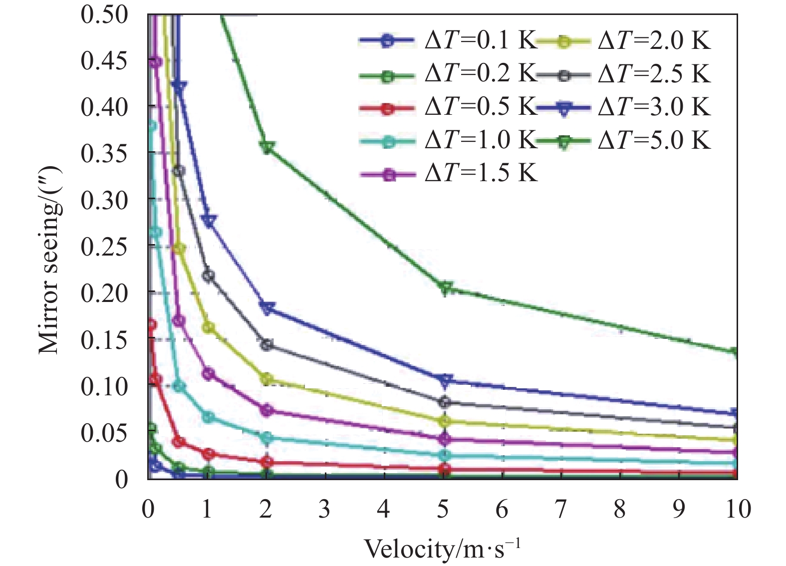
镜面视宁度很大程度上是温度变换导致的。当温度变换快速时,镜面上的温度会滞后于环境温度,当镜面与环境之间的温差达到一定程度时就会在发射面上形成一层空气扰动,这会导致镜面视宁度变差。解决这种热扰动的方法有两种:一是控制镜面温度,使其和环境温度一致;二是在平行与镜面的方向上吹风,从而在镜面上形成“气刀”,从而抚平空气扰动。镜面视宁度与温度紧密的联系在一起,所以测量镜面上的温度分布很大程度上是能够直接表征镜面视宁度的分布的。国内的夏勇波[42]等针对AIMS望远镜主镜温度分布,利用软件构建了图15所示的温度场分析模型,分析得到了如图16与图17所示的表征镜面视宁度的温度场分布与镜面视宁度分布。

在软件仿真中构建的分析模型如图15所示,通过将镜面与空气的接触上表面设置为流固耦合面进行分析,空气处设置为零压力,并进行了一些其他设置。将镜面与水平地面之间的夹角设置为观察角,分析不同观察角的镜面温度场分布,其结果如图16所示。与其他的一些镜面视宁度的检测装置相比,这种温度场的检测装置不需要复杂的结构,只需要得到镜面上的温度场就能够得到整个镜面视宁度的分布。精度为0.1°的测温设备,对于视宁度的影响为0.038"。如果是面形的加工检测这种需要高精度的检测结果,那么就需要更高精度的温度检测设备。对于系统的集成检测来说,精度不高的温度检测设备就能实现较好的可视化检测。

随着望远镜等仪器通光口径的不断加大,单一镜面望远镜已经不能满足人们的需求了。因此,拼接镜面成了人们对于大口径望远镜的另一种选择。由于拼接镜面起伏的包络会对光轴方向上的测量方法产生影响,降低各种方法的检测精度,所以上述的一维、二维与三维检测方法中的光学检测方法应用于拼接镜面视宁度检测上是会受到一定限制的。但这种基于计算流体力学得到镜面温度场的方法因为不会受到该因素的影响,在拼接镜面望远镜上的镜面视宁度检测上受到广泛的关注。TMT、GMT等30 m级别的拼接望远镜采用这种方法对镜面视宁度进行了一定的研究,取得了较好的效果。
国外的Bar[43]等在美国国家天文台上详细的研究了1.8 m镜面上的湍流,使用两种方法得到不同温度下的镜面干涉图,证明了镜面视宁度符合Kolmolgorov 湍流假设,为温度场法测量镜面视宁度奠定了理论基础;Melisa Tallis[44]等研究了镜面视宁度在自适应光学设备中的影响,通过对双子座行星成像仪三年内的系外行星观测数据的研究,得到了当镜面温度与外界温度平衡时观测效果最佳,不平衡时积分湍流会一定程度上偏离Kolmolgorov 湍流,为镜面视宁度的产生提供了依据;Pazder[45]等利用Matlab建立了一套分析镜面与圆顶周围温度差异对于成像的影响的仿真算法,成功利用软件在流体力学方面实现了镜面湍流影响的可视化。张俊[46]深入研究了镜面温度对于镜面视宁度的影响,提出了用于大口径蜂窝镜面温度控制研究的单蜂窝单元假设,并利用计算流体动力学方法和有限元方法对4 m蜂窝镜的温度场和热变形进行了计算,为将来国内大口径镜面温度控制设备提供了理论基础。刘祥意[47]基于热控理论,对4 m SiC轻量化主镜的望远镜主镜热控系统进行较详细的研究和设计,利用热控的缩比实验验证热控方案的可行性,这对减小镜面视宁度的系统设计具有指导意义。
-
早期望远镜因为通光口径较小的原因,可以忽略镜面湍流的影响。但随着人们对于望远镜通光口径尺寸的不断增大,当其超过当地的镜面湍流尺度时,就必须得考虑其带来的影响,因此镜面视宁度不管是在加工检测与系统应用集成检测之中都变得越来越重要。随着TMT、GMT等30 m级别望远镜项目的不断开始,可以说镜面视宁度检测技术的发展已经是不可或缺的了。目前对于镜面视宁度检测方法的研究是比较少的,今后相关的工作应当是集中在研究可应用与镜面视宁度的检测方法。同时,如何在不影响系统光路的前提下实现镜面视宁度检测的普遍性、实时性、结构简单性,也是今后研究的一个重点。
国内相较美国等国家开始对大口径望远镜进行相关研究的时间是比较晚的。目前,国内已建成的最大口径光学望远镜是4 m级别的LAMOST。对于LAMOST来说,长达60 m光路所导致的圆顶视宁度是其主要的问题[48],并且由于其不成像,所以在镜面视宁度检测方法方面上的研究是不充分的。与此同时,国内的2 m级别的大口径望远镜相比于其他国家来说也甚少[49],这也是镜面视宁度检测这方面研究缺乏的一个原因。随着国内大口径望远镜的相继规划建设,对于镜面视宁度检测也应当加以重视。
表1从优缺点与可达到的技术指标综合对比了可应用于镜面视宁度检测的不同技术,能够给进行镜面视宁度检测时选用方法提供参考。表2列举了一些已经建成或者是在建望远镜所采用的镜面视宁度检测方法。文章从一维到三维的角度出发,分别对自准直仪法、曲率/斜率波前传感器法、全息波前传感器法、剪切干涉仪法、全息粒子测速法与温度场法这几种可应用于镜面视宁度检测的几种方法进行了综述。从复杂性的角度出发,自准直仪法是最容易实现的一种方法,但是这种方法往往存在测量区域有限的限制,很难在快速变化的湍流中实现全面的测量。从测量精度出发,基于曲率/斜率波前传感器与全息波前传感器的方法往往能够实现高精度的测量,但是如何在这种二维投影的方法中去除镜面本身面形缺陷还是需要进行考虑的。从直观的角度来看,三维测量方法中全息粒子测速与温度场的方法能够提供一个较为直观的表达,但是其测量精度会受到限制。从数据处理的角度来看,全息波前传感器这个21世纪新出现的方法能够提供较为高的带宽,但是精度问题仍然是其存在的主要问题。在面形加工检测与系统集成检测等应用中,需要对成本、精度要求与环境等因素进行综合考虑。文章对于不同方法的综述能够为今后视宁度检测等提供指导作用,给与从事相关研究的工作者帮助。
表 1 可应用于镜面视宁度检测的不同方法对比
Table 1. Comparison of different methods that can be applied to the detection of mirror seeing
Method Classification Advantage Disadvantage Performance Tradition Same path, interference - High cost, slow response - 1D Autocollimator Simple structure Limited measurement range Resolution 0.0003 nPSS 2D Hartmann-Shack WFS/Slope WFS Larger measurement range than 1D Complex mathematics and lowbandwidth
in slope WFS; the former can’t work
in moderate turbulenceAccuracy λ/100, bandwidth 10 kHz Holographic WFS No complex mathematics, simple structure, can work in moderate turbulence Larger error in large aberration,
high modeAccuracy λ/50, bandwidth 15 kHz Shear interference Simple structure, compact system,
low environmental sensitivityAdjust device for orthogonal wavefront Accuracy λ/100, bandwidth 1 kHz Schlieren imaging Visible flow fieldlarge
measurement rangeLimited accuracy - 3D Holographic particle velocimetry 3D imaging, intuitive way Complex device, offline processing,
low accuracy3D resolution 1 μm, velocity field resolution 0.5 mm Temperature field Simple and easy to operate,
real-time processingLower accuracy than optic 0.1° sensor accuracy equivalent to mirror seeing 0.038″ 表 2 不同望远镜镜面视宁度的检测方法
Table 2. Detection method of the mirror seeing of different telescopes
Telescope Diameter/m Method Result AIMS 1 Temperature field [50] 0.3″(FWHM) GREGOR 1.5 - CLST 1.8 ≤0.05″(FWHM) ISMAT 2.5 - EST 4 ≤0.05″(FWHM) DKIST 4.24 <0.02″(FWHM) SUBARU 8.2 Camera in main focus 0.7″(FWHM) KECK II 10 Scintillation counter 0.3″(FWHM) GMT 25.4 - 0.9988 (0.5 μm) nature control (nPSS)[51] TMT 30 Temperature field [45] 0.9965 (lowest) (nPSS)
Review on the measurement methods of mirror seeing of large-aperture telescope
-
摘要: 望远镜分辨率和集光能力与其口径成正比。随着人类对于望远镜分辨力要求的日渐严格,望远镜的镜面尺寸也在不断的增加。镜面尺寸的不断加大,使镜面视宁度变得越来越重要。镜面视宁度主要是指由于镜面表面的湍流所导致的像质下降。当镜面尺寸超过当地大气湍流尺度时,就不得不考虑这一因素对于成像或者加工的影响。系统的工作环境在一定程度上会影响镜面视宁度,所以镜面视宁度对于集成检测过程也有重要的意义。因此,为了提高镜面加工的面形精度,检测系统的集成效果,必须精确测量仪器的镜面视宁度,从而为其加工检测和应用集成提供判断。文中从原理、研究现状以及在镜面视宁度上的应用三个方面出发,阐述了一维检测(自准直仪法等)、二维检测(斜率/曲率法、全息波前传感法和剪切干涉法等)、三维检测(全息粒子测速法与温度场法等)。通过介绍面向不同场景与检测要求的检测方法,对镜面视宁度的检测具有很好的指导意义。Abstract: The resolution and light collection ability of telescope were directly proportional to its aperture. With the increasingly strict requirements of human beings for the resolution of telescopes, the size of telescope mirrors would be also increasing. With the increasing size of the mirror, the mirror seeing became more and more important. Mirror seeing mainly referred to the degradation of image quality caused by turbulence on the mirror surface. When the mirror size exceeded the local atmospheric turbulence scale, we had to consider the influence of this factor on imaging or processing. The working environment of the system would affect the mirror seeing to a certain extent, so the mirror seeing was also of great significance to the integrated detection process. Therefore, in order to improve the surface accuracy of mirror processing and the integration effect of the detection system, it was necessary to accurately measure the mirror seeing of the instrument, so as to provide judgment for its processing detection and application integration. In our work, one-dimensional detection (autocollimator method, etc.), two-dimensional detection (slope/curvature method, holographic wavefront sensing method and shearing interference method, etc.) and three-dimensional detection (holographic particle velocimetry and temperature field method, etc.) were described from three aspects: principle, research status and application in mirror seeing. By introducing the detection methods for different scenes and detection requirements, it had a good guiding significance for the detection of mirror seeing.
-
Key words:
- mirror seeing /
- turbulence /
- test method /
- application
-
表 1 可应用于镜面视宁度检测的不同方法对比
Table 1. Comparison of different methods that can be applied to the detection of mirror seeing
Method Classification Advantage Disadvantage Performance Tradition Same path, interference - High cost, slow response - 1D Autocollimator Simple structure Limited measurement range Resolution 0.0003 nPSS 2D Hartmann-Shack WFS/Slope WFS Larger measurement range than 1D Complex mathematics and lowbandwidth
in slope WFS; the former can’t work
in moderate turbulenceAccuracy λ/100, bandwidth 10 kHz Holographic WFS No complex mathematics, simple structure, can work in moderate turbulence Larger error in large aberration,
high modeAccuracy λ/50, bandwidth 15 kHz Shear interference Simple structure, compact system,
low environmental sensitivityAdjust device for orthogonal wavefront Accuracy λ/100, bandwidth 1 kHz Schlieren imaging Visible flow fieldlarge
measurement rangeLimited accuracy - 3D Holographic particle velocimetry 3D imaging, intuitive way Complex device, offline processing,
low accuracy3D resolution 1 μm, velocity field resolution 0.5 mm Temperature field Simple and easy to operate,
real-time processingLower accuracy than optic 0.1° sensor accuracy equivalent to mirror seeing 0.038″  下载: 导出CSV
表 2 不同望远镜镜面视宁度的检测方法
Table 2. Detection method of the mirror seeing of different telescopes
Telescope Diameter/m Method Result AIMS 1 Temperature field [50] 0.3″(FWHM) GREGOR 1.5 - CLST 1.8 ≤0.05″(FWHM) ISMAT 2.5 - EST 4 ≤0.05″(FWHM) DKIST 4.24 <0.02″(FWHM) SUBARU 8.2 Camera in main focus 0.7″(FWHM) KECK II 10 Scintillation counter 0.3″(FWHM) GMT 25.4 - 0.9988 (0.5 μm) nature control (nPSS)[51] TMT 30 Temperature field [45] 0.9965 (lowest) (nPSS)
下载: 导出CSV
-
[1] Trolinger J D. Diagnostics of turbulence by holography [J]. Advances in Laser Technology for the Atmospheric Sciences, 1977, 18(2): 161-166. [2] Dekens F G, Kirkman D, Chanan G A, et al. High-speed seeing measurements at the Keck Telescope[C]//Proceedings of SPIE, 1994, 2201. [3] Miyashita A, Oschmann J M, Takato N, et al. Statistics of the weather data, environment data, and the seeing of the subaru telescope[C]//Proceedings of SPIE, 2004, 5489: 207. [4] Yang Fei, An Qichang, Zhang Jing, et al. Seeing metrology of large aperture mirror of telescope [J]. Optics and Precision Engineering, 2017, 25(10): 2572-2579. (in Chinese) [5] Yellowhair J, Burge J H. Analysis of a scanning pentaprism system for measurements of large flat mirrors [J]. Appl Opt, 2007, 46(35): 8466-8474. doi: 10.1364/AO.46.008466 [6] An Qichang, Wu Xiaoxia, Zhang Jingxu, et al. Detection method of mirror seeing based on curvature/slope hybrid sensing [J]. Infrared and Laser Engineering, 2021, 50(7): 20200419. (in Chinese) doi: 10.3788/IRLA20200419 [7] Shatokhina I, Hutterer V, Ramlau R. Review on methods for wavefront reconstruction from pyramid wavefront sensor data [J]. Journal of Astronomical Telescopes, Instruments, and Systems, 2020, 6(1): 010901. [8] Zhang H. Research on wavefront testing of large aperture space optical systems based on subaperture scanning technology[D]. Changchun: Graduate School of Chinese Academy of Sciences(Changchun Institute of Optics, Fine Mechanics and Physics, Chinese Academy of Sciences), 2017. (in Chinese) [9] Zhang Yong, Yang Dehua, Cui Xiangqun. Measuring seeing with a Shack-Hartmann wave-front sensor during an active-optics experiment [J]. Appl Opt, 2004, 43: 729-734. [10] Ilya Galaktionov, Alexander Nikitin, Julia Sheldakova, et al. Shack-Hartmann sensor with B-spline approximation technique[C]//Proceedings of SPIE, 2022, 11987: 119870K. [11] Noam Sapiens. 2D reverse Shack-Hartmann ocular refraction measurement[C]//Proceedings of SPIE, 2021, 11623: 116232A. [12] Rukosuev A L, Belousov V N, Nikitin A N, et al. Laboratory simulation of atmospheric turbulence in the problem of correcting laser radiation wavefront distortions by using a fast adaptive optical system [J]. Izvestiya, Physics of the Solid Earth, 2021, 57(5): 789-794. doi: 10.1134/S1069351321050165 [13] Wu Wei, Luo Zirong, Yu Naihui, et al. Computer-aided alignment method based on Shack-Hartman sensor [J]. Acta Optica Sinica, 2020, 40(20): 2022001. (in Chinese) [14] Han Yanna, Hu Xingqi, Dong Bing. Iterative extrapolation method to expand dynamic range of Shack-Hartman wavefront sensors [J]. Acta Optica Sinica, 2020, 40(16): 1611004. (in Chinese) [15] Qian Siyu, Liu Peng, Jing Wenbo, et al. Study on the method of spot centroid detection for optimizing the Shack-Hartmann wavefront sensor [J]. Journal of Changchun University of Science and Technology (Natural Science Edition), 2020, 43(4): 19-24. (in Chinese) [16] Roddier F. Curvature sensing and compensation: a new concept in adaptive optics [J]. Applied Optics, 1988, 27(7): 1223-1225. doi: https://doi.org/10.1364/AO.27.001223 [17] Neil M A A, Booth M J, Wilson T. New modal wave-front sensor: a theoretical analysis [J]. Journal of the Optical Society of America A, 2000, 17(6): 1098-1107. doi: 10.1364/JOSAA.17.001098 [18] Booth M J, Neil M A A, Wilson T. New modal wave-front sensor: application to adaptive confocal fluorescence microscopy and two-photon excitation fluorescence microscopy [J]. Journal of the Optical Society of America A, 2002, 19(10): 2112-2120. [19] Neil M, Booth M J, Wilson T. Closed-loop aberration correction by use of a modal Zernike wave-front sensor. [J]. Optics Letters, 2000, 25(15): 1083-1085. doi: 10.1364/OL.25.001083 [20] Ghebremichael F, Andersen G P, Gurley K S. Holography-based wavefront sensing [J]. Applied Optics, 2008, 47(4): 62-69. doi: 10.1364/AO.47.000A62 [21] Gladysz S, Zepp A, Segel M, et al. Wavefront sensing for terrestrial, underwater, and space-borne free-space optical communications[C]//Laser Communication and Propagation through the Atmosphere and Oceans X, 2021, 11834: 118340F. [22] Byoungho Lee, Seung-Woo Nam, Dongyeon Kim. Aberration correction in holographic displays[C]//Proceedings of SPIE, 2022, 12025: 120250A. [23] Yao K N. Study on holographic wavefront sensing method and dynamic holographic adaptive optics[D]. Changchun: Graduate School of Chinese Academy of Sciences(Changchun Institute of Optics, Fine Mechanics and Physics, Chinese Academy of Sciences), 2015. (in Chinese) [24] Cheng Jingxin, Yang Haibo, Li Man, et al. Suppression of high order diffraction in holographic wave-front sensor [J]. Acta Optica Sinica, 2021, 41(10): 1009001. (in Chinese) [25] Zepp A, Gladysz S, Stein K, et al. Simulation-based design optimization of the holographic wavefront sensor in closed-loop adaptive optics [J]. Light: Advanced Manufacturing, 2022, 3: 1-13. [26] Venediktov V Y, Gorelaya A, Fedorov E, et al. Approaches to cross-talk noise reduction in modal holographic wavefront sensors[C]//Optical Sensing and Detection, 2018, 10680: 106802O. [27] Wang Jia, Liu Rongming, Wang Jiachao, et al. Measurement of three-dimensional displacements by radial shearing interfero-meter [J]. Acta Physica Sinica, 2021, 70(7): 20201451. (in Chinese) [28] Zhou Jianbiao, Yang Zihan, Liang Yanmei. Study on wavefront reconstruction accuracy of parallel plate lateral shearing interferometer [J]. Journal of Optoelectronics·Laser, 2020, 31(9): 921-927. (in Chinese) doi: 10.16136/j.joel.2020.09.0121 [29] Liu L. Comprehensive analysis of radial shear interference errors[D]. Xi’an: Xi’an Technological University, 2019. (in Chinese) [30] Wang Dandan, Gao Yan, Li Weixian, et al. Digital shearing speckle pattern interference non-destructive testing of glass curtain wall defects [J]. China Measurement & Test, 2022, 48(4): 29-34. (in Chinese) [31] Marija Strojnik. Rotationally shearing interferometry in the recovery of faint signals[C]//Proceedings of SPIE, 2021, 11830: 1183007. [32] Masatoshi Imbe. Spatial axial shearing common-path interfero-meter for natural light [J]. Appl Opt, 2020, 59: 11332-11336. [33] Luis García-Lechuga, Patricia Pérez-Luna, Victor H Flores, et al. Parallel phase shifting radial shear interferometry with complex fringes and unknown phase shift [J]. Appl Opt, 2020, 59: 2128-2134. [34] Wang Min, Xie Aimin, Huang Xunming. Preliminary study on direct schlieren technology [J]. Journal of Ordnance Equipment Engineering, 2020, 41(10): 244-248. (in Chinese) doi: 10.11809/bqzbgcxb2020.10.045 [35] Hui M, Hussain F. Holographic particle velocimetry: A 3D measurement technique for vortex interactions, coherent structures and turbulence [J]. Fluid Dynamics Research, 1991, 8(1-4): 33-52. doi: 10.1016/0169-5983(91)90029-I [36] Sun Guilin, Cong Zhen. Measurement of three-dimensional turbulence by holographic technique [J]. Laser & Optoelec-tronics Progress, 1995, 32(6): 31. (in Chinese) [37] Luo Rui, Sun Yanfei, Yang, Xianyong. 3-D holographic fluorescent particle image velocimetry for micro-fluidic measurements [J]. Journal of Engineering Thermophysics, 2006(3): 493-495. (in Chinese) doi: 10.3321/j.issn:0253-231X.2006.03.042 [38] Zhao P J. Study on the three-dimensional particle tracking velocimetry based on the defocusing microscopic image[D]. Hangzhou: China Jiliang University, 2016. (in Chinese) [39] Li Xiaowei, Wang Hongwei, Huang Zhan, et al. Research advances of tomographic particle image velocimetry [J]. Journal of Experiments in Fluid Mechanics, 2021, 35(1): 11. (in Chinese) doi: 10.11729/syltlx20190160 [40] Hussain F, Meng H, Liu D, et al. Advances in holographic particle velocimetry[C]//Proceedings of SPIE, 1993, 2005:11-16. [41] Tomoyoshi Shimobaba, Takayuki Takahashi, Yota Yamamoto, et al. Digital holographic particle volume reconstruction using a deep neural network [J]. Appl Opt, 2019, 58: 1900-1906. [42] Xu S, Xie Y, Xia Y, et al. Evaluation on mirror seeing for AIMS solar telescope[C]//The International Conference on Photonics and Optical Engineering, 2019, 11052: 110520O. [43] Barr L D, Fox J, Poczulp G A, et al. Seeing studies on a 1.8-m mirror[C]//Proceedings of SPIE, 1990, 1236: 492-506. [44] Tallis M, Bailey V P, Macintosh B, et al. Effects of mirror seeing on high-contrast adaptive optics instruments [J]. Journal of Astronomical Telescopes Instruments and Systems, 2020, 6(1): 1. [45] Pazder J S, Vogiatzis K, Angeli G Z. Dome and mirror seeing estimates for the Thirty Meter Telescope[C]//Proceedings of SPIE, 2008, 7017: 70170R. [46] Zhang J. Study on control methods of honeycomb mirror temperature and mirror seeing[D]. Chengdu: Graduate School of Chinese Academy of Sciences (Institute of Optics and Elec-tronics, Chinese Academy of Sciences), 2013. (in Chinese) [47] Liu X Y. Research on thermal control system of 4 m SiC lightweight primary mirror[D]. Beijing: University of Chinese Academy of Sciences, 2015. (in Chinese) [48] Li Rong, Shi Huli. Chen Zhiping. Thermal calculation and simulation of dome in LAMOST[C]//China CAE Enginee-ring Analysis Technology Annual Meeting and National Computer Aided Engineering, 2011. (in Chinese) [49] Zhang Jingxu. Overview of structure technologies of large aperture ground-based telescopes [J]. Chinese Optics, 2012, 5(4): 327-336. (in Chinese) doi: 10.3969/j.issn.2095-1531.2012.04.004 [50] Zhu Ran, Gu Bozhong, Xu Jieqian, et al. Thermal control technology of primary mirror of 2.5 m class solar telescope [J]. Acta Optica Sinica, 2018, 38(11): 1112001. (in Chinese) doi: 10.3788/AOS201838.1112001 [51] Bouchez A H, Angeli G Z, Ashby D S, et al. An overview and status of GMT active and adaptive optics[C]//Adaptive Optics Systems VI. International Society for Optics and Photonics, 2018, 10703: 107030W. -

 点击查看大图

图(18) / 表(2)
计量
- 文章访问数: 456
- HTML全文浏览量: 165
- PDF下载量: 59
- 被引次数: 0

