


-
近年来,随着低噪声、宽波段探测器的研制成功,被用于军事领域的高灵敏度红外探测系统,其工作波长逐步由7.7~10.3 μm扩展到8~12 μm。透射式光学成像系统由于材料吸收限制,已无法满足宽波段高灵敏度的需求。反射式光学成像系统具有工作波段宽、透过率高、体积小、质量轻等技术优点,可以很好地满足宽波段、高灵敏度的探测需求,但传统反射式光学成像系统存在子午视场小、不具备实入/出瞳,难以适配制冷型探测器冷光阑设计等技术缺点。
随着大面阵、高分辨率制冷型探测器的发展与广泛应用,对于光学系统的成像视场、成像性能要求越来越高。传统的反射式光学系统已难以满足矩形大视场或结构空间约束复杂的设计需求。相比于旋转对称的球面和非球面,自由曲面具有更高的设计自由度,通过引入自由曲面,光学系统可以在结构空间约束复杂的要求下实现更大的成像视场,并具备更优异的成像性能。
国内外许多学者对自由曲面离轴三反光学系统进行了研究[1-6],多采用两三个自由曲面实现设计,光学系统构型为一次成像矩形视场光路[2-3]或二次成像实入/出瞳线性视场光路[4],对于二次成像实入/出瞳矩形视场光路的设计报告较少。
参考文献[5]最近公布了一种二次成像的矩形视场光路,其工作波段8~12 μm,视场5°×3°,F数2.5;参考文献[6]设计了一套视场角4°×5°、F数为1.38的离轴三反光学系统。对于长波红外系统,较小的F数和更大的视场则更加实用化。另外,目前通用制冷型探测器的F数通常为2。文中给出了一种多视场快速数值迭代的求解方法,针对640×512@24 μm长波红外制冷型探测器货架产品,设计了一套离轴三反光学系统,仅含有一片自由曲面,光学系统焦距160 mm,工作波段8~12 μm,F数2,视场5.5°×4.4°,冷光阑效率100%。
-
国内外许多学者针对反射式光学系统的设计方法进行了研究,典型进展如下:(1)潘君骅等学者提出的基于赛德尔像差方程组的同轴反射式光学系统设计方法;(2) Takayuki N[7]等学者提出的利用二次曲面共轭点特征搭建光路,实现理想像点传递;(3) Tamer T. Elazhary[8]等学者推导了广义正弦条件,并以此构建了线性/二次场相关矢量像差方程,实现了面对称反射系统初始结构设计;(4)徐奉刚等学者将W-W方程用于同轴反射式光学系统初始结构的求解;(5) Tong Yang[2]等学者提出的基于构造迭代过程的设计方法实现了离轴反射式光学系统初始结构的求解;(6)美国OSD公司基于SYNOPSYSTM商业软件给出了从平面反射镜出发,设计离轴反射式光学系统的案例。
随着计算机硬件/软件计算能力的不断发展,基于数值迭代的设计方法将更适合在复杂约束下(尺寸包络、实入/出瞳、多视场)进行初始结构设计。
文中给出了一种基于像差方程的快速数值迭代计算方法,可以实现对多个视场进行求解。求解的基本过程如图1所示,该方法是一种近似优化的数值迭代方法,首先在中心视场下确定系统的初始结构参数,然后通过表面面形的可优化性,实现多视场初始结构的求解。
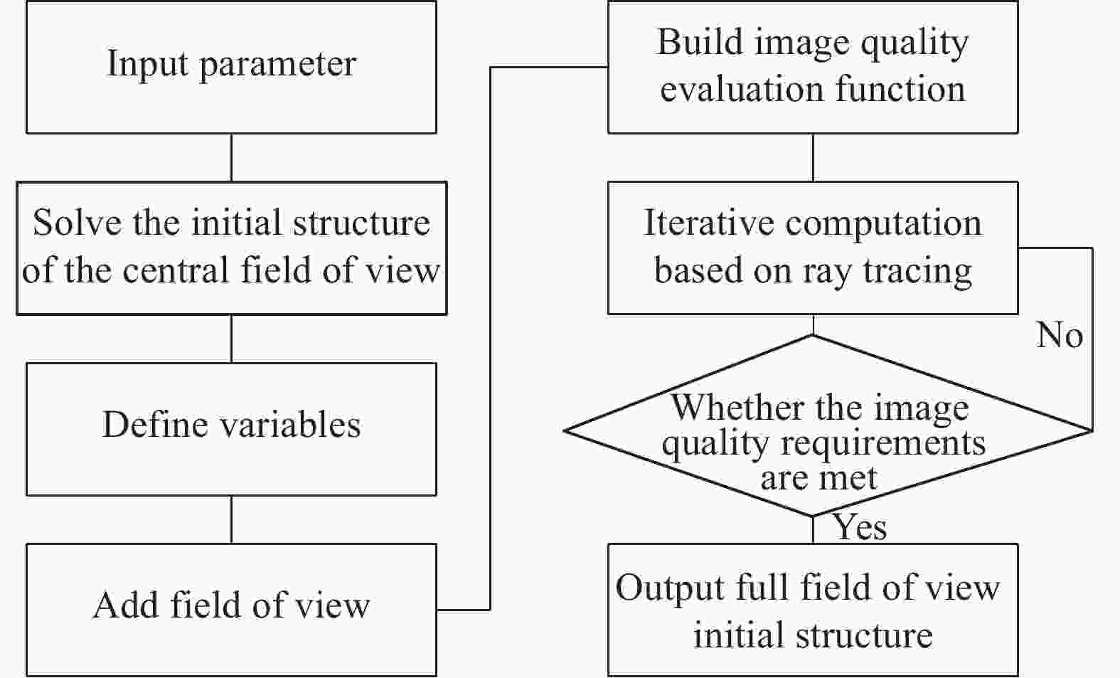
图 1 算法流程框图
Figure 1. Algorithm flow diagram
求解的具体步骤如下:
(a)设定输入参数,包括中心视场、口径、光阑离轴量等;
(b)中心视场的求解方法较多,可以参考二次曲面无像差点特征衔接设计方法[7]、二次场矢量像差方程设计方法[8]、偏微分方程设计方法[3]、或基于赛德尔像差方程的设计方法[9-10];2022年,许宁晏等学者对多种自由曲面的设计方法进行了整理归纳[11]。
以 Tamer T. Elazhary二次场矢量像差方程为基础,解算中心视场初始结构;Tamer T. Elazhary 推导了广义正弦条件(generalized sine condition,GSC)[8],并适用于非旋转对称系统。
$$ n(\Delta \vec{h} \cdot \hat{\rho})+n^{\prime}\left(\Delta \vec{h^{\prime}} \cdot \hat{\rho^{\prime}}\right)=Constant $$ (1) 式中:
$ n $ 、$n'$ 、$\Delta \vec{h}$ 、$\Delta \vec{h'}$ 、$\;\hat{\rho}$ 、$\;{\rho'}$ 分别为物方和像方介质折射率、视场以及孔径;$ Constant $ 为常量。以GSC为基础,进一步构建二次场矢量像差方程:
$$ {\rm{d}} W\left(P \vec{M} E, \Delta \vec{h^{\prime}}\right)=\left(\frac{n^{\prime}}{R^{\prime}}\right) \Delta \vec{h^{\prime}} \cdot P \vec{M} E+ Constant $$ (2) 式中:
$\Delta \vec{h}$ 、$\Delta \vec{h^{\prime}}$ 分别为物方和像方视场;$n^{\prime}$ 为像方介质折射率;$R^{\prime}$ 为出瞳参考球表面曲率半径;$ P \vec{M} E $ 为瞳孔畸变误差。(c)定义多视场下的迭代变量,包括间隔、曲率、面形等。为缩小数值迭代计算的时间,迭代变量为主次镜间隔、主次镜曲率以及三镜的面形,其中三镜面形采用XY多项式表达;
(d)添加视场,为了减少迭代优化时间,将三镜面形限定为关于Y轴对称,这样整个系统为面对称系统,仅在+X轴的两个象限添加视场即可;
(e)构建评价函数,评价函数为每个视场的像面光线散斑尺寸,在MATLAB中采用fmin函数实现多重结构下的评判处理;
(f)对初始结构的多个视场进行光线追迹,穷举变量,统计不同循环次数时的评价函数大小,寻找满足要求的初始结构;
(g)若满足像质要求,则输出结构参数;若不满足像质要求,程序中设定最大计算时间,超出计算时间后,自动返回最优初始结构及像质。
将上述步骤在MATLAB中编程实现,最后输出结果为光学设计软件CODEV支持的文件格式,方便在CODEV中做进一步的优化及评价处理。
-
探测参数如下:
(a)面阵:640×512;
(b)像元:24 μm×24 μm;
(c) F数:2;
(d)冷光阑距像面距离:25.7 mm。
光学系统设计参数如下:
(a)工作波段: 8~12 μm;
(b)焦距:160 mm;
(c) F数:2;
(d)视场:5.5°×4.4°;
(e)像质:全视场RMS<0.06λ (λ=9.11 μm)。
-
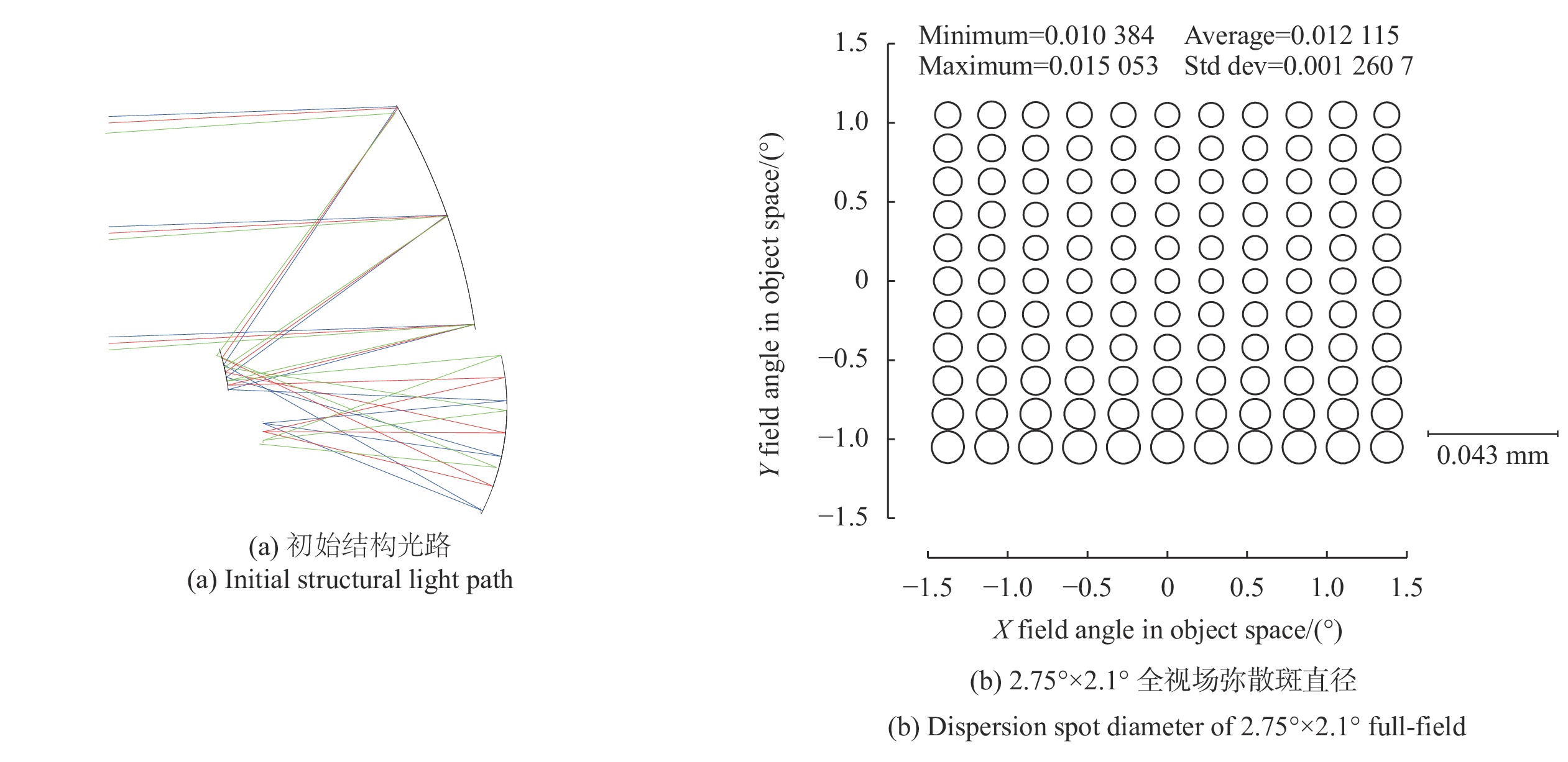
初始结构的计算主要满足尺寸约束、实入/出瞳、部分视场要求(初始结构设计采用全视场的一半),目的是为光学系统优化设计提供一个较好的优化起点,从而缩短光学设计周期。在构建初始结构时,选用二次成像构型,通过二次成像结构的几何关系对系统长度和后截距进行约束,从而实现100%冷光阑效率。
通过上述初始结构设计方法,求得初始结构如图2(a)所示,初始计算视场的弥散斑如图2(b)所示。
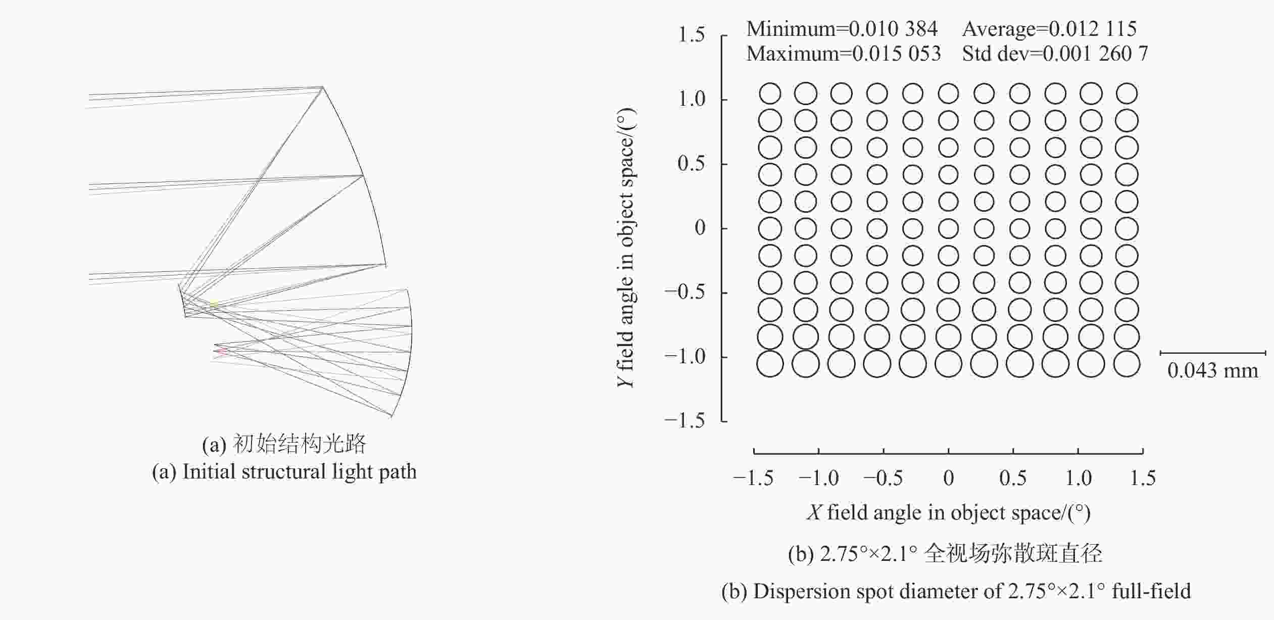
图 2 初始结构及像质
Figure 2. Initial structure and image quality
-
初始结构完成后,由于自由曲面的非对称性,需要联合更多的视场在光学设计商业软件中做进一步的优化,该设计采用CODEV软件优化。
在CODEV中,优化主要考虑全视场像质平衡、像质评价、面形检测、公差分析等方面。
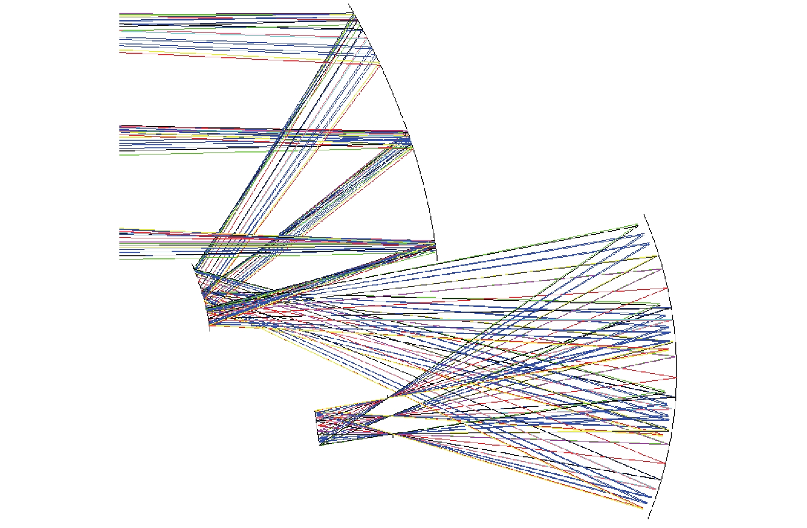
考虑到选择的自由曲面面形关于Y轴对称,因此在–X半轴添加视场视场。全视场像质平衡采用节点像差优化方法,该方法由K. Fuerschbach等学者[12]提出,通过平衡全视场的彗差和像散节点特征,逐步优化,优化过程如图3所示。首先利用彗差和像散的节点特征对全视场波前像差进行平衡优化,其次考虑加工/装调难度,逐步减少自由曲面的数量,最后再对波前像差进行平衡优化。最终优化完成后的光路如图4所示。其中主镜为凹的椭球面,次镜为凸的双曲面,三镜为XY多项式自由曲面并关于Y轴对称。

图 3 优化过程示意图
Figure 3. Schematic diagram of optimization process

图 4 光学系统图
Figure 4. Optical system layout
-
探测器像元尺寸为24 μm,对应空间频率为20.8 cycles/mm。图5给出了光学系统全视场MTF,由图可知,在空间频率21 cycles/mm处,全视场MTF均大于0.35,表明光学系统具有良好的成像质量,满足使用要求。
图6给出了光学系统5.5°×4.4°全视场波像差分布,由图可知,全视场波像差RMS最大值0.06λ,最小值0.01λ,平均值0.03λ (λ=9.11 μm),满足设计要求。
反射镜面采用铝合金6061,线性热膨胀系数为236×10−7/℃,结构件选用铝合金7075,线性热膨胀系数为238×10−7/℃,二者热膨胀系数非常接近,很方便地实现了无热化设计。
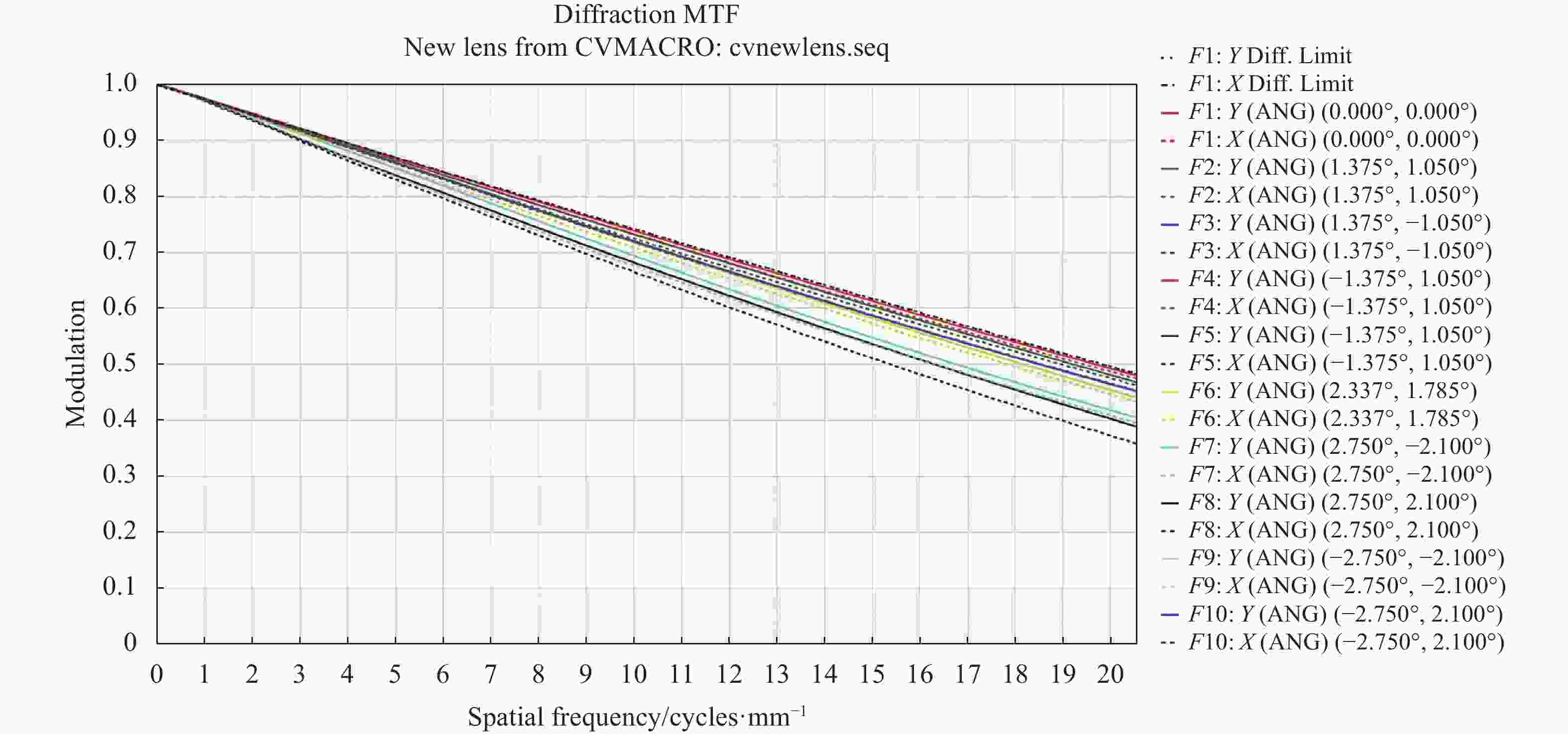
图 5 光学传递函数
Figure 5. Optical system transfer function
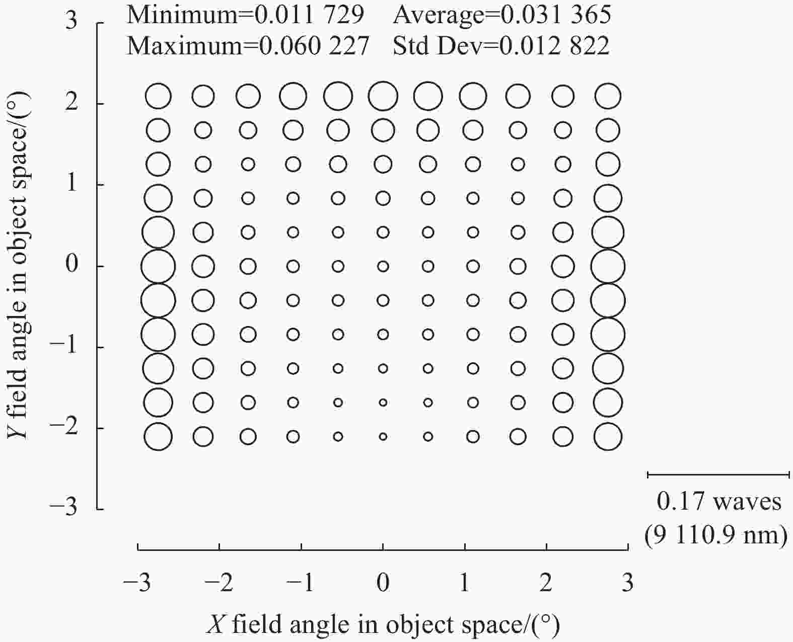
图 6 全视场波像差分布
Figure 6. Distribution of all field of view wave aberrations
-
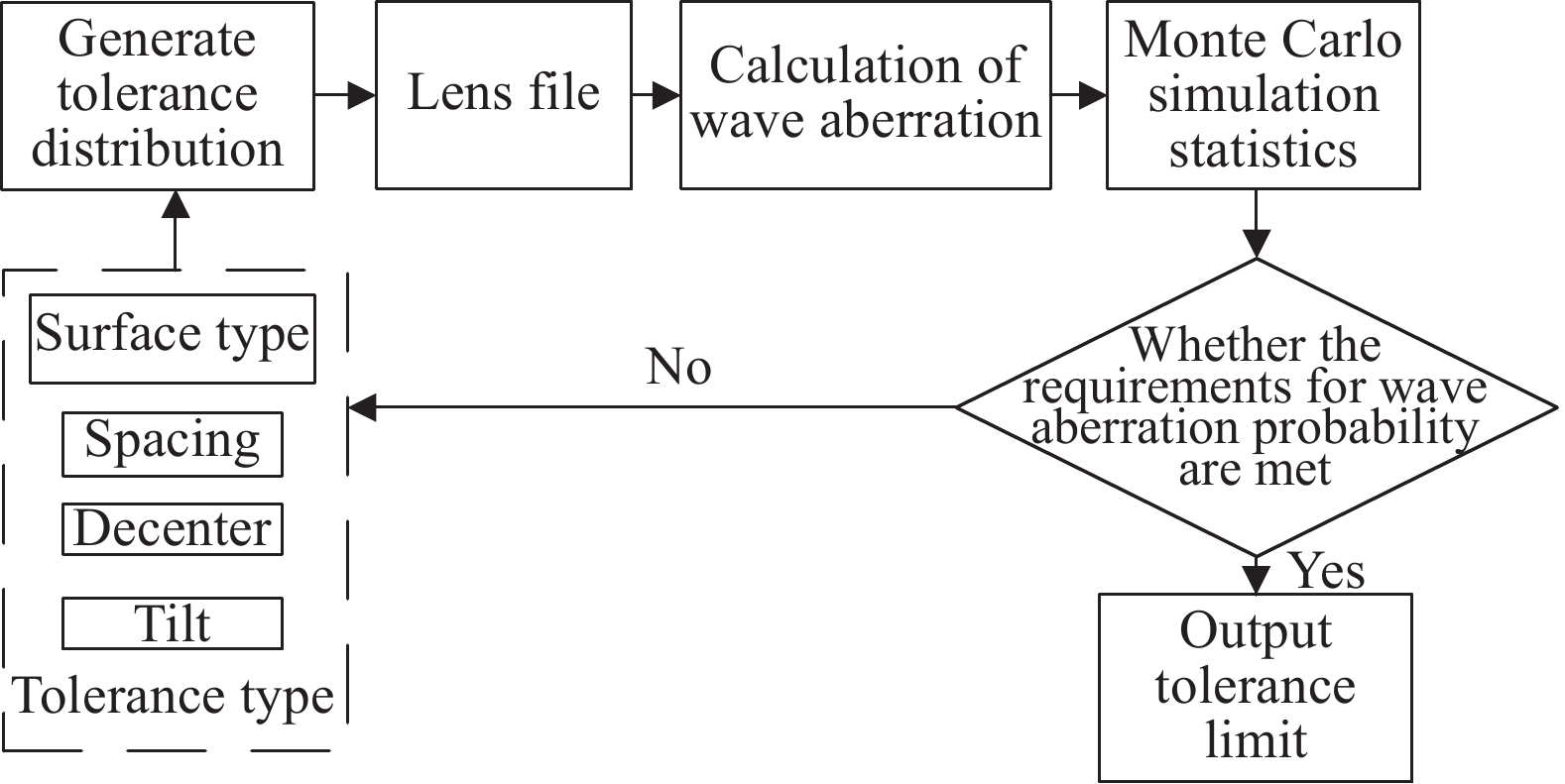
光学系统公差分析流程如图7所示。首先依据加工装调经验,生成一组公差限,进行蒙特卡洛模拟统计,如满足概率则放松公差限,如不满足概率则收紧公差限,最终给出一个合理的公差带范围。

图 7 公差分析流程
Figure 7. Tolerance analysis process
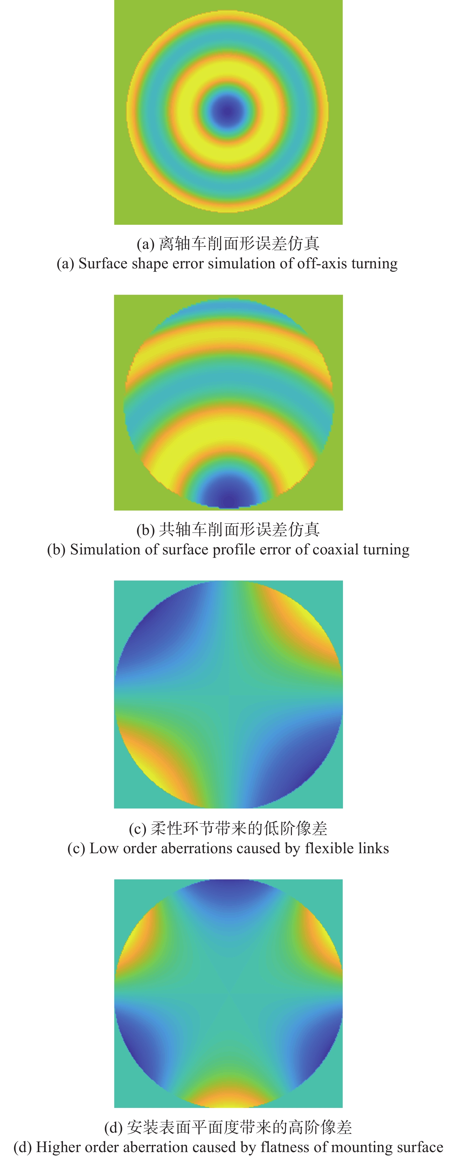
其中,面形误差的生成依据具体的加工方法进行模拟,离轴车削表面面形误差通常关于通光口径对称,如图8(a)所示,共轴车削表面面形误差通常关于母线对称,如图8(b)所示。除此之外,还要考虑具体的结构设计形式和装卡方式带来的影响,如柔性设计环节带来的低阶像差和安装表面平面度带来的高阶像差等的影响,如图8(c)、图8(d)所示。
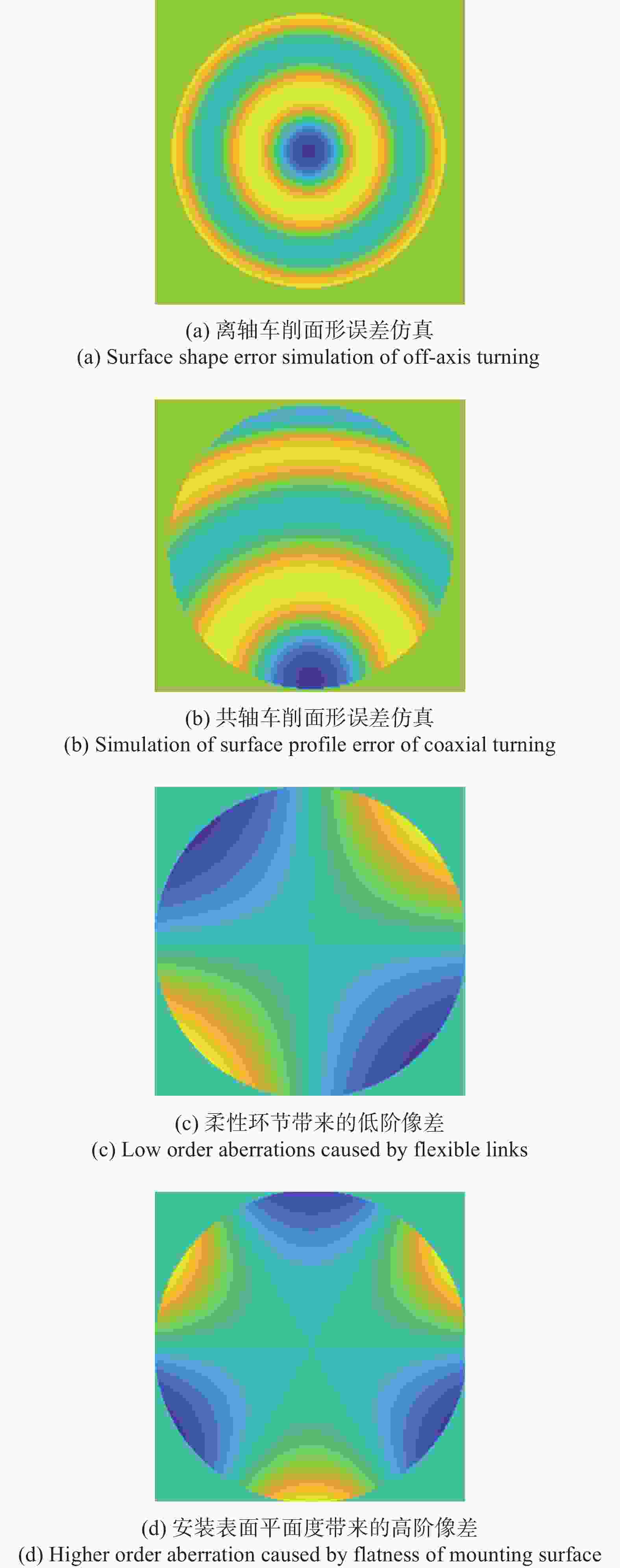
图 8 面形误差类型模拟
Figure 8. Surface error type simulation
间隔、偏心、倾斜的误差精度则来源于机械结构设计的图纸要求,公差分布选用高斯概率密度函数。采用蒙特卡洛统计1000次的公差分析结果,给出概率统计结果,最终确定的公差限如表1所示,可以满足90%概率系统RMS优于0.05λ (λ=10000 nm),上述公差限也在合理的加工和装调范围内。
表 1 各类公差限范围
Table 1. Value range of various tolerances
Tolerance type Primary mirror Secondary mirror Third mirror Surface type/μm PV 1,
RMS 0.12PV 1,
RMS 0.12PV 1,
RMS 0.12Spacing/mm ±0.01 ±0.02 NA Decenter/mm ±0.01 ±0.01 ±0.02 Tilt/(″) ±20 ±20 ±36 -
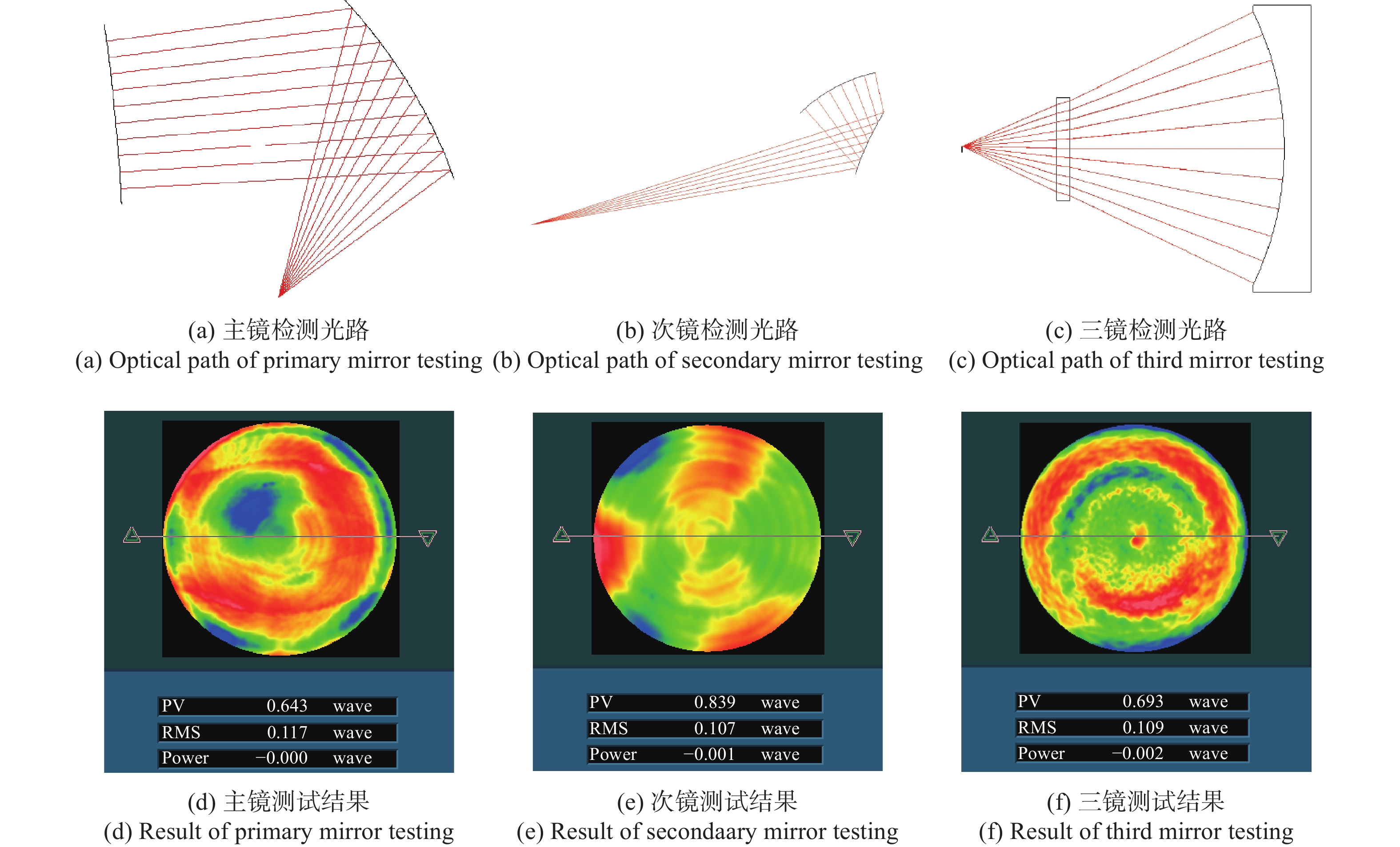
面形检测光路如图9所示,其中主镜、次镜为二次曲面面型,采用无像差点检测面形精度,检测光路如图9(a)、图9(b)所示;三镜为自由曲面,采用CGH检测,检测光路图9(c)所示。由于无像差点检测光路不是沿着法线入射出射,检测完成后需逐点修正才能重构出真实面形误差,其中主镜k值为−0.721,面形误差重构系数均值为1.1;次镜k值为−2.036,面形误差重构系数均值为1.05。
由检测结果可知,主镜和三镜主要由图9(a)、图9(c)所示因素影响,次镜由图9(d)所示因素影响,这与加工和装卡方式有关。

图 9 反射镜面形检测光路及结果
Figure 9. Optical path and results of mirror surface shape detection
-
基于制冷型探测器的离轴三反光学系统装调完毕后,在干涉仪上进行了全视场波前测试,如图10所示。测试结果如表2所示,全视场像质≤0.8λ (λ=632.8 nm),等效中心工作波长0.056λ (λ=9.11 μm),满足设计要求。
表 2 波前误差测试结果
Table 2. Results of wavefront error measurement
Field of view Wavefront error (λ=632.8 nm) (0°,0°) 0.53λ (2.75°,2.2°) 0.66λ (2.75°,−2.2°) 0.62λ (−2.75°,2.2°) 0.74λ (−2.75°,−2.2°) 0.79λ 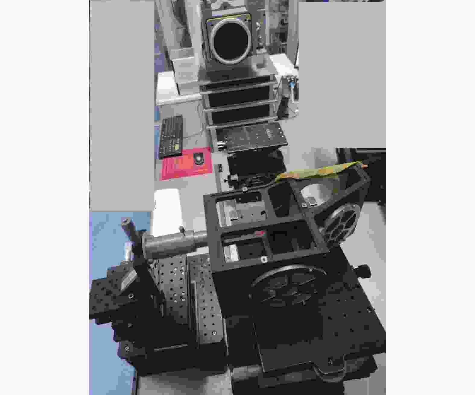
图 10 光学系统波前误差测试
Figure 10. Wavefront error measurement of optical system
-
文中采用二次成像光路形式和XY多项式自由曲面,设计了一套基于640×512@24 μm长波红外制冷型探测器、F数为2、视场角为5.5°×4.4°的离轴三反光学系统,同时也对反射式自由曲面光学系统的公差分析、面形检测过程进行了具体分析和示例,光学系统全视场波前测试结果表明,系统在中长波双波段均具有良好的像质。
自由曲面离轴三反光学系统解决了现有离轴三反光学系统子午视场小、不具备实入/出瞳、F数偏大、探测器后截距定制等技术难点,可以很好地满足未来宽波段、高灵敏度的探测需求。随着技术的不断进步,未来自由曲面反射式光学系统必将得到更为广泛的应用。
Development of off-axis three-mirror system based on free-form surface
-
摘要: 针对宽波段、大视场机载光学系统的设计需求,采用二次成像光路形式和XY多项式自由曲面,研制了一套基于640×512@24 μm长波红外制冷型探测器的离轴三反光学系统。相比传统离轴三反光学系统,该系统解决了制冷型探测器冷光阑匹配问题和子午视场较小的设计难点,具有宽波段、大视场、透过率高、体积紧凑、无中心遮拦、无热化等技术优点。光学系统焦距160 mm,工作波段8~12 μm,F数2,视场5.5°×4.4°,主镜和次镜均为二次曲面,三镜为XY多项式自由曲面。光学系统波前测试结果表明,系统波像差全视场平均值0.067λ (λ=9.11 μm),具有较好的成像质量。Abstract:
Objective With the development and wide application of large area array and high resolution cooled detectors, the requirements for imaging field of view and imaging performance of optical system are becoming higher and higher. Compared with rotationally symmetric spherical and aspheric surfaces, free-form surfaces have higher design degrees of freedom. At present, domestic and foreign scholars mostly use 2-3 free-form surfaces to realize the design of the off-axis three-mirror optical system of free-form surfaces. The optical system configuration is the primary imaging rectangular field of view optical path or the secondary imaging real entrance pupil linear field of view optical path. There are few reports on the design of the secondary imaging real entrance pupil rectangular field of view optical path. To meet the design requirements of wide-band and large-field airborne optical system, a set of off-axis three-mirror optical system for long-wave infrared cooled detector is developed using the form of secondary imaging optical path and XY polynomial free-form surface. Methods In this paper, a fast numerical iterative calculation method based on the aberration equation (Fig.1) is presented. A program is compiled using MATLAB to solve the initial structure of the central field of view based on the Tamer T. Elazary quadratic field vector aberration equation. The field of view is continuously increased for calculation, and a better initial structure is finally obtained. The node aberration optimization method is used to balance the coma and astigmatic node characteristics in the full field of view (Fig.3), and gradually reduce the number of free surfaces. The Monte Carlo algorithm is used for tolerance analysis to determine the reasonable tolerance limit distribution (Tab.1). Finally, the interferometer is used to detect the surface shape of the aspheric and free-form surface components machined by turning (Fig.9). Results and Discussions The optimized off-axis tri-reflector optical system contains only one free surface (Fig.4), and the efficiency of the cold diaphragm is 100%. Its field of view reaches 5.5°×4.4°, full field MTF is close to diffraction limit. The maximum RMS of full-field wave aberration is 0.06λ and the minimum value is 0.01λ. The average value of wave aberration is 0.03λ (λ=9.11 μm). The imaging quality of the system is good. The system solves the problem of cold aperture matching and the design difficulty of small meridian field of view for the cooled detector. The system is compact without central barrier. And it has technical advantages of wide band, large field of view, high transmittance, etc. Conclusions This paper designs an off-axis three-mirror optical system based on the 640×512@24 μm long wave infrared cooled detector. The system adopts the secondary imaging optical path and XY polynomial free surface. The focal length of the optical system is 160 mm, and the working band is 8-12 μm. The F number of this system is 2, and the field of view reaches 5.5°×4.4°. At the same time, this paper also analyzes the tolerance of the reflective free-form surface optical system. The surface shape of the parts was tested after machining. The wavefront test results of the optical system show that the full-field average value of the system wave aberration is 0.067λ (λ= 9.11 μm). The whole system has good imaging quality. -
Key words:
- optical design /
- off-axial three-mirror /
- freeform surface /
- infrared optical system
-
表 1 各类公差限范围
Table 1. Value range of various tolerances
Tolerance type Primary mirror Secondary mirror Third mirror Surface type/μm PV 1,
RMS 0.12PV 1,
RMS 0.12PV 1,
RMS 0.12Spacing/mm ±0.01 ±0.02 NA Decenter/mm ±0.01 ±0.01 ±0.02 Tilt/(″) ±20 ±20 ±36  下载: 导出CSV
表 2 波前误差测试结果
Table 2. Results of wavefront error measurement
Field of view Wavefront error (λ=632.8 nm) (0°,0°) 0.53λ (2.75°,2.2°) 0.66λ (2.75°,−2.2°) 0.62λ (−2.75°,2.2°) 0.74λ (−2.75°,−2.2°) 0.79λ
下载: 导出CSV
-
[1] Rodgers J M. Unobscured mirror designs [C]//Proceedings of SPIE, 2002, 4832: 33-60. [2] Yang T, Zhu J, Hou W, et al. Design method of freeform off-axis reflective imaging systems with a direct construction process [J]. Opt Express, 2014, 22(8): 9193-9205. [3] Xu Fenggang, Huang Wei, Xu Mingfei. Design of off-axis three-mirror optical system based on Wassermann-Wolf equations [J]. Acta Optica Sinica, 2016, 36(12): 1222002. (in Chinese) doi: 10.3788/AOS201636.1222002 [4] Yang Tong, Zhu Jun, Jin Guofan. Starting configuration design method of freeform imaging and afocal systems with a real exit pupil [J]. Applied Optics, 2016, 55(2): 345-353. doi: 10.1364/AO.55.000345 [5] Cao Chao, Liao Sheng, Liao Zhiyuan, et al. Design of cooled freeform-surface off-axis reflective optical system [J]. Acta Optica Sinica, 2019, 35(11): 1122001. (in Chinese) [6] Zhu Jun, Hou Wei, Zhang Xiaodong, et al. Design of a low F-number freeform off-axis three-mirror system with rectangular field-of-view [J]. Journal of Optics, 2015, 17(1): 015605. [7] Takayuki N, Yasuhisa T. Configuration of an off-axis three-mirror system focused on compactness and brightness [J]. Applied Optics, 2005, 44(5): 776-783. doi: 10.1364/AO.44.000776 [8] Elazhary T T. Generalized pupil aberrations of optical imaging systems [D]. Arizona: University of Arizona, 2014. [9] 潘君骅. 光学非球面的设计与检验, 苏州: 苏州大学出版社, 2004 Pan Junhua. The Design, Manufacture and Test of the Aspherical Optical Surface [M]. Suzhou: Soochow University Press, 2004. (in Chinese) [10] Chang Lingying, Zhang Qiang, Qiu Yuehong, et al. Design of telecentric relay optical system with broadband and real entrance pupil [J]. Infrared and Laser Engineering, 2021, 50(10): 20210091. (in Chinese) [11] Xu Ningyan, Chen Lu, Huang Jing, et al. Review of design methodology for starting-point of freeform surface imaging optical system [J]. Infrared and Laser Engineering, 2022, 51(2): 20210852. (in Chinese) [12] Fuerschbach K, Davis G E, Thompson K P, et al. Assembly of a freeform off-axis optical system employing three φ-polynomial Zernike mirrors [J]. Opt Lett, 2014, 39(10): 2896-2899. -

 点击查看大图

图(10) / 表(2)
计量
- 文章访问数: 133
- HTML全文浏览量: 30
- PDF下载量: 73
- 被引次数: 0


