


-
长度作为物理学的基本单位之一,其精确测量在前沿基础学科还有先进技术应用中具有极为重要的意义,正是由于绝对距离测量的普适性和重要性,一直受到国内外学者的重视,并且推动遥感[1]、雷达[2-3]、装备制造[4]等相关领域的发展,对社会发展起到了积极的作用。
传统的绝对距离测量方法一般采用光学干涉技术,但该方法存在测量距离较短、“位相模糊”、易受噪声干扰等问题[5-7]。为了使距离测量摆脱非模糊距离过短从而对积累相位测量的依赖,非光学干涉距离测量方法吸引了人们的广泛兴趣[8-10]。这种方法采用频率合成激光,将距离信息由光电探测器转换为电子学信号,再对其进行频率解调,还原得到距离信息。2017年,Yang Hongzhi建立了相位噪声对双频光测距影响模型,实验显示的拍频噪声和相位抖动与理论模型十分匹配[11];2020年,邹峰利用声光调制器搭建了双频光扫频测距平台,测距实验装置中的待测距离为24.06 m、激光频率扫描范围10 MHz,测量精度为0.04 m[12]。根据双频光噪声理论模型可知激光噪声、调制信号噪声和物体震动都会导致测距信号相位抖动,从而影响双频光测距仪的测量精度[11-13]。因此,实验中一方面需要提高双频光频率扫描范围,增加测距信号长度以减小相位抖动产生的测量误差;另一方面需要对调制信号的信号源进行时基溯源以补偿晶振受老化、温度影响产生的频率偏移,提高双频光的频率精度[14-17]。
针对上述误差因素,文中提出一种溯源北斗时间基准的非光学干涉激光扫频测距方法,通过采用光纤电光调制器制备双频激光,能够实现大范围的频率扫描,解决测距信号长度不足的关键难题;采用北斗/GPS双模时钟进行授时校准,实现对信号源时基的远程溯源,解决调制频率的溯源难题;采用电子学外差探测与自混频相结合的方案,将高频交流光电流信号解调出低频绝对距离信息,解决了噪声高、信号弱的技术难题。
文中首先推导并建立了非光学干涉双频激光扫频测距理论模型;其次设计了北斗/GPS双模时钟,搭建了双频光扫频测距光路;最后利用电子元器件进行信号解调,通过曲线拟合的方法求解出待测距离,验证了该方法的正确性,为利用频率合成激光测距提供了新的研究思路。
-
双频激光扫频测距原理见图1,采用偏振正交的非干涉激光进行测距研究,由电子学差频信号代替光学干涉信号,再对其进行频率解调还原得到距离信息。
推导在自由空间中双频光测距模型的传递函数,经过调制后双频合成光的光场表达式为:
$$ E\left( t \right) = {\alpha _{\text{S}}}{{{{\rm{e}}}}^{ - i{\omega _{\text{1}}}t + i{\theta _{\text{1}}}}} + \xi {\alpha _{\text{S}}}{{{{\rm{e}}}}^{ - i{\omega _{\text{2}}}t + i{\theta _{\text{2}}}}} $$ (1) 式中:
${\alpha _{{\rm{S}}}}$ 为非移频光的振幅;$ \xi $ 为移频光与非移频光振幅的比值;$ {\theta _1} $ 和$ {\theta _2} $ 分别为非移频光与移频光的初始位相。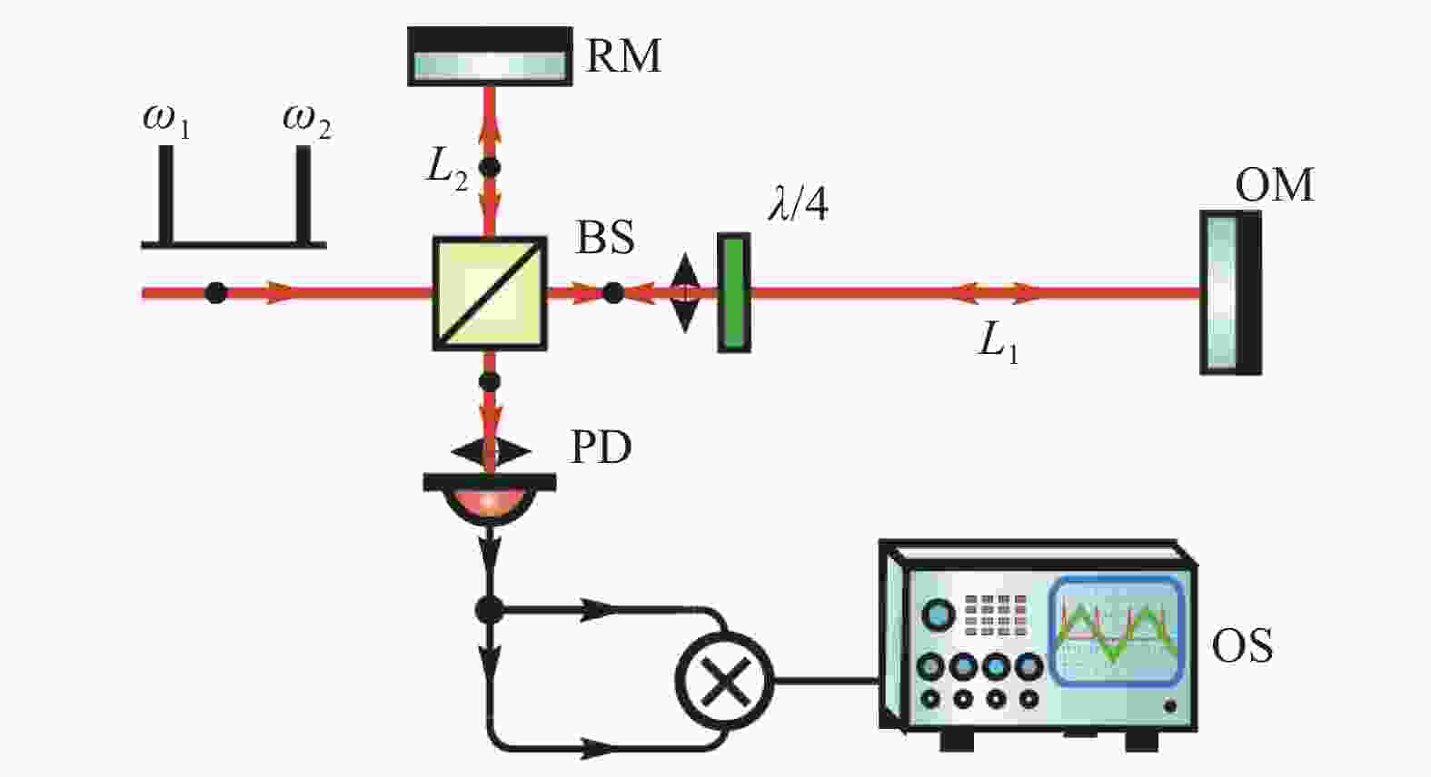
图 1 双频光测距原理
Figure 1. Principle of dual frequency laser ranging
双频合成光经过分束器后被分为测距光和参考光。若将迈克尔逊干涉仪的水平方向(
${L_1}$ )光路放置一个四分之一波片(λ/4),使其快(慢)轴与入射线偏振光成45°,当测距光两次经过四分之一波片后,偏振态将会发生改变,由S光变为P光,所以干涉仪输出的激光场是具有P和S两个偏振方向的光波。经过不同的光程后,测距光、参考光对应的P、S偏振激光可表示为:$$ E_{{m}}^{}\left( t \right) = \frac{i}{{\sqrt 2 }}{\alpha _{\text{P}}}\left( {{{\rm{e}}^{ - i{\omega _{\text{1}}}t + i{\theta _{\text{1}}}}} \cdot {{\rm{e}}^{{\text{2}}i{k_{\text{1}}}{L_1}}} + \xi {{\rm{e}}^{ - i{\omega _{\text{2}}}t + i{\theta _{\text{2}}}}} \cdot {{\rm{e}}^{{\text{2}}i{k_{\text{2}}}{L_1}}}} \right) $$ (2) $$ E_{{r}}^{}\left( t \right) = \frac{i}{{\sqrt 2 }}{\alpha _{\text{S}}}\left( {{{\rm{e}}^{ - i{\omega _{\text{1}}}t + i{\theta _{\text{1}}}}} \cdot {{\rm{e}}^{{\text{2}}i{k_{\text{1}}}{L_{\text{2}}}}} + \xi {{\rm{e}}^{ - i{\omega _{\text{2}}}t + i{\theta _{\text{2}}}}} \cdot {{\rm{e}}^{{\text{2}}i{k_{\text{2}}}{L_{\text{2}}}}}} \right) $$ (3) 式中:
${L_1}$ 和$ {L_2} $ 分别代表测距光与参考光所经过的光程;${k_{\text{1}}}$ 和${k_2}$ 分别代表非移频光与移频光的波速。光波再次经过BS合束后,干涉仪会输出具有待测距离信息的测距信号,由于参考光与测距光偏振态相互垂直,合束后并不会产生光学干涉,探测器处光强等于两正交偏振光光强叠加。设
$\tau $ 时刻双频光的频差$\varOmega \left( \tau \right) = {\omega _2} - {\omega _1}$ 、波速$k = \omega /{{c}}$ 、初始位相差$\Delta \theta {\text{ = }}{\theta _{\text{2}}}{{ - }} {\theta _{\text{1}}}$ ,可以将探测器接收到的测距光与参考光对应光强分别表示为:$$ {I_{{m}}}\left( t \right) = \frac{{\alpha _{\rm{{P}}}^2}}{4}\left\{ {{\text{1 + }}{\xi ^{\text{2}}}{\text{ + 2}}\xi \cos \left[ {\varOmega \left( \tau \right)\left( {t - 2{L_1}/{{c}}} \right) - \Delta \theta } \right]} \right\} $$ (4) $$ {I_{{r}}}\left( t \right) = \frac{{\alpha _{\rm{{S}}}^2}}{4}\left\{ {{\text{1 + }}{\xi ^{\text{2}}}{\text{ + 2}}\xi \cos \left[ {\varOmega \left( \tau \right)\left( {t - 2{L_{\text{2}}}/{{c}}} \right) - \Delta \theta } \right]} \right\} $$ (5) 通过观察公式(4)、(5)可知,探测器输出的光电流包含:(1)直流项
$ \bar J\left( {DC} \right) $ ; (2)高频项$\tilde J\left( \tau \right)$ 。在信号解调的过程中,文中使用自混频的方法进行解调的数据处理。自混频后得到的是两光电流的平方和,由于混频器能过滤掉直流部分,将针对测距光与参考光对应的交流项分析:$$ {\tilde J_m} = \frac{{{\alpha ^2}}}{2}\xi \cos \left[ {\varOmega \left( \tau \right)\left( {t - 2{L_1}/{{c}}} \right) - \Delta \theta } \right] $$ (6) $$ {\tilde J_r} = \frac{{{\alpha ^2}}}{2}\xi \cos \left[ {\varOmega \left( \tau \right)\left( {t - 2{L_{\text{2}}}/{{c}}} \right) - \Delta \theta } \right] $$ (7) 为简化计算将交流项的位相化为
${\theta _{{m}}}$ 和${\theta _{{r}}}$ ,得到混频后两光电流平方和$ {J_{{\text{out1}}}} $ 表示为:$$ \begin{split} J_{{\text{out1}}}^{} = & \frac{{\text{1}}}{{\text{2}}}{\left( {{{\tilde J}_{{r}}}{\text{ + }}{{\tilde J}_{{m}}}} \right)^{\text{2}}}= \\ & {\text{ }}\frac{{\xi {\alpha ^{\text{4}}}}}{{\text{8}}}\left( {{{\cos }^2}{\theta _{{m}}} + {{\cos }^2}{\theta _{{r}}}{\text{ + 2}}\cos {\theta _{{m}}}{\text{*}}\cos {\theta _{{r}}}} \right) =\\ & {\text{ }}\frac{{\xi {\alpha ^{\text{4}}}}}{8}\left[ \begin{gathered} {\text{1 + }}\frac{{\text{1}}}{{\text{2}}}\left( {\cos 2{\theta _{{m}}} + \cos 2{\theta _{{r}}}} \right)+ \\ \cos \left( {{\theta _{{m}}} + {\theta _{{r}}}} \right){\text{ + }}\cos \left( {{\theta _{{m}}}{{ - }}{\theta _{{r}}}} \right) \\ \end{gathered} \right] \end{split}$$ (8) 最后利用低通滤波器(Low-pass filter)消除高频项,对公式(8)中低频项进行分析:
$$ \begin{split} J\left( \tau \right) =& \frac{{\xi {\alpha ^{\text{4}}}}}{8}\cos \left( {{\theta _{{m}}}{{ - }}{\theta _{{r}}}} \right) =\\ & {\text{ }}\frac{{\xi {\alpha ^{\text{4}}}}}{8}{\text{cos}}\left[ {\varOmega \left( \tau \right)\cdot 2\Delta L/{{c}}} \right] \end{split}$$ (9) 式中:
$ \Delta L $ 为两光波的光程差,考虑空气折射率$ n $ 的影响,$ \Delta L $ 与待测距离$ l $ 的关系为$ \Delta L = nl $ 。由于双频光的频差随着时间线性变化,得到位相与待测距离$ l $ 的关系:$$ \varphi \left( \tau \right){\text{ = }}\varOmega \left( \tau \right) \cdot 2nl/{{c}} $$ (10) 设
${\tau _1}$ 时刻扫频开始,此时位相为:$$ \varphi \left( {{\tau _1}} \right){\text{ = }}\varOmega \left( {{\tau _1}} \right) \cdot 2nl/{{c}} $$ (11) 设
${\tau _2}$ 时刻扫频结束,此时位相为:$$ \varphi \left( {{\tau _2}} \right){\text{ = }}\varOmega \left( {{\tau _2}} \right) \cdot 2nl/{{c}} $$ (12) 将公式(11)和(12)做差后可得到:
$$ l = \frac{{\varphi \left( {{\tau _2}} \right) - \varphi \left( {{\tau _1}} \right)}}{{\varOmega \left( {{\tau _2}} \right) - \varOmega \left( {{\tau _1}} \right)}} \cdot \frac{{{c}}}{{{\text{2}}n}} $$ (13) 以上为红外双频光测距理论的推导,建立了非光学干涉扫频测距理论模型。
-
文中将搭建溯源北斗时基的双频光扫频测距装置,如图2所示。双频光光源①通过光纤电光调制器制备,实现频率调谐范围大、扫描速度快的功能;测距光路②为一个迈克尔逊干涉仪,加入两个四分之一波片,实现两路光的偏振正交,从而得到无光学干涉的效果;信号处理部分③采用电子学外差探测与自混频相结合的方案,将高频交流光电流信号解调出低频绝对距离信息。

图 2 双频光扫频测距装置
Figure 2. Dual-frequency laser scanned-frequency ranging device
-
双频光光源如图3所示,核心装置为电光调制器,当电光调制器接入调制信号后,出射的光波包含两种频率成分(
$ {\omega _{\text{1}}} $ ,$ {\omega _{\text{2}}} $ ),分别为非移频光(基带)和调制移频光,其中移频光的频率表达式为:$$ {\omega _{\text{2}}}{\text{ = }}{\omega _{\text{1}}}{\text{ + }}{\omega _{{\text{RF}}}} $$ (14) 式中:
$ {\omega _{\text{1}}} $ 为激光的初始频率;$ {\omega _{{\text{RF}}}} $ 为调制信号频率。当调制信号源加载随时间线性变化的频率时,双频光的频差也随之改变,实现频率扫描。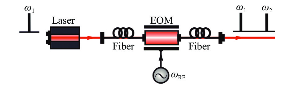
图 3 双频光光源
Figure 3. Dual-frequency laser source
文中利用电光调制器(NIR-MX-LN-10, IXBLUE)输出的光波含有未移频光(基带)的特点产生双频光,相较于声光调制器产生双频光的方法,不仅免去了移频光与未移频光合束的步骤,而且避免了声光调制器衍射光导致光路偏移的缺点。通过更快的调制速率实现大范围的频率扫描有利于后续的数据处理,利用电光调制器产生双频激光是文中的一个创新点。
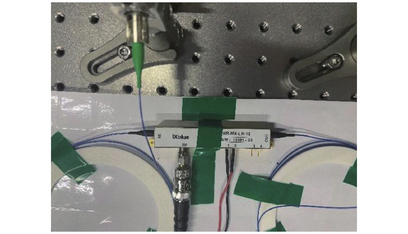
图4为电光调制器实物图,具有两个输入端口,分别为DC的直流偏置、RF的射频信号。通过调整直流偏置电压大小,能够周期性改变非移频光的光强,为了提高拍频信号的信噪比,需要使非移频光光强处于0.5π附近。电光调制器输出双频光的频差等价于信号源的调制频率,所以信号源的频率误差会影响双频光的频差,从而影响测距结果,因此还需要进行信号源校准。

图 4 电光调制器实物图
Figure 4. Physical drawing of electro-optical modulator
-
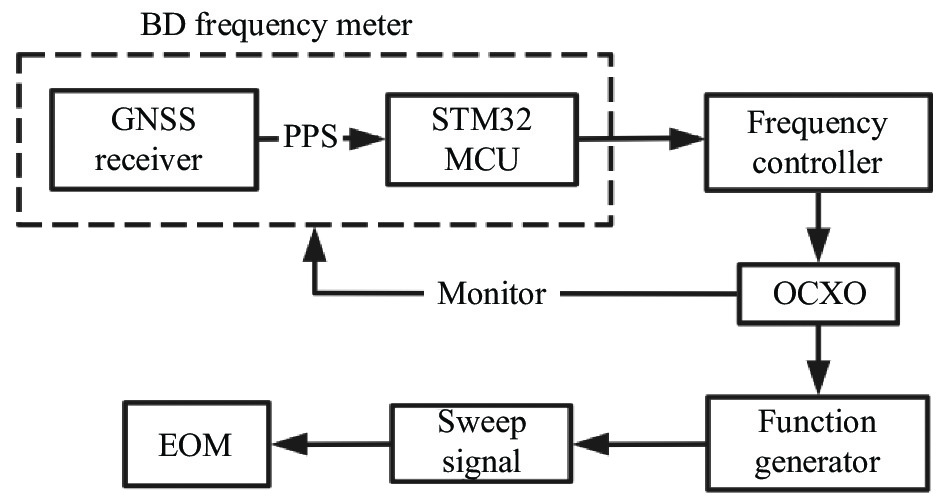
文中设计了北斗/GPS时钟对信号源进行授时校准。校准方案如图5所示,OCXO输出10 MHz时钟信号作为信号源的外部基准;由北斗/GPS频率计监测频率误差;通过PID算法对OCXO进行反馈控制,实现时基远程溯源,这是文中的另一个创新点。

图 5 信号源时基溯源示意图
Figure 5. Diagram of signal source time base traceability
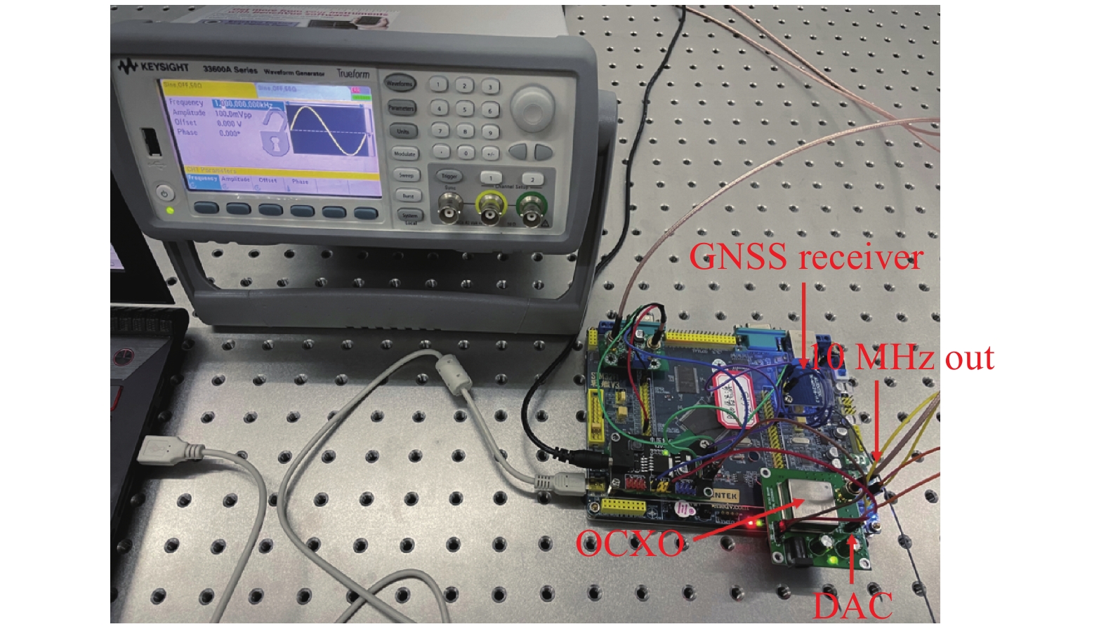
北斗/GPS时钟的核心装置为北斗/GPS频率计,设计原理为:将待测信号进行TTL电平转换后输入STM32通用定时器的外部时钟通道;将PPS脉冲连接定时器的输入捕获通道,同时边沿检测器设定为上升沿触发。定时器会对待测信号脉冲计数,将计数值储存在CNT寄存器中,当每个PPS的上升沿到来时,捕获寄存器都会读取CNT寄存器的计数值并由DMA输出。通过分析相邻PPS上升沿的计数值得到待测信号频率,并由串口协议输出至上位机,实时记录信号频率。
由于定时器处于外部时钟模式,因此单片机内部晶振误差不会对频率测量造成影响,测量误差主要由作为触发信号的PPS产生。北斗/GPS频率计使用SkyTraq公司S1216 F8-BD双模接收机,双卫星导航系统接收机能观测的卫星数量大于仅支持北斗接收机,所以在环境复杂的城市中提供了更加优越的性能,接收机输出的PPS时间精度能够达到10 ns,实物如图6所示。

图 6 GPS/BD时钟
Figure 6. GPS/BD clock
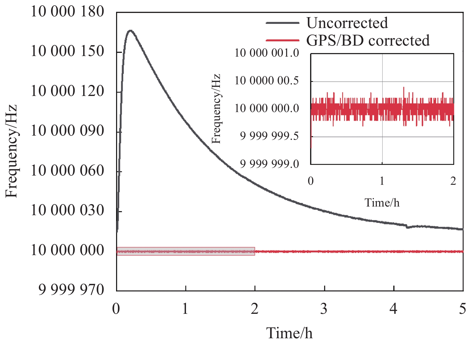
实验使用Keysight-33600函数发生器作为信号。如图7所示,通过北斗/GPS频率计对信号源输出的10 MHz基信号进行频率测量,测量记录结果显示授时校准后信号源时基频率误差能控制在 ± 0.3 Hz以内,频率精度达到0.03 ppm,避免了信号源内部时基由晶振老化、温度等原因产生的频率误差。

图 7 时基频率
Figure 7. Time base frequency
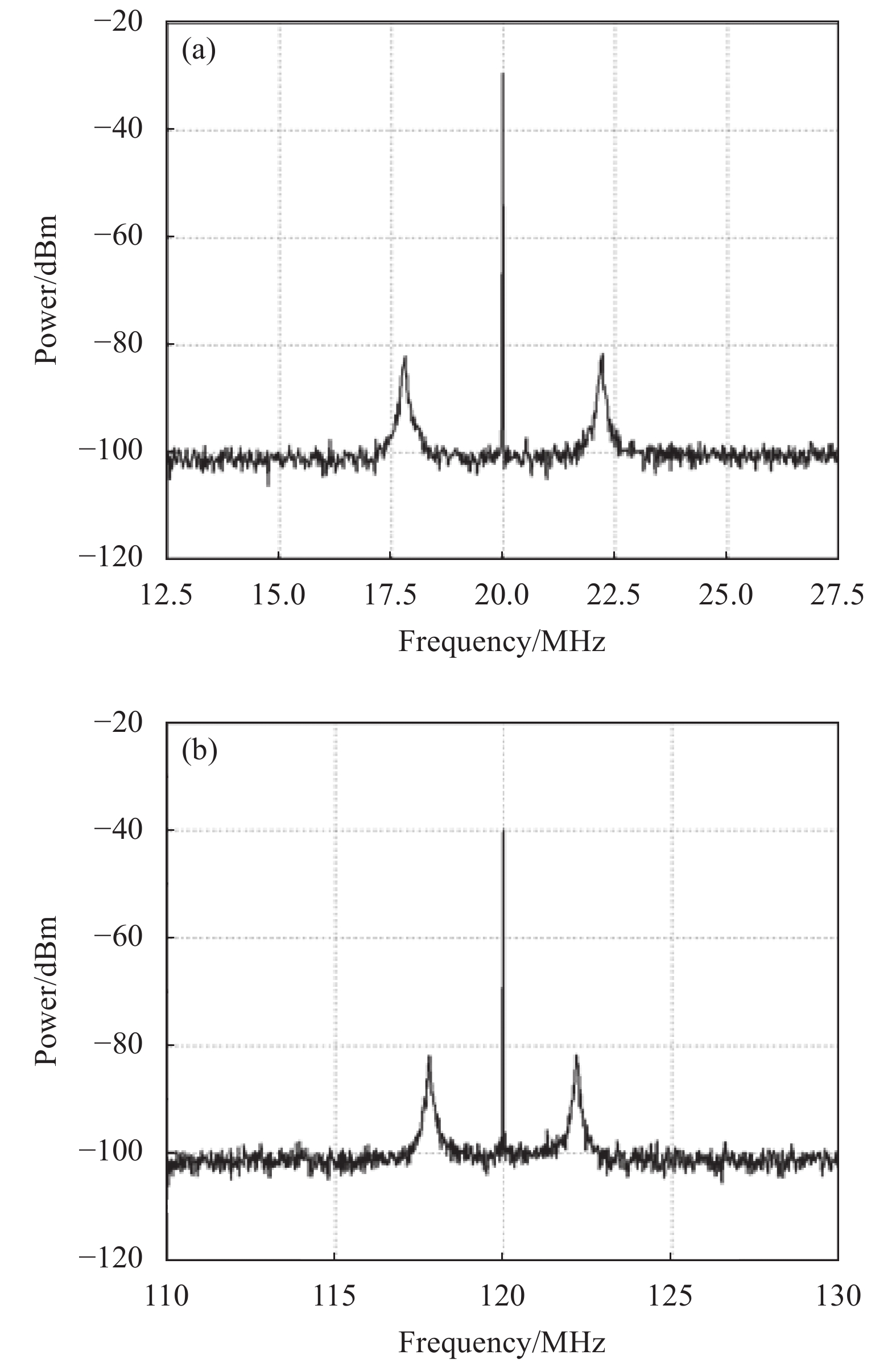
信号源时基校准后首先要对双频光的拍频信号进行探测。把电光调制器出射的双频激光,通过光电探测器进行接收,并连接频谱仪进行信号拍频测试。图8(a)为信号源加载20 MHz时的拍频结果,拍频信号频率为20 MHz;图8(b)为信号源加载120 MHz时的拍频结果,拍频信号频率为120 MHz。通过观察可以发现,当信号源加载一定的频率时,搭建的红外双频光源能够产生相应的拍频信号。

图 8 (a) 20 MHz拍频结果;(b) 120 MHz拍频结果
Figure 8. (a) 20 MHz beat frequency test results; (b) 120 MHz beat frequency test results
-
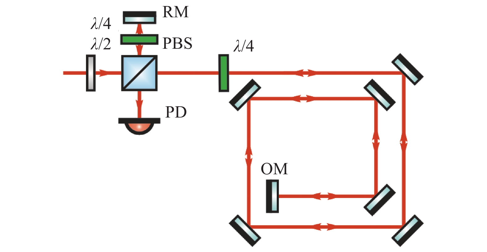
在搭建测距光路时首先利用PBS把光路分成两束,一路作为参考光;一路作为测距光。各自放置一个四分之一波片(λ/4),使这两束光反射后在探测器处不会产生光学干涉,提高了探测器处的光功率,也减小了环境扰动对于实验结果的影响,为后续的信号解调和处理提供了帮助。利用这种非光学干涉的双频光进行绝对距离测量是文中的又一个创新点。
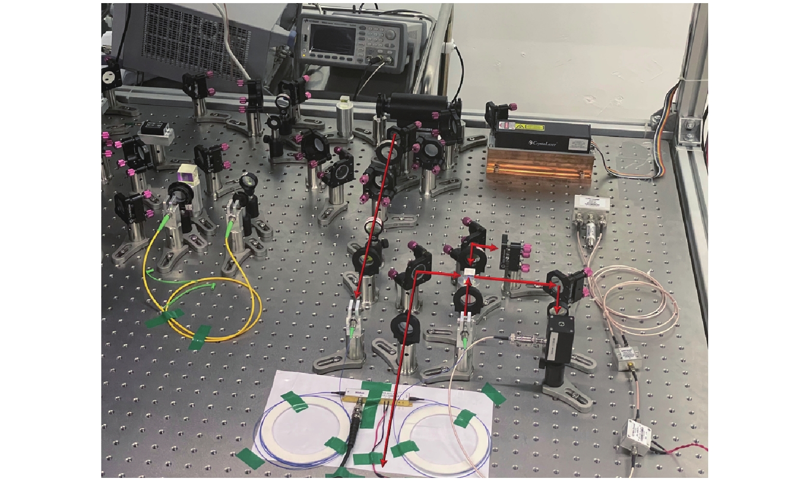
由于光学平台面积有限,为实现大范围的距离测量搭建如图9所示的环形测距光路。因为介质镜对光的损耗较低,所以环形测距光路选择介质镜作为反射镜使用。红外双频光光源(见图3)与环形测距光路(见图9)相结合就得到了测距实验光路(见图10),表1为主要部分对应光功率。

图 9 环形测距光路
Figure 9. Ring ranging optical path

图 10 测距装置实物
Figure 10. Ranging device
表 1 主要部分对应的光功率
Table 1. Optical power of the main part
Position Optical power/mW Laser output 8.18 EOM output 5.23 Measuring optical 0.174 Reference optical 0.174 -
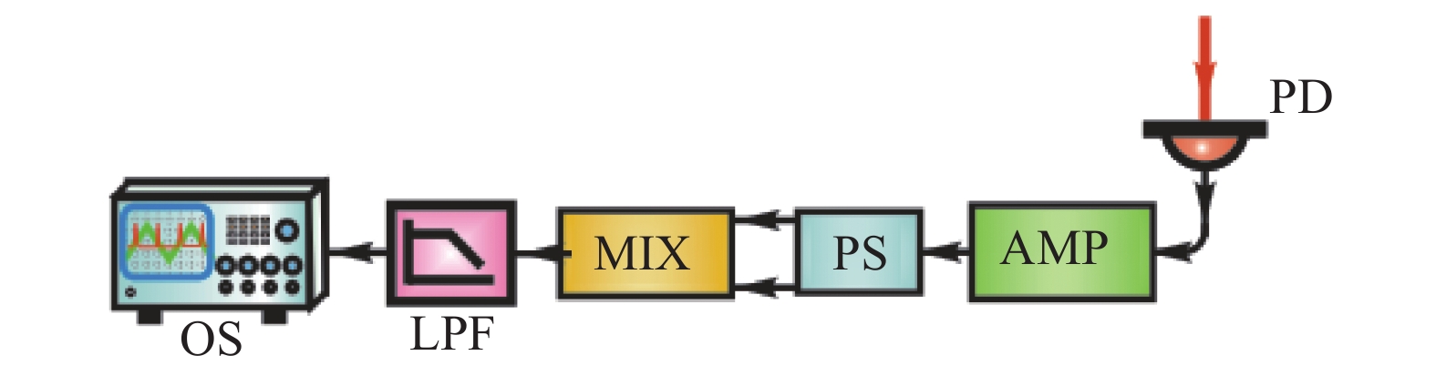
文中利用两光电流的电子学干涉代替光学干涉,降低了环境噪声的影响。基于双频光测距理论可知电子学干涉信号属于高频信号,需要对接收的光电流进行平方和处理,解调为低频信号分析。如图11所示,功率分流器(Z99 SC-62,Mini-Circuits)将信号一分为二后再进行自混频处理(ZAD-1,Mini-Circuits),得到的中频信号由低通滤波器(BLP-1.9, Mini-Circuits)去掉高频部分完成解调。

图 11 信号解调
Figure 11. Signal demodulation
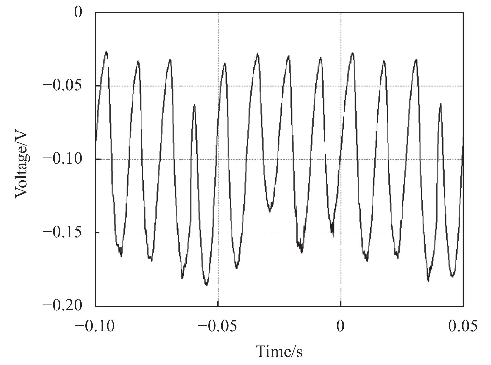
由于信号拍频测试中,信号源加载频率为20、120 MHz能够观察到明显的拍频信号,文中将信号源扫频区间取为[20, 120] MHz,经解调处理后得到了测距信号,如图12所示。

图 12 解调信号
Figure 12. Demodulated signal
-
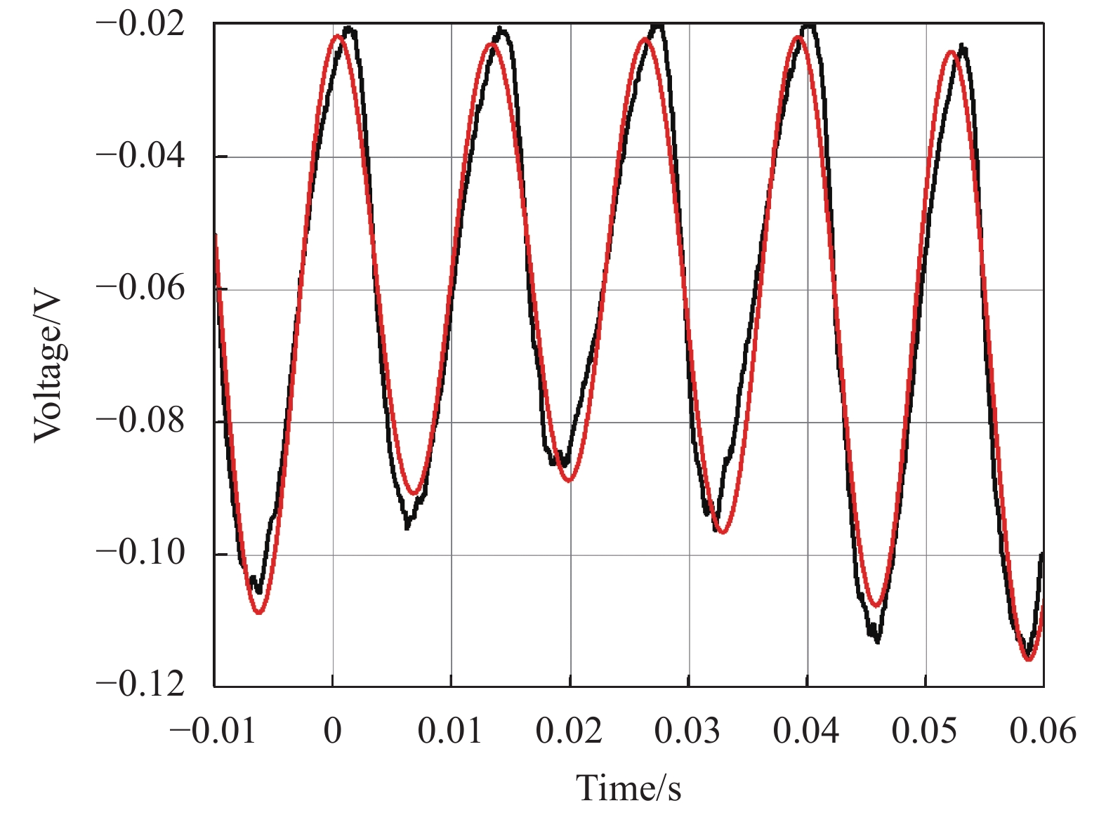
文中对采集的解调信号进行数据处理得到待测距离。首先截取一个完整扫频周期的解调信号使用Origin曲线拟合,拟合函数为:
$$ \begin{split} y = & [{B_0} + {B_1}(x - {x_0}) + {B_2}{(x - {x_0})^2} + {B_3}{(x - {x_0})^3}] + \\& [{A_0} + {A_1}(x - {x_0}) + {A_2}{(x - {x_0})^2} + {A_3}{(x - {x_0})^3}] \cdot \\& \cos [2{\text{π }}(x - {x_0})/T] \end{split} $$ (15) 式中:
$ T $ 代表正弦曲线的周期。解调信号对应$ T $ 值与扫频相位差$ \Delta \varphi \left( \tau \right) $ 的关系为:$$ \Delta \varphi \left( \tau \right){\text{ = }}1/T \cdot \Delta \tau $$ (16) 信号源扫频步长为:
$$ k = {{\Delta \varOmega \left( \tau \right)} \mathord{\left/ {\vphantom {{\Delta \Omega \left( \tau \right)} {\Delta \tau }}} \right. } {\Delta \tau }} $$ (17) 此次实验中信号源扫频时间
$ \Delta \tau $ 为100 ms,扫频范围$ \Delta \varOmega \left( \tau \right) $ 为100 MHz,得到步长$ k $ 为1 GHz。将公式(16)代入公式(13)得到:$$ l = \frac{{{c}}}{{2n}} \cdot \frac{{\varphi \left( {{\tau _2}} \right) - \varphi \left( {{\tau _1}} \right)}}{{\varOmega \left( {{\tau _2}} \right) - \varOmega \left( {{\tau _1}} \right)}} = \frac{{{c}}}{{2n}} \cdot \frac{{\Delta \tau }}{{T\Delta \varOmega \left( \tau \right)}} = \frac{{{c}}}{{2nkT}} $$ (18) 设折射率
$ n $ 为1,得到距离表达式为:$$ l = \frac{{\text{3}}}{{20T}} $$ (19) 图13为一个扫频周期解调信号的拟合结果,相关系数R=0.972,说明拟合函数收敛,拟合成功。

图 13 解调信号拟合曲线
Figure 13. Demodulated signal fitting curve
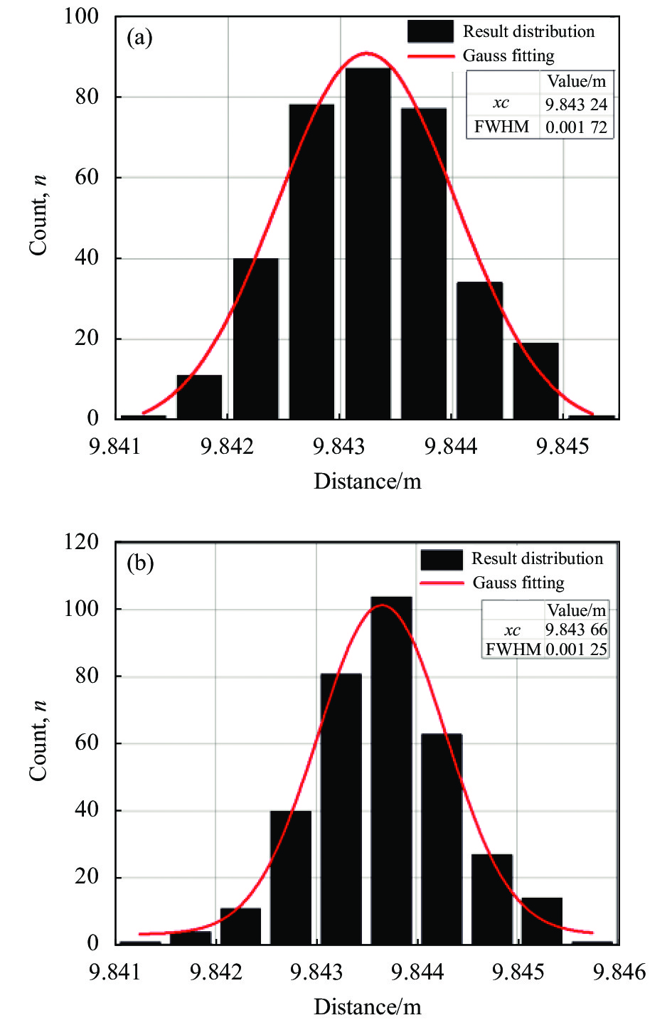
实验在GPS/北斗时钟授时校准前后对测距信号进行采样。为了减小实验的随机误差,分别截取了350组测距信号进行拟合,将
$ T $ 值代入公式(19)得到待测距离。为统计实验数据,计算了350个测量结果的高斯分布,如图14所示。测量误差由高斯分布的FWHW参数读出,表2为绝对距离测量结果。
表 2 实验结果
Table 2. Experimental results
Uncorrected Corrected Distance/m 9.8432 9.8436 Uncertainty/mm 1.72 1.25 文中通过溯源北斗时基的方法避免了信号源的内部时基随晶振老化,温度等因素产生的频率波动影响实验结果,使EOM双频光扫频测距实验精度提高28%,得到绝对距离测量结果为9.8436 m,测量误差1.25 mm,与测距理论相符,验证了该方法的正确性。
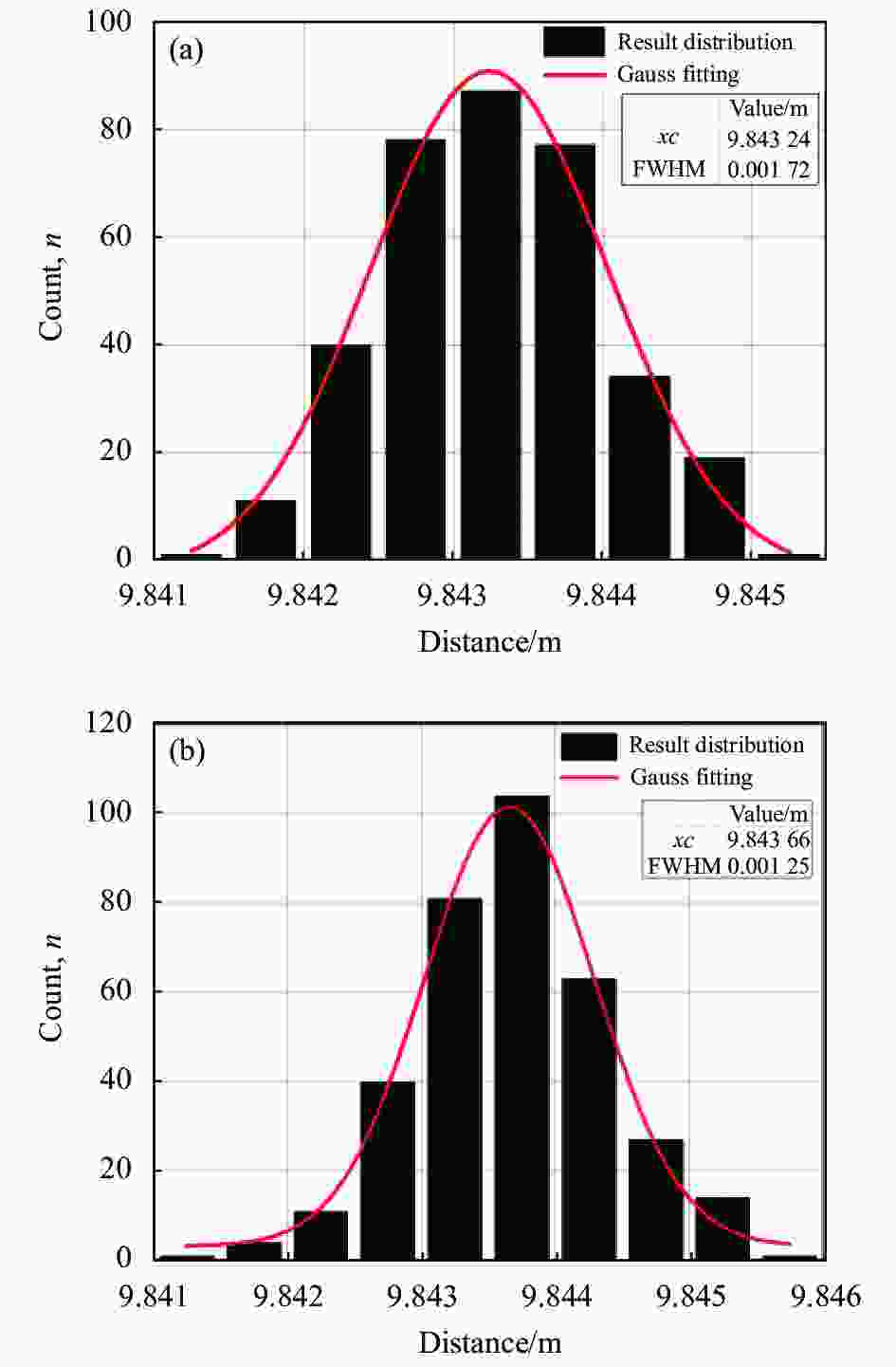
图 14 (a)溯源前实验结果高斯分布; (b)溯源后实验结果高斯分布
Figure 14. (a) Gaussian distribution of experimental results before correction; (b) Gaussian distribution of experimental results after correction
-
第1章建立了扫频测距理论证,但是推导的过程中都是基于理论条件下讨论,在实际的实验环境中出现了解调信号位相抖动导致拟合误差影响测量结果。
根据测距模型将位相与光程的关系写为:
$$ \Delta \varphi \left( \tau \right) = \frac{{4{\text{π }}}}{{{\Lambda _{{{eq}}}}\left( \tau \right)}} \cdot \left( {L \cdot \Delta n + n \cdot \Delta L} \right) $$ (20) 式中:
$ {\Lambda _{{{eq}}}}\left( \tau \right) $ 代表$ \tau $ 时刻的合成波长,双频光频差$ \varOmega \left( \tau \right) $ 与合成波长的关系为:$$ {\Lambda _{{{eq}}}}\left( \tau \right) = \frac{{2{{\pi c}}}}{{\varOmega \left( \tau \right)}} $$ (21) 可以得出解调信号位相抖动受到双频光频差
$ \Delta \left[ {\varOmega \left( {{\tau _2}} \right) - \varOmega \left( {{\tau _1}} \right)} \right] $ ,空气折射率$ \Delta n $ 和被测物体震动$ \Delta l $ 这三个因素的影响,所以实验中需要减小物体振动噪声、减小激光线宽、保证折射率的一致性和信号源时基的准确性。 -
文中开展了双频光绝对距离测量研究,建立了双频光扫频测距理论模型,提出利用EOM产生双频合成激光的方法,并通过远程溯源的方式对调制信号源进行时基校准,使双频光的时间频率精度满足实验需求。搭建了双频光扫频测距装置,设计了北斗/GPS时钟和电子学信号解调方案。通过北斗/GPS时钟授时校准的方式使信号源时基频率精度达到0.03 ppm。数据处理的过程中,通过对解调信号进行曲线拟合的方式得到待测距离,并统计了大量实验数据的高斯分布得出绝对距离测量结果为9.8436 m,测量误差为1.25 mm。该方法不仅避免了信号源的内部时基随晶振老化、温度等因素产生的频率误差影响测量结果,而且对于环境噪声与电子学噪声具有良好的抑制能力,能够实现大尺度绝对距离测量,相较于使用AOM扫频测距的方式测量精度提高了一个数量级,因此具有广泛的应用前景。
Experimental research of scanned-frequency laser ranging based on Beidou time base tracing and non-optical interference
-
摘要: 绝对距离测量在基础科学和技术研发领域的重要性日益彰显。由于传统的光学干涉绝对距离测量方法存在测量距离较短、“位相模糊”、易受噪声干扰等问题,计量学领域提出利用频率合成激光开展非光学干涉的绝对距离测量研究。尽管该方法实验装置简单、具有较强的抗噪声干扰能力、适用于大尺寸测量等优点,然而它对实验装置的工作频率带宽、精度具有较高的要求,先前的工作受限于以上条件,绝对距离测量精度为厘米量级。为进一步提高测距精度,提出一种溯源北斗时间基准的非光学干涉激光扫频测距方法。采用光纤电光调制器,代替空间声光调制器,激光频率扫描范围从10 MHz提高到100 MHz;采用北斗/GPS时钟作为信号源的外部基准,频率精度达到0.03 ppm (1 ppm=10−6);采用电子学外差探测与自混频相结合的方案,将高频交流光电流信号解调出低频绝对距离信息,降低了环境噪声和电子学噪声。实验得到绝对距离测量结果9.8436 m,测量精度1.25 mm。该方法减小了设备时基频率误差对测量结果的影响,实现大尺度测量同时测距精度比先前的工作提高了一个数量级,具有广泛的应用前景。Abstract:
Objective The emergence and development of laser ranging technology has solved the problem that traditional measurement methods cannot take into account large-scale and high-precision measurement. It has the advantages of high resolution, large measurement range, and easy integration, which promotes the development of remote sensing, radar, equipment manufacturing and other related fields. Although the existing laser ranging technology has made great progress in terms of ranging range and resolution, it is easily affected by interfering signals in space and equipment time base frequency errors during the ranging process, resulting in laser signal. The echo is easily disturbed by noise during the propagation process, which affects the measurement accuracy. Therefore, a large-scale, high-precision, and traceable ranging method is an urgent requirement in current practical engineering applications. Aiming at the problems of being susceptible to environmental noise interference and frequency traceability in laser ranging applications, this paper studies the method of dual-frequency optical scanning ranging without optical interference that traces the Beidou time base. This method has strong anti-interference ability against noise. The Beidou time base improves the accuracy and stability of laser modulation, and provides a new research idea for absolute distance measurement. Methods In this paper, a theoretical model of dual-frequency optical scanning ranging without optical interference is established, and the relationship among distance, signal phase and scanning frequency is obtained. A Beidou/GPS dual-mode clock is designed as the frequency reference of the ranging experiment device to achieve the effect of remote source tracing (Fig.6). An experimental device of distance measurement was built, and a dual-frequency laser was prepared based on a fiber electro-optic modulator, which has the advantages of large frequency tuning range and fast scanning speed (Fig.10). A demodulation scheme combining electronic heterodyne detection and self-mixing is designed, and the polarization orthogonal dual-frequency laser is used as the carrier of the Michelson interferometer to achieve the effect of non-optical interference, and the high-frequency photocurrent signal is demodulated to the low-frequency ranging signal, reducing environmental noise and electronic noise (Fig.11). Results and Discussions The Beidou/GPS clock uses the second pulse signal output by the dual satellite navigation system receiver as a reference, and uses the PID algorithm with dead zone to correct and compensate the frequency drift of the constant temperature crystal oscillator. Long-term frequency stability can be obtained without destroying the stability of the crystal oscillator. The frequency accuracy reaches 0.03 ppm (Fig.7). In the experiment, a device measuring dual-frequency optical sweeping distance was built that traces back to the Beidou time base. Using the signal analysis method of curve fitting, a large number of experimental data were calculated, and the measured distance in the ranging experimental device was 9.843 6 m. The measurement uncertainty is 1.25 mm, better than the untraceable 1.72 mm (Tab.3). Conclusions In this paper, the research on the absolute distance measurement of dual-frequency light is carried out, and the theoretical model of frequency-sweeping distance measurement by dual-frequency light is established. A method of using EOM to generate dual-frequency synthetic laser is proposed, and the time base calibration of the modulation signal source is performed through remote traceability, so that the time-frequency accuracy of dual-frequency light can meet the experimental requirements. A dual-frequency optical scanning ranging device was built, and a Beidou/GPS clock and electronic signal demodulation scheme was designed. Through Beidou/GPS clock timing calibration, the signal source time base frequency accuracy reaches 0.03 ppm (1 ppm=1×10⁻⁶). In the process of data processing, the measured distance is obtained by curve fitting the demodulated signal, and the Gaussian distribution of a large number of experimental data is counted to obtain an absolute distance measurement result of 9.843 6 m, with a measurement uncertainty of 1.25 mm (Fig.14). This method not only avoids the frequency error caused by the internal time base of the signal source due to the factors such as crystal oscillator aging and temperature which affect the measurement results, but also has a good ability to suppress environmental noise and electronic noise, and can achieve large-scale absolute distance measurement. The measurement accuracy is improved by an order of magnitude due to the use of AOM frequency sweep ranging, so it has a wide application prospect. -
图 8 (a) 20 MHz拍频结果;(b) 120 MHz拍频结果
Figure 8. (a) 20 MHz beat frequency test results; (b) 120 MHz beat frequency test results
图 14 (a)溯源前实验结果高斯分布; (b)溯源后实验结果高斯分布
Figure 14. (a) Gaussian distribution of experimental results before correction; (b) Gaussian distribution of experimental results after correction
表 1 主要部分对应的光功率
Table 1. Optical power of the main part
Position Optical power/mW Laser output 8.18 EOM output 5.23 Measuring optical 0.174 Reference optical 0.174  下载: 导出CSV
表 2 实验结果
Table 2. Experimental results
Uncorrected Corrected Distance/m 9.8432 9.8436 Uncertainty/mm 1.72 1.25
下载: 导出CSV
-
[1] Wang R, Chang K, Fu G, Wang S, et al. Space reconstruction using single-line LIDAR and GNSS/INS fused data [J]. Optics and Precision Engineering, 2020, 28(4): 851-858. (in Chinese) [2] Zhou H, Mao Q, Li Q. Influence of sampling frequency and laser pulse width on ranging accuracy of full-waveform LiDAR [J]. Infrared and Laser Engineering, 2022, 51(4): 20210363. (in Chinese) [3] Kim I, Martins R J, Jang J, et al. Nanophotonics for light detection and ranging technology [J]. Nature Nanotechnology, 2021, 16(5): 508-524. doi: 10.1038/s41565-021-00895-3 [4] Yang J, Yang C, Liu J, et al. Visual passive ranging system based on target feature size [J]. Optics and Precision Engineering, 2018, 26(1): 245-252. (in Chinese) doi: 10.3788/OPE.20182601.0245 [5] Li H, Zhou H, Li S, et al. Analysis on ranging error of terrain targets for ICESat-2 single-photon lidar [J]. Infrared and Laser Engineering, 2020, 49(11): 20200247. (in Chinese) [6] Bridges A, Yacoot A, Kissinger T, et al. Correction of periodic displacement non-linearities by two-wavelength interferometry [J]. Measurement Science and Technology, 2021, 32(12): 125202. doi: 10.1088/1361-6501/ac1dfa [7] Qu H, Zhang Q, Ruan Y. Laser radar based on scanning image tracking [J]. Chinese Optics, 2020, 13(3): 517-526. (in Chinese) [8] Wei Y, Jiang S, Sun G, et al. Design of solid-state array laser radar receiving optical system [J]. Chinese Optics, 2020, 13(3): 517-526. (in Chinese) [9] Pallikarakis C A, Huntley J M, Ruiz P D. Adaptive delay lines for absolute distance measurements in high-speed long-range frequency scanning interferometry [J]. OSA Continuum, 2021, 4(2): 428-436. doi: 10.1364/OSAC.404581 [10] Cole D B. An integrated heterodyne interferometer with on-chip detectors and modulators[D]. US: Massachusetts Institute of Technology, 2015. [11] Yang H, Zhao C, Zhang H, et al. Phase noise influence in a dual-frequency laser phase-shift range finder [J]. IEEE Photonics Journal, 2017, 10(1): 1-10. [12] Zhou F, Zhen T, Zhang G, et al. Research on linear sweep distance measurement based on AOM acousto-optic modulator [J]. Applied Laser, 2020, 40(6): 1132-1137. (in Chinese) [13] Salehi M R, Cabon B. Theoretical and experimental analysis of influence of phase-to-intensity noise conversion in interferometric systems [J]. Journal of Lightwave Technology, 2004, 22(6): 1510. doi: 10.1109/JLT.2004.829220 [14] 冯雪阳. 基于GPS秒脉冲的恒温晶振驯服和自适应保持技术研究与实现[D]. 电子科技大学, 2014. Feng X Y. Research and implementation on lock and self-adaptive hold technique of oven controlled crystal oscillator based on 1 pps derived from GPS[D]. Chengdu: University of Electronic Science and Technology of China, 2014. (in Chinese) [15] Zheng Zheng, Zhao Changming, Zhang Haiyang, et al. Phase noise reduction by using dual-frequency laser in coherent detection [J]. Optics & Laser Technology, 2016, 80: 169-175. [16] Yang P, Xie B, Ke X. Scheme of shot-noise-limited displacement and absolute distance measurement simultaneously using laser and white light interferometry [J]. Journal of Optics, 2022, 51(3): 557-564. [17] Yang P, Xie B, Feng S. Subhertz interferometry at the quantum noise limit [J]. Optics Letters, 2019, 44(9): 2366-2369. doi: 10.1364/OL.44.002366 -

 点击查看大图

计量
- 文章访问数: 200
- HTML全文浏览量: 61
- PDF下载量: 19
- 被引次数: 0


