


-
逆合成孔径激光雷达(inverse synthetic aperture ladar,ISAL)是一种主动的成像探测手段,工作原理与合成孔径微波雷达(ISAR)一致,信号工作在激光波段(μm量级),其通过主动发射大宽带激光信号获得距离高分辨信息,并且通过目标相对于辐射源的运动形成的虚拟孔径获得方位高分辨信息[1]。相比于传统光学相机,ISAL不受光照变化的不利影响,并可突破衍射极限,拥有极高的理论分辨率且不受距离的限制。由于激光的波长比微波短好几个数量级,又有更窄的波束,因此与ISAR相比,ISAL具有分辨率更高、抗干扰能力更强的优点[2]。根据相关报道,2018年,OrbitalA太空公司发射的EAGLE卫星就携带有ISAL载荷,推测其工作任务为对GEO重点目标进行高分辨率成像[3]。
近年来,LEO空间事件频发,随着星链卫星发射频繁,目前发射在轨的星链卫星已达到2700颗以上,其中多颗星链卫星于2021年接近我国空间站“天宫一号”;此外,俄罗斯也于2021年11月进行反卫星导弹试验,造成了多达1500多片的空间碎片。这些事件都极大地增加了LEO空间的威胁,也对LEO空间全天时全天域的观测手段提出了要求。此外,由于LEO空间威胁加剧[4],已经造成了一些我国空间重要资产的损失,如2021年3月“云海1号”发生解体,至今未能对其解体原因进行定论,这也需要提高对LEO空间重要目标的高分辨成像能力,用于保护我国重要空间资产,增强情报提供能力,用于对空间态势进行评估[5]。
基于以上需求,天基ISAL具备的全天时、高分辨率成像的优势在LEO空间的目标观测中具有巨大的发展潜力。在现有的研究中,已经有相关的研究对GEO空间目标的ISAL成像进行了评估和探索[6-10],也有相应的文献对高、中、低轨六种星看星应用模式下的天基SAL成像的参数进行了初步的分析[11]。但目前对于LEO空间的ISAL成像模式还缺乏详细的分析和评估。基于现有的研究基础[12-15],文中进一步对采用天基ISAL对LEO目标的掠飞和绕飞成像模式进行了可行性探究,分析了成像分辨率和成像时间、脉冲重复频率和回波信噪比等系统关键指标,分析了其适用的工作场合,为研究天基ISAL对LEO目标成像奠定了基础。
-
在进行低轨目标成像的天基 ISAL系统轨道设计时,一般要考虑如下约束:(1)天基ISAL和低轨卫星的轨道高度应设计得比较接近,以满足载荷成像距离的约束,同时使系统的发射功率在合理的范围;(2)为保证对低轨目标尽可能多的成像时机,还需要有较高的重访频率;(3)为实现快速高分辨的ISAL成像,静止轨道目标相对ISAL雷达的转动角速度不能太小。
卫星的轨道周期为:
$$ T{\text{ = 2}}\pi \sqrt {\frac{{{a^3}}}{\mu }} $$ (1) 式中:a为轨道半长轴;μ为万有引力常数与地球质量的乘积,这里采用WGS84 中的值,即μ=3 986 005×108 m3/s2。
对于圆轨道的卫星,将μ代入公式(1)中,其轨道周期可写为:
$$ T\text=0.009 \; 952 \; 01 \; (R+H{)}^{3/2} $$ (2) 式中:R为地球半径,其值取为6378.14 km;H为卫星的轨道高度,km。
根据ISAL卫星对目标卫星的成像模式不同,可以分为掠飞成像模式和绕飞成像模式。
LEO轨道目标主要分布在300~2 000 km轨道高度的范围内,因此在计算中轨道高度H按此范围取值;成像距离d取10~100 km,且假设为不利条件下成像(逆光成像),即ISAL卫星轨道高度低于目标卫星轨道。
-
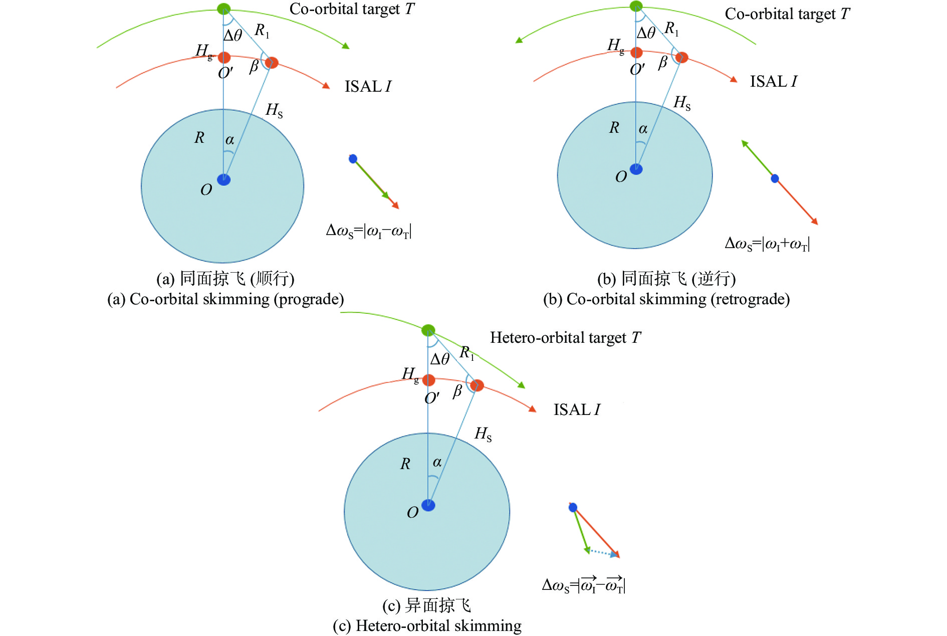
掠飞成像模式是利用ISAL载荷卫星与目标卫星自然交会的方式进行成像。这种成像方式存在同面掠飞和异面掠飞等多种情况,如图1所示。其角速度之差的一般表达式为:
图 1 掠飞成像模式示意图
Figure 1. Schematic diagram of skimming imaging mode
$$ \Delta \omega_ {\text{S = }}|\overrightarrow {\omega_ {\text{I}}} - \overrightarrow {\omega_ {\text{T}}} |{\text{ = }}\sqrt {{\text{|}}\overrightarrow {\omega_ {\text{I}}} {{\text{|}}^2}{\text{ + }} {\text{|}}\overrightarrow {\omega_ {\text{T}}} {{\text{|}}^2} - 2\cos \gamma {\text{|}}\overrightarrow {\omega_ {\text{I}}} {\text{||}}\overrightarrow {\omega_ {\text{T}}} {\text{|}}} $$ (3) 式中:
$ \overrightarrow {\omega_ {\text{I}}} $ 和$ \overrightarrow {\omega_ {\text{T}}} $ 分别为ISAL载荷卫星和目标卫星的角速度向量,其相对角速度Δω的大小取决于$ \overrightarrow {\omega_ {\text{I}}} $ 和$ \overrightarrow {\omega_ {\text{T}}} $ 的绝对值大小以及其角速度的夹角ϒ。掠飞成像重访周期为:
$$ \Delta T_{\rm{S}}{\text{ = 2}}\pi /\Delta \omega_{\text{S}} $$ (4) 在目标卫星和ISAL载荷卫星轨道高度一定的条件下,
$ \overrightarrow {\omega_ {\text{I}}} $ 和$ \overrightarrow {\omega_ {\text{T}}} $ 的绝对值大小一定。ΔωS最大的情况对应其角速度的夹角ϒ为180°的情况,即同面逆行掠飞成像的情况(图1(a)),ΔωS_max为${\text{|}}\omega_ {\text{I + }}\omega_ {\text{T}}{\text{|}}$ ;Δω最小情况对应其角速度夹角ϒ为0°的情况,即同面顺行掠飞成像,ΔωS_min为${\text{|}}\omega_ {\text{I}}-\omega_ {\text{T}}{\text{|}}$ (图1(b))。而所有的异面掠飞(图1(c)),其相对角速度ΔωS均在${\text{|}}\omega_ {\text{I + }}\omega_ {\text{T}}{\text{|}}$ ~${\text{|}}\omega_ {\text{I}}-\omega_ {\text{T}}{\text{|}}$ 范围内。掠飞模式下最大重访周期和最小重访周期随轨道高度H和成像距离d的变化如图2和图3所示。在50 km的成像距离下,300~2000 km轨道高度下的最小重访周期在0.75~1.05 h,最大重访周期在130~240 h,且均随轨道高度增加而增大。在1000 km的轨道高度,最大和最小重访周期均随成像距离减小而增加,且最大重访周期增加显著(从50 km成像距离增加至10 km,最大重访时间从170 h增加至约900 h)。
图 2 掠飞成像模式下重访周期随轨道高度的变化(d=50 km)
Figure 2. Variation of revisit period with orbit altitude in skimming imaging mode (d=50 km)
图 3 掠飞成像模式下重访周期随成像距离的变化(H=1000 km)
Figure 3. Variation of revisit period with imaging distance in skimming imaging mode (H=1000 km)
-
绕飞成像模式是指,在目标卫星围绕地球转动一周的过程中,ISAL卫星也对目标卫星环绕一周,如图4所示。其实现方式为,将ISAL卫星的轨道设计为与目标卫星同面且半长轴相同的椭圆轨道。由于半长轴相同,则ISAL卫星对目标卫星绕飞的周期
$ \Delta T_{\text{S }} $ 等于目标卫星绕地球转动的周期$ T_{\text{T }} $ ,即:$$ \Delta T_{{\rm{S}}}{\text{ = }}T_{{\rm{T}}}{\text{ = 2}}\pi /\omega _{\text{T}} $$ (5) 而ISAL卫星围绕目标卫星转动的相对角速度为:
$$\begin{split} \\ \Delta \omega_{{\rm{A}}} {\text{ = 2}}\pi {\text{/}}T_{\text{T }} \end{split}$$ (6) 需要指出的是,这里的相对角速度是以目标卫星为中心建立参考系,而在掠飞成像模式下的相对角速度是以地球为中心建立参考系。
同时,ISAL卫星绕飞过程的成像距离等于ISAL卫星与目标卫星近地点高度(或远地点高度)之差,且成像距离不影响绕飞成像的周期,这是绕飞成像模式与掠飞成像模式的差异之处。同时绕飞成像模式相比于掠飞成像模式可以实现对于目标的持续观测,获取更为丰富的目标信息。
根据绕飞的原理及公式(5),绕飞周期只与目标卫星的轨道高度有关,与成像距离无关,绕飞周期随轨道高度的变化如图5所示。在300~2000 km轨道高度范围内,绕飞周期在1.5~2.1 h,且随轨道高度增加而增大。

图 4 同面绕飞成像模式示意图
Figure 4. Schematic diagram of the co-orbital fly-around imaging mode
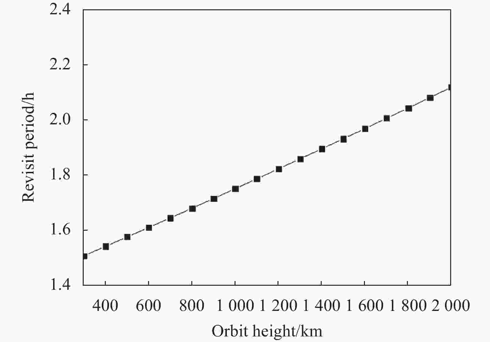
图 5 绕飞周期随轨道高度的变化
Figure 5. Variation of fly-around period with orbit altitude
-
距离向上的高分辨率成像是通过雷达测距原理实现的,其分辨率仅与发射调制信号带宽有关,可以表示为:
$$ \rho _{{r}}{\text{ = }}\frac{c}{{2B}} $$ (7) 式中:c为光速;B为激光调制带宽。
方位向的高分辨率成像是利用虚拟口径合成获得回波信号多普勒频率的高分辨成像。ISAL的方位向分辨率由波长和观测时间内目标与雷达的相对转角确定,即:
$$ \rho_{\rm{a}} {\text{ = }}\frac{\lambda }{{2\Delta \theta }} $$ (8) 从原理上可知,ISAL的成像分辨率不受收发望远镜口径的影响,仅与发射信号带宽和合成孔径长度有关,可以通过增加发射信号带宽和合成孔径长度(即合成孔径对应时间)实现等效虚拟大口径的成像效果。
在计算分析时,考虑激光调制带宽约束,成像分辨率取0.5 cm (需要B达到30 GHz)。为了达到更优的成像分辨率,选择1.55 μm波长的激光。
对于掠飞成像模式,参考目前的研究[6],选择常见的三轴稳定卫星作为目标卫星进行分析,其几何关系如图1所示。
在图1中,假设天基ISAL 设计的轨道为低于目标卫星轨道高度的圆轨道,因此,满足以下关系式:
$$ \left\{ \begin{gathered} \frac{{R_1}}{{\sin \alpha }}{\text{ = }}\frac{{H_{\rm{g}}{{ + R}}}}{{\sin \beta }}{\text{ = }}\frac{{H_{\rm{S}}{{+} R}}}{{\sin \Delta \theta }} \\ \alpha {\text{ + }}\beta {\text{ + }}\Delta \theta {\text{ = }}\pi \\ \end{gathered} \right. $$ (9) 式中:R1为天基ISAL至目标卫星T的距离,也即成像的瞬时距离,其余各变量的定义同前。
将公式(8)和(9)联立可以解得:
$$ \left\{ \begin{gathered} \beta {{ = }}\pi - \arcsin \left[ {\frac{{(H_{{\rm{g}}}{{ + }}R){\rm{sin}}\lambda /2\rho _a}}{{H_{\rm{s}}{{ + }}R}}} \right] \\ \alpha = \pi - \beta - \Delta \theta \\ R_1 = \frac{{{\rm{sin}}\alpha }}{{{\rm{sin}}\Delta \theta }}(H _{\rm{S}}{\text{ + }}R) \\ \end{gathered} \right. $$ (10) 求出角度α后便可求得ISAL成像需要的脉冲积累时间:
$$ T_\text{sa} \left\{ \begin{array}{l} \dfrac{\alpha }{\left|\omega_ \text{S}-\omega_ \text{g}\right|}\text{,}同面顺行时\\ \dfrac{\alpha }{\left|\omega_ \text{S + }\omega_ \text{g}\right|}\text{,}同面逆行时 \end{array} \right. $$ (11) 对于绕飞成像模式来说,见图4,天基ISAL对目标绕飞周期与目标卫星绕地球的周期一致,因此,其平均绕飞角速度为目标卫星的角速度,将该平均速度近似作为天基ISAL相对目标卫星的瞬时相对角速度,则绕飞过程中ISAL成像需的脉冲积累时间为:
$$ T _{\text{sa }}=\frac{{\Delta \theta }}{{\omega _{\text{g}}}} $$ (12) 图6给出了掠飞成像时脉冲积累时间的最大值与最小值随轨道高度和成像距离的变化。最小脉冲积累时间变化范围为0.1~1.2 ms,随成像距离增加而显著增大,随轨道高度增加变化有限。最大脉冲积累时间变化范围为90~125 ms,基本不受成像距离的影响,随轨道高度增加而增大。

图 6 掠飞成像模式下脉冲积累时间随轨道高度及成像距离的变化
Figure 6. Variation of coherent accumulation time with orbit altitude and imaging distance in skimming imaging mode
根据公式(5)和(12),绕飞成像的脉冲积累时间不受成像距离的影响,因此图7给出了绕飞成像时脉冲积累时间随轨道高度的变化。在300~2 000 km轨道高度,脉冲积累时间随轨道高度增加而增加,变化范围在130~190 ms。

图 7 绕飞成像模式下脉冲积累时间随轨道高度的变化
Figure 7. Variation of coherent accumulation time with orbit altitude in fly-around imaging mode
-
重复频率PRF是逆合成孔径激光雷达的重要指标之一。在ISAL应用过程中,需要调制PRF来保证转动多普勒无模糊,以保证成像效果[11]。
整个合成孔径期间内,多普勒带宽为:
$$ \Delta f_{\text{d = }}\frac{{2\Delta \omega L_{{\rm T}}}}{\lambda } $$ (13) LT为目标星的长度,为避免方位向模糊,脉冲重复频率PRF应大于fd:
$$ PRF \geqslant \Delta f_{\text{d }} $$ (14) 图8给出了不同成像模式下不同轨道高度、成像距离和目标尺寸下的最小无模糊PRF的变化情况。从图中可以看出,在不同的给定参数条件下,同面绕飞成像模式所需的最小无模糊PRF均介于同面掠飞成像模式的逆行和顺行方式之间。但在实际应用中,为了保证所有掠飞成像场景下的成像效果,其最小无模糊PRF应取同面逆行条件下的值,因此绕飞模式相比于掠飞模式,在相同的成像条件下最小无模糊PRF更小,对于激光器的要求更低,更易于应用。

图 8 最小无模糊PRF与成像距离的关系
Figure 8. Relationship between minimum PRF for unambiguous azimuth imaging and imaging distance
-
对于天基ISAL来说,回波信噪比也是一个非常重要的指标,过低的信噪比对信号传输、数据处理和系统功率都提出了巨大的挑战,根据现有文献[6],简化后的信噪比可以表示为:
$$ {\rm SNR}{\text{ = }}\frac{{P_{\text{av}}\pi \sigma \eta _{\text{d}}T_{\text{opt}}L}}{{16hvV\rho _{\text{a}}}}{\left( {\frac{L}{d}} \right)^3} $$ (15) 式中:h为普朗克常数;v为光频;V为载荷平台相对目标的运动速度。此外,取ISAL的发射平均功率Pav=500 W,目标散射截面σ=1 m2,孔径长度L分别取0.1 m、0.2 m和0.4 m,方位分辨率ρa=0.005 m,外差探测器量子效率ηd=0.8,光学系统透过率Topt=0.5,激光波长λ=1.55 μm。
根据计算得到的不同成像模式下的SNR如图9所示。从图中可以看出:
(1)轨道高度一定的情况下,随着成像距离的增加,同时天基ISAL与目标卫星间的相对速度增加,会带来信噪比降低;
(2)不同参数下,绕飞模式下的信噪比均优于掠飞模式(无论顺行或逆行);
(3)通过增加合成孔径的方式,可以有效提高信噪比;
(4)轨道高度对于信噪比的影响有限。
在远距离成像时,可以考虑通过降低成像分辨率或增大合成孔径的方式来提高信噪比。

图 9 不同成像模式下信噪比与成像距离的关系
Figure 9. Relationship between SNR and imaging distance in different imaging modes
-
为了更加直观地比较不同成像模式下的性能指标,表1给出了1000 km轨道高度,50 km成像距离,0.005 m的成像分辨率,10 m的目标尺寸和0.2 m合成孔径条件下掠飞成像和绕飞成像的性能参数。
在给定的参数下,对于所有的掠飞场景,其性能指标均在同面逆行和顺行这两种场景的范围内。从表中可以看出,相对角速度越小的掠飞场景,其所需的最小无模糊脉冲重复率PRF越小,且信噪比越高(有利于信号处理,得到清晰的图像结果),但是成像所需的脉冲积累时间增加(对激光器的相干性稳定保持的时间提出考验),特别是重访周期会大大增加。而绕飞成像相比于掠飞成像:
(1)可以实现对目标多角度的持续观测,获取更为丰富的目标信息;
(2)绕飞周期较短,可以较快地完成对目标的完整绕飞观测成像;
(3)脉冲积累时间虽然更长,但也只有155.60 ms,对于应用于ISAL的激光器来说,目前可以实现0.1~1 s稳定的相干性保持,因此绕飞成像对于工程应用完全可行;
(4)最小无模糊PRF只有掠飞成像模式的约一半(按同面逆行场景考虑);
(5)脉冲积累时间长回波信噪比高于所有掠飞成像场景,通过后期处理可以获得更为清晰的图像结果。
但是,掠飞成像在相近的轨道高度下,所有轨道面内的卫星均存在交会成像的机会,因此可以对相近轨道高度下的LEO目标进行遍历,适用于对相近轨道高度面的LEO目标进行遍历和成像,从而建立目标的特征库。
表 1 给定条件下不同成像模式的性能参数对比
Table 1. Comparison of performance parameters of different imaging modes under given conditions
Skimming imaging Fly-around imaging Co-orbital/prograde Co-orbital/retrograde Relative
anglar velocity/rad·s−11.021×10−5 2.003×10⁻³ 9.962×10⁻⁴ Revisit/fly-around
period/h170.89 0.87 1.75 Coherent accumu-
lation time/ms103.60 0.53 155.60 PRF/kHz 0.26 25.84 12.85 SNR/dB 48.30 25.37 49.61 -
文中对采用天基ISAL对LEO目标的掠飞和绕飞成像模式进行了可行性探究,选用符合工程实际应用约束的假设条件,分析了成像分辨率和成像时间、脉冲重复频率和回波信噪比等系统关键指标,并进行了对比。得到的主要结论如下:
(1)对于掠飞成像模式,在给定参数下所有的交会场景中,其各项性能指标均在同面顺行和逆行两种场景的范围内。相对角速度越小的掠飞场景,其所需的最小无模糊脉冲重复率PRF越小,且信噪比越高,但是成像所需的脉冲积累时间增加,重访周期会大大增加。
(2)绕飞成像相比于掠飞成像模式可以实现对于目标的持续观测,且绕飞周期较短,可以快速获取更为丰富的目标信息;脉冲积累时间虽然更长,但在300~2000 km轨道高度范围只有130~190 ms,对于工程应用完全可行;最小无模糊PRF减少一半,且回波信噪比更高。
(3)在对LEO目标的观测仿真计算范围内,掠飞成像模式与绕飞成像模式的各项指标均具有工程应用可行性,其中绕飞成像模式适用于对重要目标和高价值资产进行快速、高分辨率、全方位的持续观测。掠飞模式适用于对相近轨道高度面的LEO目标进行遍历和成像,从而建立目标的特征库。
Design of LEO target imaging mode with space-based Inverse Synthetic Aperture LADAR
-
摘要: 对采用天基逆合成孔径雷达(ISAL)对300~2000 km轨道高度的低轨(LEO)目标的掠飞和绕飞成像模式进行了性能分析及可行性探究,分析了成像分辨率和成像时间、最小无模糊脉冲重复频率(PRF)和回波信噪比(SNR)等系统关键指标,并进行了对比。研究结果表明:绕飞成像模式相比于掠飞成像模式可以实现对于目标的多角度持续观测,且绕飞周期较短(1.5~2.1 h),可以快速获取更为丰富的目标信息,具备进一步三维ISAL成像的潜力;脉冲积累时间虽然更长,但在300~2000 km轨道高度范围只有130~190 ms (掠飞成像为0.1~130 ms);最小无模糊PRF (对于10 m转动直径的目标,约为15 Hz)减少一半(减少了对激光器高重频的要求);由于更长的脉冲积累时间,绕飞模式的回波信噪比更高,通过后期处理可以获得更为清晰的图像结果;适用于对重要目标和高价值资产进行快速、高分辨率、全方位的持续观测。而掠飞模式适用于对相近轨道高度面的LEO目标进行遍历和成像,从而建立目标的特征库。Abstract:
Objective Inverse Synthetic Aperture LADAR (ISAL) is an active imaging detection method. Its working principle is consistent with that of Inverse Synthetic Aperture Radar (ISAR). The signal works in the laser band (μm level), which obtains range high-resolution information by actively transmitting large broadband laser signals, and obtains azimuth high-resolution information through the virtual aperture formed by the movement of the target relative to the emitter. Relevant studies have evaluated and explored the ISAL imaging of GEO space targets, and there are also corresponding researches that have preliminarily analyzed the parameters of space-based SAL imaging. However, there is still a lack of detailed analysis and evaluation of ISAL imaging mode in LEO space. In this study, the performance analysis and feasibility of using space-based ISAL for skimming and flying-around imaging modes of LEO targets is explored to provide a basis for the study of space-based ISAL imaging of LEO targets. Methods Two kinds of observation modes, skimming and flying-around imaging modes, are set up. The skimming imaging mode is to use the natural rendezvous of ISAL payload satellite and target satellite for imaging. This imaging mode has many situations, such as co-orbital skimming and hetero-orbital skimming (Fig.1). Flying-around imaging mode means that during the target satellite rotating around the earth for one circle, ISAL satellite also orbits the target satellite for one circle (Fig.4). The key system indicators such as imaging resolution, coherent accumulation time (Fig.6-7), minimum pulse repetition frequency for unambiguous azimuth imaging (Fig.8) and SNR (Fig.9) for the two kinds of observation modes are compared Results and Discussions For the skimming imaging mode, all performance indicators of all rendezvous scenes under given parameters are within the range of both forward and reverse scenes on the same plane. The smaller the relative angular velocity is, the smaller minimum pulse repetition frequency for unambiguous azimuth imaging (PRF) and the higher the signal-to-noise ratio (SNR) are required, but coherent accumulation time required for imaging is increased, especially the revisit period will be greatly increased. Compared with the skimming imaging mode, the flying-around imaging mode can realize the continuous observation of the target, and the flying-around period is short, and can quickly obtain more abundant target information; Although the coherent accumulation time is longer, it is only 130-190 ms in the range of 300-2 000 km orbit height, which is completely feasible for engineering applications; The minimum unambiguous PRF is reduced by half and the SNR is higher. Conclusions The feasibility of using space-based ISAL to scan and fly around LEO targets is explored, and the key indicators of the system, such as imaging resolution, coherent accumulation time, minimum pulse repetition frequency for unambiguous azimuth imaging are analyzed and compared with the assumptions that meet the constraints of engineering application. Within the range of observation and simulation calculation of LEO targets, all indicators of the grazing imaging mode and the flying-around imaging mode are feasible for engineering application, and the flying-around imaging mode is applicable in rapid, high-resolution and all-directional continuous observation of important targets and high-value assets. The skimming mode is suitable for traversing and imaging the LEO target at the altitude of close orbit, so as to establish the feature library of the target. -
Key words:
- imaging mode /
- space-based /
- Inverse Synthetic Aperture LADAR /
- LEO targets
-
图 2 掠飞成像模式下重访周期随轨道高度的变化(d=50 km)
Figure 2. Variation of revisit period with orbit altitude in skimming imaging mode (d=50 km)
图 3 掠飞成像模式下重访周期随成像距离的变化(H=1000 km)
Figure 3. Variation of revisit period with imaging distance in skimming imaging mode (H=1000 km)
图 6 掠飞成像模式下脉冲积累时间随轨道高度及成像距离的变化
Figure 6. Variation of coherent accumulation time with orbit altitude and imaging distance in skimming imaging mode
图 7 绕飞成像模式下脉冲积累时间随轨道高度的变化
Figure 7. Variation of coherent accumulation time with orbit altitude in fly-around imaging mode
图 8 最小无模糊PRF与成像距离的关系
Figure 8. Relationship between minimum PRF for unambiguous azimuth imaging and imaging distance
图 9 不同成像模式下信噪比与成像距离的关系
Figure 9. Relationship between SNR and imaging distance in different imaging modes
表 1 给定条件下不同成像模式的性能参数对比
Table 1. Comparison of performance parameters of different imaging modes under given conditions
Skimming imaging Fly-around imaging Co-orbital/prograde Co-orbital/retrograde Relative
anglar velocity/rad·s−11.021×10−5 2.003×10⁻³ 9.962×10⁻⁴ Revisit/fly-around
period/h170.89 0.87 1.75 Coherent accumu-
lation time/ms103.60 0.53 155.60 PRF/kHz 0.26 25.84 12.85 SNR/dB 48.30 25.37 49.61  下载: 导出CSV
-
[1] Xu C, Jin K, Jiang C, et al. Amplitude compensation using homodyne detection for inverse synthetic aperture LADAR [J]. Applied Optics, 2021, 60(34): 10594-10599. doi: 10.1364/AO.440764 [2] Zhang B, Guo J, Li Z, et al. A review for retrieving wind fields by spaceborne synthetic aperture Radar [J]. Journal of Sensors, 2022, 2022: 7773659. doi: https://doi.org/10.1155/2022/7773659 [3] Hu Haiying, Zhu Yongsheng, Jiang Xinhua. The development trend of high earth orbit space security and key technologies [J]. Aerospace Control and Application, 2022, 48(3): 1-10. (in Chinese) doi: 10.3969/j.issn.1674-1579.2022.03.001 [4] Pan Qikun, Miao Fangchen, Si Lihong, et al. Compact pulsed CO2 laser with wavelength automatic tuning [J]. Chinese Optics, 2022, 15(5): 1007-1012. (in Chinese) doi: 10.37188/CO.2022-0107 [5] Pan Guotao, Yan Yufeng, Yu Xin, et al. Design of optical system for quality evaluation of a large rectangular aperture laser beam [J]. Chinese Optics, 2022, 15(2): 307-318. (in Chinese) doi: 10.37188/CO.2021-0130 [6] Ruan Hang, Wu Yanhong, Zhang Shuxian. Geostationary orbital object imaging based on spaceborne inverse synthetic aperture ladar [J]. Infrared and Laser Engineering, 2013, 42(6): 1611-1616. (in Chinese) doi: 10.3969/j.issn.1007-2276.2013.06.041 [7] Zhang Yinbo, Li Haoyang, Sun Jianfeng, et al. Imaging algorithm of dual-parameter estimation through smoke using Gm-APD lidar [J]. Optics and Precision Engineering, 2022, 30(19): 2370-2378. (in Chinese) doi: 10.37188/OPE.20223019.2370 [8] Zhao Chuan, Guo Haitao, Wang Youyang, et al. Building outer boundary extraction from ALS point clouds using neighbor point direction distribution [J]. Optics and Precision Engineering, 2021, 29(2): 374-387. (in Chinese) doi: 10.37188/OPE.20212902.0374 [9] Ruan Hang, Zhang Qiang, Yang Yu'ang, et al. Spaceborne inverse synthetic aperture lidar imaging of nonuniformly rotating orbit object [J]. Infrared and Laser Engineering, 2023, 52(2): 20220406. (in Chinese) doi: 10.3788/IRLA20220406 [10] Wang D, Wu J, Wu T, et al. Theoretical model on geosyn-chronous orbit object imaging with space-borne synthetic aperture ladar [J]. Acta Optica Sinica, 2020, 40(18): 1828002. (in Chinese) doi: 10.3788/AOS202040.1828002 [11] Yin Hongfei, Guo Liang, Jing Dan, et al. Parameters analysis of spaceborne synthetic aperture lidar imaging [J]. Infrared and Laser Engineering, 2021, 50(2): 20200144. (in Chinese) doi: 10.3788/IRLA20200144 [12] Jin Chenfei, Tian Xiaorui, Tang Meng, et al. Research advances on non-line-of-sight three-dimensional imaging lidar [J]. Infrared and Laser Engineering, 2022, 51(3): 20210471. (in Chinese) doi: 10.3788/IRLA20210471 [13] Tian He, Mao Hongxia, Liu Zheng, et al. Airborne ladar sparse imaging on targets with micro-motions based on inverse synthetic aperture technique [J]. Infrared and Laser Engineering, 2020, 49(S2): 20200190. (in Chinese) doi: 10.3788/IRLA20200190 [14] 李建. 逆合成孔径激光雷达成像运动补偿算法研究[D]. 中国科学院大学(中国科学院光电技术研究所), 2021. Li Jian. Research on inverse synthetic aperture lidar imaging motion compensation algorithm[D]. Chengdu: University of Chinese Academy of Sciences (Institute of Optoelectronic Technology, Chinese Academy of Sciences), 2021. (in Chinese) [15] Li Jian, Wang Kunpeng, Jin Kai, et al. Inverse synthetic aperture lidar motion compensation imaging algorithm for maneuvering targets [J]. Acta Optica Sinica, 2021, 41(19): 1928001. (in Chinese) doi: 10.3788/AOS202141.1928001 -

 点击查看大图
计量
- 文章访问数: 282
- HTML全文浏览量: 57
- PDF下载量: 40
- 被引次数: 0


