


-
光模块功能是实现光电信号的相互转化与传输,主要应用于数据中心互联场景、电信市场、无源波分系统等。目前国内应用的光模块封装类型以100 Gb_s的四通道小型可插拔光模块(Quad Small Form-factor Pluggable Plus 28, QSFP-28)及200 Gb_s的四通道小型可插拔双密度光模块(Quad Small Form Factor Pluggable-Double Density, QSFP-DD)为主。随着光通信行业的发展,400 Gb_s的QSFP-DD光模块逐渐开始应用于云计算和5G网络[1]。通信速率的提升不可避免地带来了大功耗。为了保证数据中心和基站稳定地运行,必须要保证散热环境。前有Microsoft公司将数据中心建在海底,后有Facebook公司将数据中心建在北极圈,由此足以见得环境对光模块的散热是非常重要的。为了保证高速通信光模块在这种极端环境下依然可以稳定工作,需要在模块出厂测试中加入极端温度循环实验,保证光模块在极端温度下可以正常工作。目前对模块控温的有热流仪、冷热冲击试验箱和半导体制冷器(Thermoelectric Cooler, TEC)等。
热流仪的控温效率高,但其体积大、成本高、噪音大,且由于测试夹具的限制,热流仪只能进行单个模块的测试,不能并行测试多个模块;冷热冲击试验箱控温稳定,但其体积大、效率低,尤其是降温时间过长。且由于冷热冲击试验箱的结构,导致其无法在控温的同时进行其他的光模块功能测试。为了利于光模块的功能集成化测试,需要控温系统的机箱尺寸小于
$ 200 \;{\rm{mm}} \times 500 \;{\rm{mm}} \times 500 \;{\rm{mm}} $ ,且要满足噪声低于65 dB。综上所述,热流仪与冷热冲击试验箱均不适用;TEC具有质量轻、结构紧凑、占用空间小、零噪声等优点[2-5],符合光模块集成测试的需求,因此选用TEC作为热控系统的控温元件。同时,根据已有的相关理论研究[6]:液冷散热方式具有超静音、散热快等优点[7],热管散热方式虽然体积轻、占地小,但是具有自然失效的可能性[8];蒸发冷却散热方式通常应用于冶金、化工建材等行业,电子行业应用较少[9];结合热端散热优化设计[10]的实验结论,最终选用液冷的方式来提升TEC的控温效率。文中将液冷与TEC结合,设计了高速通信光模块热控系统。系统中的热电制冷器组件根据不同封装类型的待测试模块可以更换不同的测试夹具,可以实现单独测试一枚QSFP-DD光模块或并行测试两枚QSFP28光模块。而系统中的热排散系统相对于水冷机而言具有体积小、噪音低的优势,对后期光模块功能的集成化测试有着推进作用。
-
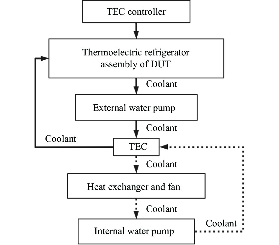
图1为高速通信光模块热控系统原理图。 它主要由待测件(Device under test, DUT)热电制冷器组件、DUT夹具、TEC控制器及TEC热排散系统组成。TEC热排散系统由外循环水路和内循环水路构成。其中,外循环水路包括冷板、水泵、TEC冷源;内循环水路包括冷板、风排、风扇及水泵。
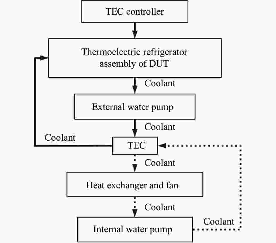
图 1 热控系统原理图
Figure 1. Schematic diagram of TEC temperature control system
-
该系统的基本工作原理为:热电制冷器组件中的TEC制冷面通过热沉与待测模块直接接触实现热量交换,从而实现对待测光模块进行控温的目的。其散热面与水冷头表面接触,并通过已冷却的水冷液进行热量交换,实现降温的目的;水冷液因吸热而温度升高后,又经热排散系统的外循环水路流入外循环水泵,继而泵入TEC冷源进行降温,最后经水路重新流回热电制冷组件中的冷板内,继续实现热量交换。热排散系统中的TEC冷源则采取液冷的散热方式散热。其主要目的是为了降低冷源中TEC的双面温差,从而提高热排散系统的制冷能力和效率。
-
高速通信光模块热控系统功能如图2所示,相关指标列于表1。在以下设计要求的基础上,要求高速通信光模块的热控系统尺寸小于
$ 200 \;{\rm{mm}} \times 500 \;{\rm{mm}} \times 500 \;{\rm{mm}} $ ,噪声低于65 dB。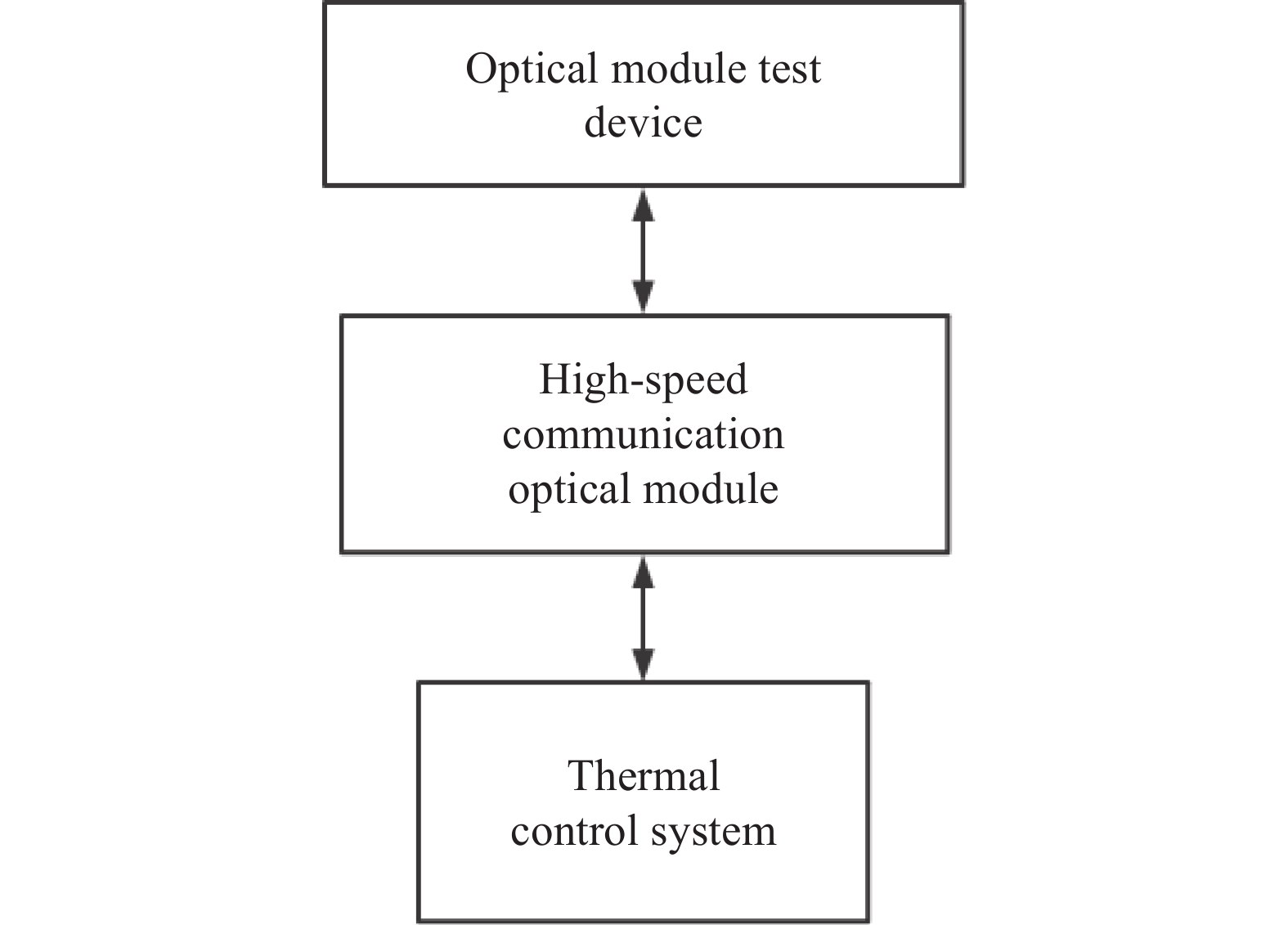
图 2 TEC热排散系统功能
Figure 2. Function of TEC cooling system
表 1 TEC热排散系统设计指标
Table 1. Design indicators of TEC cooling system
Temperature settings for TEC/℃ Shell temperature of the module/℃ Time/s −20-75 0-65 120 75-−20 65-0 120 -
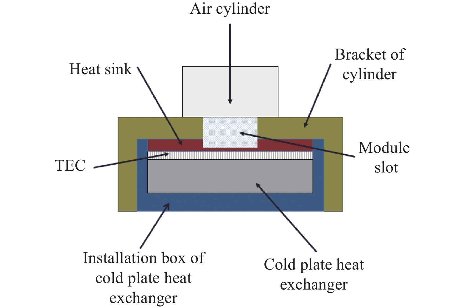
目前常用的光模块封装类型有QSFP-DD、QSFP-28和SFP28三种。有三种DUT测试板,此处以QSFP-DD光模块的热电制冷组件为例,其DUT热电制冷组件如图3所示,其三维模型如图4所示。热沉保证了光模块与热电制冷器之间进行均匀热量交换,可以有效减小总传热阻[11]。由于结构的限制导致热电制冷组件的连接点较多,从而会导致漏热;使用气缸支架及冷板散热器安装盒可以有效减少漏热现象[12]。为了降低热电制冷器双面温差以提高热电制冷器的制冷效率,采用液冷散热的方案。热电制冷器的热端直接与冷板散热器表面接触,并通过流动的低温水冷液把热量带入TEC热排散系统中,将升温的水冷液降温后重新回到冷板散热器中进行与光模块进行热量交换。需要注意的是TEC需要使用导热硅脂紧密黏贴在热沉与冷板换热器之间,这样可以使TEC与它们充分接触,利于热传导[13]。

图 3 DUT热电制冷组件
Figure 3. Thermoelectric refrigeration components at DUT

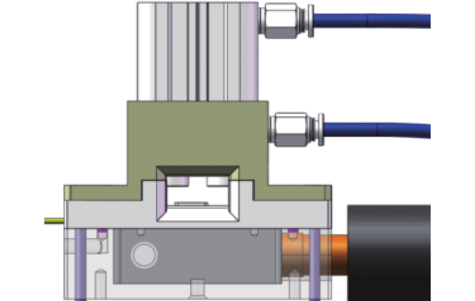
图 4 DUT热电制冷组件封装三维模型
Figure 4. Package 3D model of DUT thermoelectric refrigeration components
-
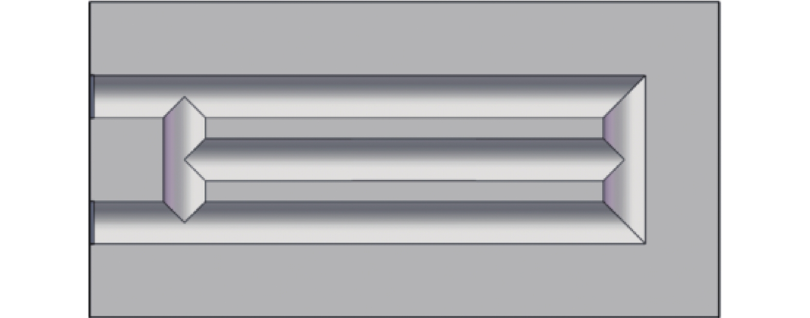
冷板换热器要保证在规定的工作环境中可以提供足够的冷量,使组件中热电制冷器热端产生的热量可以及时散掉。针对上述条件,选用的冷板换热器的平面视图如图5所示。

图 5 冷板换热器平面视图
Figure 5. Flat model of cold plate heat exchanger
-
冷板的换热能力要保证在环境为常温25 ℃时,可以满足275 W的散热需求。虽然理论上通道截面为方形的水路,其接触面积比通道截面为圆形的水路大,但考虑到成本问题,所以最终选择通道截面为圆形的冷板,其结构的截面图如图5所示,进水口与出水口之间加工成“S”型。冷板换热器的相关尺寸如表2所示。
表 2 冷板换热器相关尺寸
Table 2. Relevant dimensions of cold plate heat exchanger
Name Size/mm Name Size/mm Total height 17 Total length 50 Diameter of inlet 6 Diameter of outlet 6 Total width 50 Diameter of pipe 6 Spacing of pipes 3.5 Width of the left and right boundaries 7.75 Width of the front and back boundaries 6 Width of the upper and lower boundaries 5.5 冷板材质为紫铜T2,冷却水用接头材料为黄铜,其表面整体镀镍,起到提高强度及防氧化的作用,且表面精磨处理,用以提高表面平整度。水冷液通过水冷头时要吸收TEC热端热量,因此冷板要选择体积比热容高的材料,以保证其导热效率够快,可以及时将吸收热端热量传递给水冷液[13]。
选定的水冷液在30 ℃条件下近似于水的物性参数。已知水在30 ℃时物性参数如表3所示。
表 3 30 ℃水的物性参数
Table 3. Physical parameters of water at 30 ℃
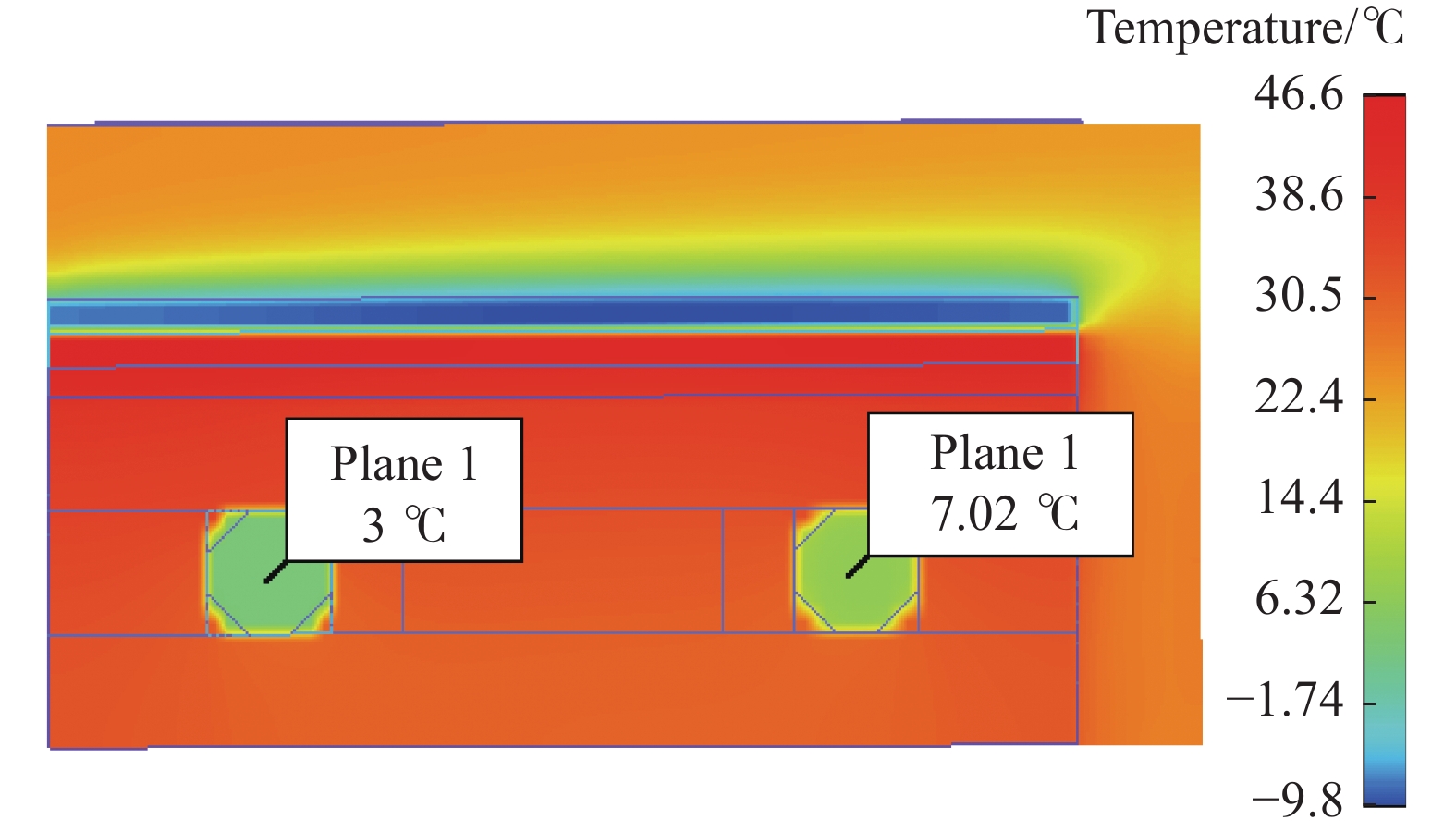
Parameter Value Thermal conductivity ${\lambda _f}/{\rm{W} }\cdot ({\rm{m} } \cdot {\rm{K} })^{-1}$ $ 0.62 $ Kinematic viscosity of fluid ${\upsilon _f}/{ {\rm{m} }^2} \cdot{\rm{s} ^{-1} }$ $ 0.805 \times {10^{{{ - }}6}} $ Fluid density $\;{\rho _f}/{\rm{kg} } \cdot { {\rm{m} }^{-3} }$ $ 995.4 $ Specific heat ${C_p}/{\rm{J} }\cdot({\rm{kg} } \cdot {\rm{K} })^{-1}$ $ 4.17 \times {10^3} $ Prandtl number Pr $ 5.42 $ 图6为采用Flotherm软件建立的热电制冷组件热仿真模型,并采用参考文献[14-15]中的计算方法对其进行封装。其进出口水冷液温度仿真结果如图6所示。由图可知,冷板换热器的进出口水冷液温差小于5 ℃。图7为热电制冷组件的制冷效果仿真图,由图可知模块壳温可以稳定在−0.382 ℃,故冷板换热器满足需求。
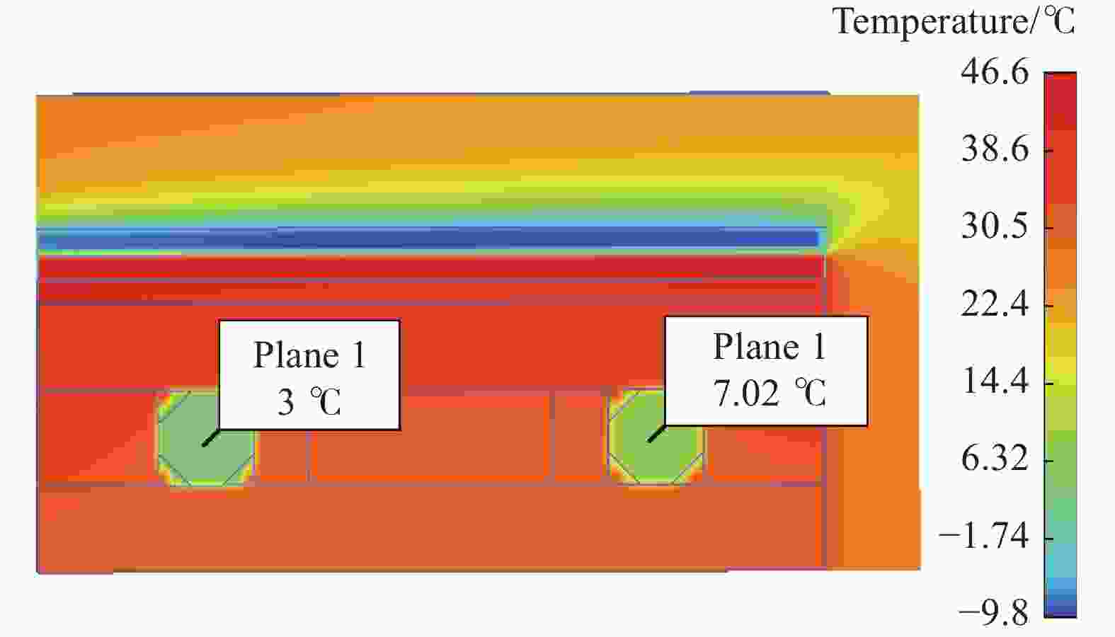
图 6 冷板换热器进出口水冷液温度
Figure 6. Cold plate heat exchanger inlet and outlet water cooling temperature
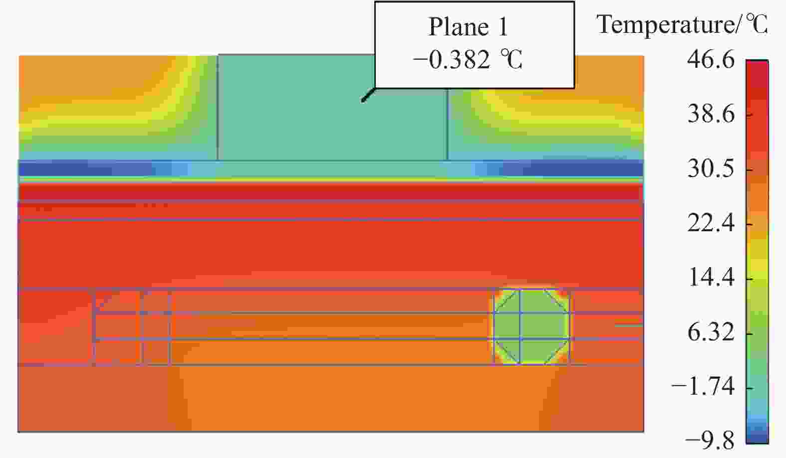
图 7 热电制冷组件的制冷效果
Figure 7. Cooling effect of thermoelectric refrigeration components
-
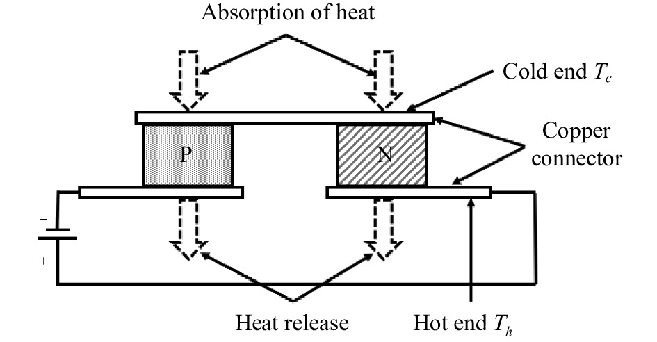
用一个直流电源直接给TEC供电,通过改变加载电流方向来控制TEC制冷或制热,其原理如图8所示。

图 8 热电制冷原理图
Figure 8. Schematic diagram of TEC
TEC的冷端制冷量为Qc,W。其大小为:
$$ {Q_c} = 2N\left\{ {\alpha I{T_c} - \left[ {\left( {{I^2}\rho } \right)/\left( {2G} \right)} \right] - k\Delta TG} \right\} $$ (1) 式中:N为热偶对数量;
$ \alpha $ 为塞贝克系数,V/℃;I为TEC电流,A;Tc为TEC制冷端温度,℃;$\; \rho $ 为TEC电阻率,$\Omega \cdot {\rm{cm}}$ ;G为TEC几何系数,含义是TEC的截面积与高度之比,cm;k为热偶对的热导率,${\rm{W}} \cdot {\rm{c}}{{\rm{m}}^{ - 1}} \cdot {{\rm{K}}^{ - 1}}$ ;$ \Delta T $ 为TEC冷热端温差,℃[16]。 -
根据相关设计经验,综合考虑换热能力、所需制冷量、升降温效率需求。文中选用的TEC基本参数如表4所示。
表 4 TEC的基本参数
Table 4. Basic parameter of TEC
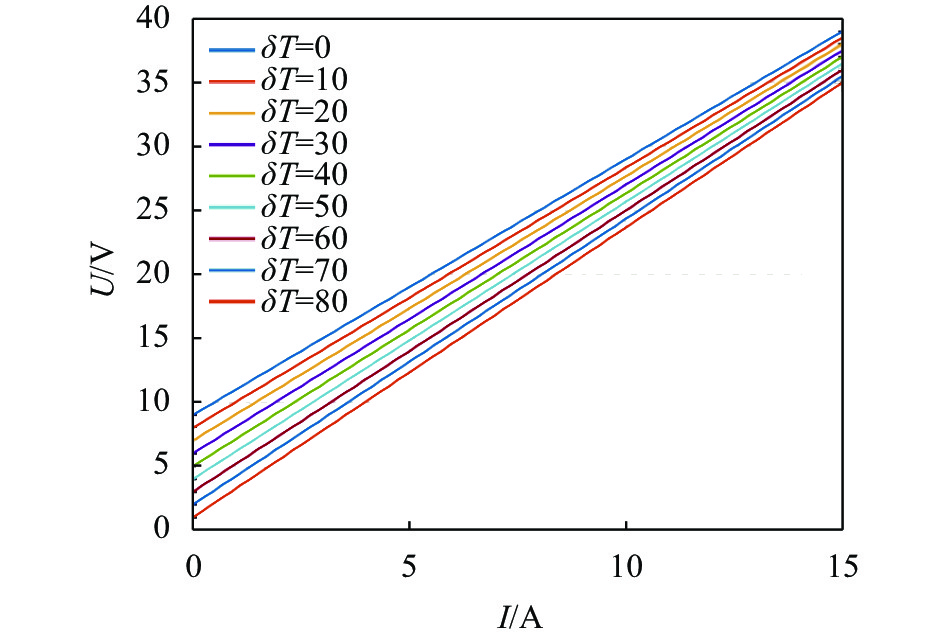
Name Numerical value Conditions for testing ${I_{\max } }/{\rm{A}}$ 15 $ {Q}_{c}=0,\delta T=\delta {T}_{\mathrm{max}},{T}_{h}=50 $ ℃ ${U_{\max } }/{\rm{V}}$ 37.4 $ {Q}_{c}=0,I={I}_{\mathrm{max}},{T}_{h}=50 $ ℃ $ \delta {T}_{\mathrm{max}}/ $℃ 78 $ {Q}_{c}=0,I={I}_{\mathrm{max}},{T}_{h}=50 $ ℃ ${Q_{c\max } }/{\rm{W}}$ 294 $ {Q}_{c}=0,\delta T=0,{T}_{h}=50 $ ℃ $ {T}_{h\mathrm{max}}/ $℃ 200 Instant 表4中:I为电流,A;U为电压,V;
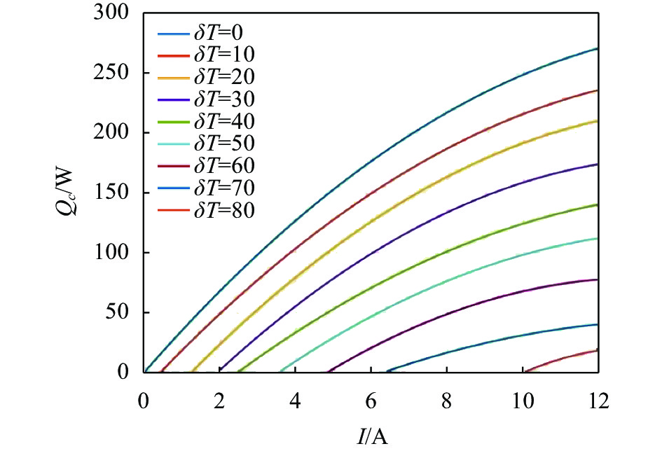
$ \delta T $ 为TEC的双面温差,℃;Qc为热电冷却器能转移的热量,W;Th为热电冷却器热端温度, ℃;下标max表示最大。对于TEC而言,当双面温差不同时,由于电气性能变化[17],上文提及到关键参数也将有所不同。图9为根据TEC厂家给出的TEC热端温度在50 ℃时的电流与电压关系数据拟合出的关系曲线。经初步测量验证,在实际使用过程中,热电制冷组件中的TEC的双面温差为50 ℃,其输入端电压为19.2 V。因此,可使用图8来推断流入此TEC的输入电流区间为[8 A,9 A]。再根据TEC的制冷量与电流的关系曲线(图10)可得,到当输入电流在8~9 A、双面温差在50 ℃的情况下,TEC的制冷量约为70~80 W。常用的高速通信光模块功率较大的封装模式是QSFP-DD封装模式,此种模式的功耗约为12 W。因此,所用TEC的制冷量完全满足应用条件。

图 9 TEC的电压-电流关系曲线
Figure 9. Voltage-current relationship curve of TEC
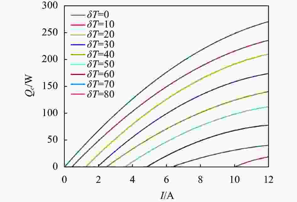
图 10 TEC制冷量与输入电流关系
Figure 10. Relationship between TEC cooling capacity and input current
-
设计选用的TEC控制器基本参数如表5所示,其中:VIN为温控模块的电源电压,V;CH为温控模块的控温通道个数;VOUT为温控模块输出电压,V;IOUT为温控模块输出电流,A;Dimensions为温控模块的外形尺寸,mm3;下标max表示最大。
表 5 TEC控制器的基本参数
Table 5. Basic parameters of the temperature control module of TEC
Parameter Numerical value VIN/V 24 CH 1 VOUTmax/V 19.2 IOUTmax/A 15 Dimensions/mm3 $ 55 \times 95 \times 28 $ -
寄生传热是指温度较高的器件通过辐射及热传导的方式向温度较低的器件传热。为了保证TEC热排散系统的制冷性能,必须减少寄生传热。因此,在热排散系统中外循环水路的结构件采用隔热设计的同时,仅采用六颗碳钢螺丝钉固定。
-
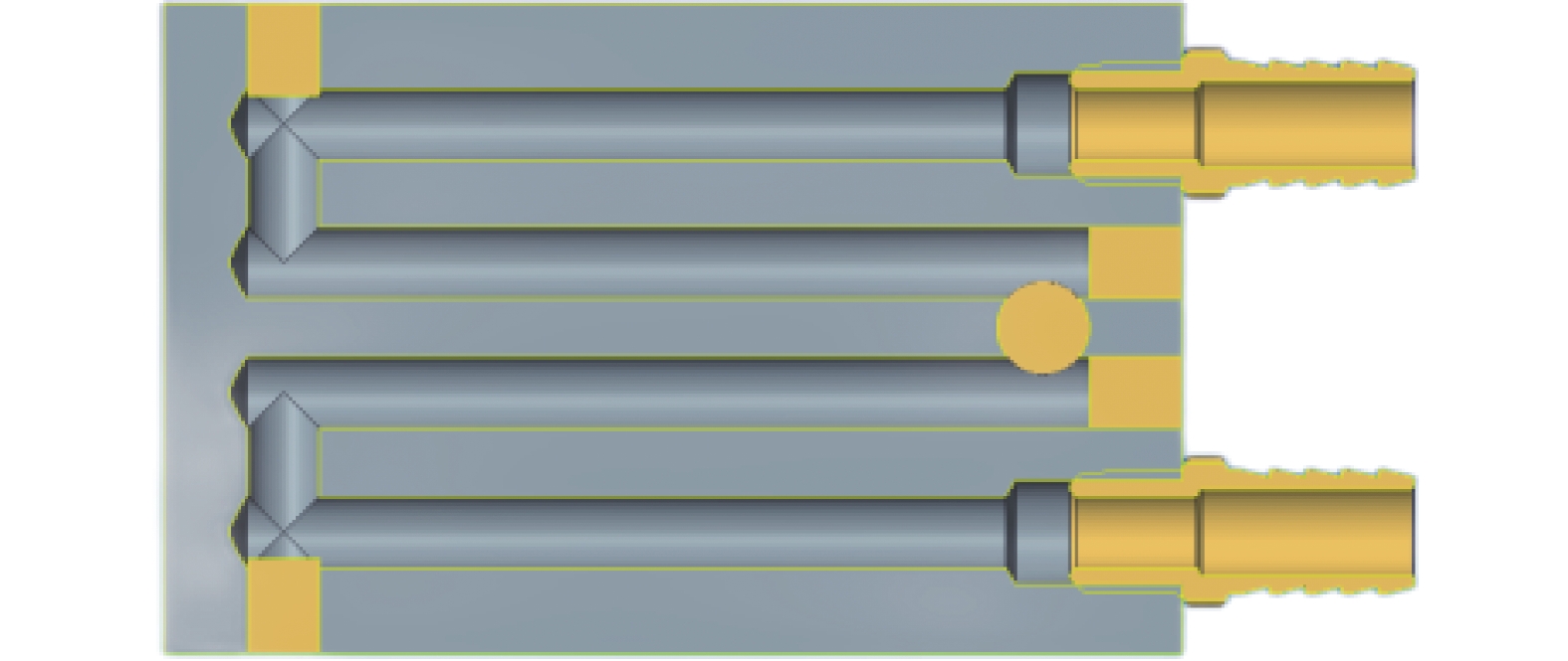
考虑到成本问题,设计的冷板换热器三维截面图如图11所示。该冷板换热器除长度为100 mm外,其他参数与DUT热电制冷组件中设计的水冷头完全一致。采用Flow Simulation对其内部流体流速进行仿真,该软件是利用经检验的计算流体力学(CFD)技术计算而实现仿真的,最终结果如图12所示[18]。

图 11 冷板换热器三维截面图
Figure 11. 3D section diagram of cold plate heat exchanger
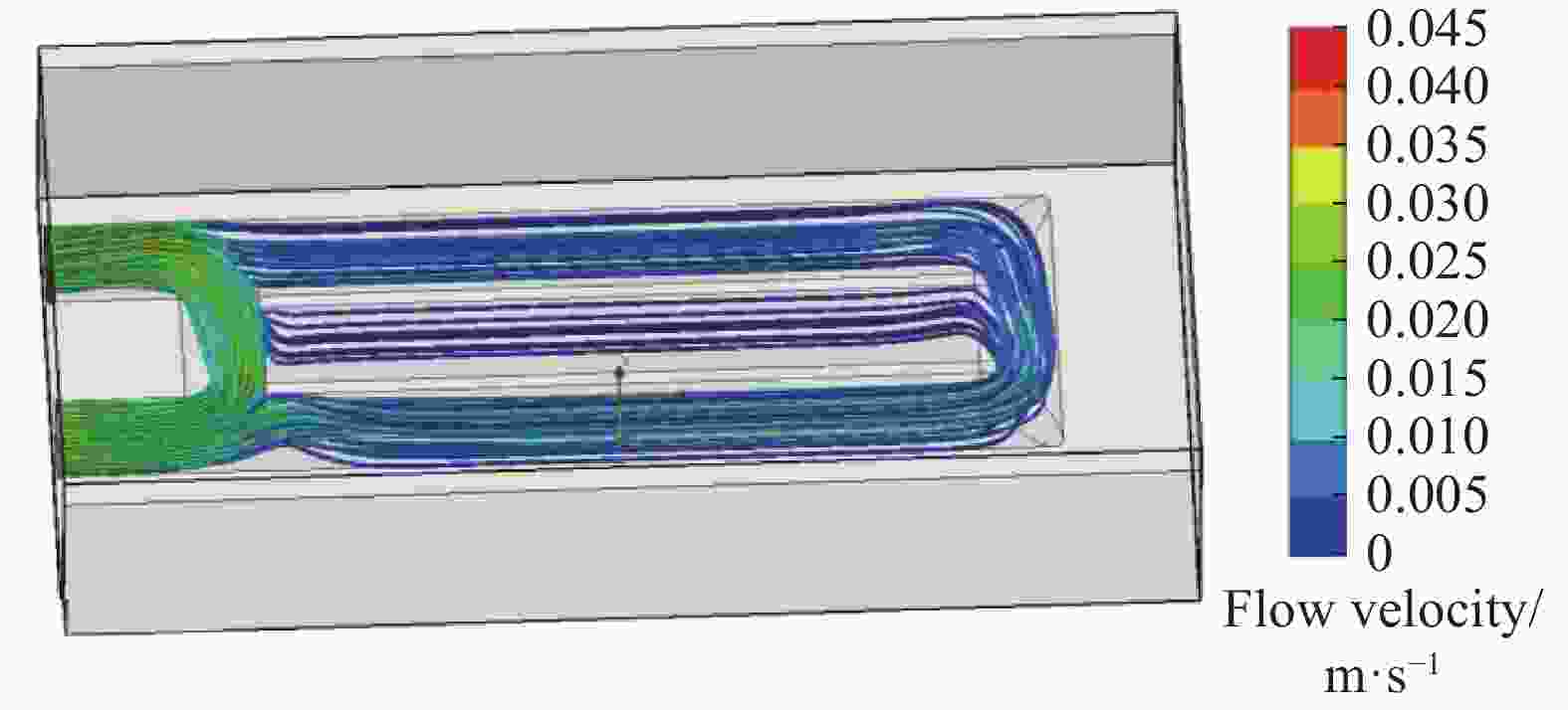
图 12 冷板内流体流速仿真
Figure 12. Simulation of fluid velocity in cold plate
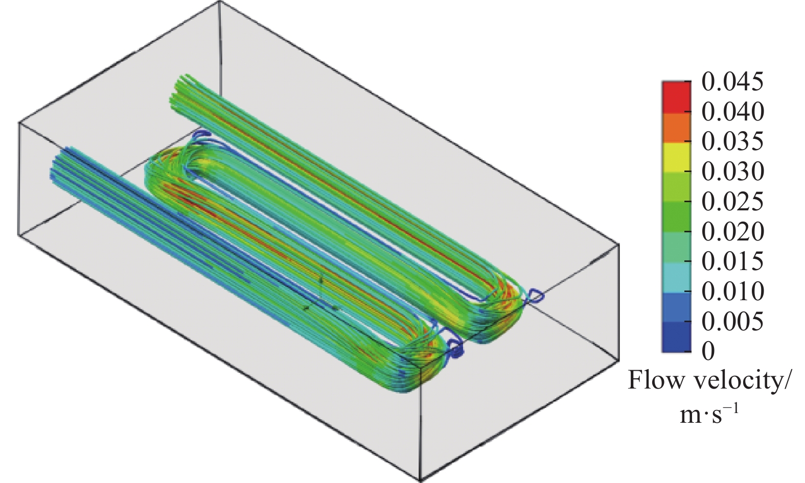
根据图12中的流体仿真结果可知,流体在该结构中的流速基本小于0.02 m/s,即水路结构不利于液体的流通,会影响冷板的散热效果。故优化水路的三维截面图如图13所示,其内部流体流速仿真结果如图14所示。
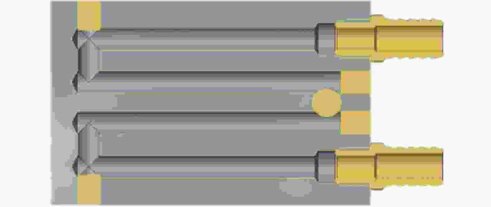
图 13 优化后的冷板换热器的三维截面图
Figure 13. 3D section diagram of optimized cold plate heat exchanger

图 14 优化后的冷板换热器流量仿真模型
Figure 14. The optimized fluid flow velocity simulation model of cold plate heat exchanger
根据图14可知,优化后的冷板换热器的水路可以保证流体在其中的流速大于0.02 m/s,该水路结构可用。
图15为TEC的热端热量与电流的关系曲线。取输入电流8.5 A,根据图10可以得出控温TEC的制冷量为90 W;此时TEC热端热量可以根据图15得到,为275 W。

图 15 TEC热端热量与输入电流关系
Figure 15. Relationship between the heat of the hot end of TEC and the input current
为验证TEC的数量是否与制冷效率成正相关,故在TEC热控系统中分别选取六片及八片TEC来制冷并相应地增加风扇数量。但考虑到噪音及体积因素,风扇数量最多为六个。每组环境分别测量10组并将实验结果取平均值。结果如表6所示。
表 6 不同数量的TEC的升降温时间
Table 6. Temperature rise and fall time of different number of TECs
The number of TEC/pcs The number of fans/pcs The duration of temperature rise/s The duration of temperature decrease/s 6 3 87 95 8 6 130 150 根据相关设计经验,结合所用TEC的综合制冷系数(Coefficient of Performance, COP)最大为0.5。最终在TEC热排散系统中使用四片TEC来给外循环水冷夜降温,TEC的热端用液冷的方式散热,TEC组直接由24 V、10 A供电。供电电路如图16所示。
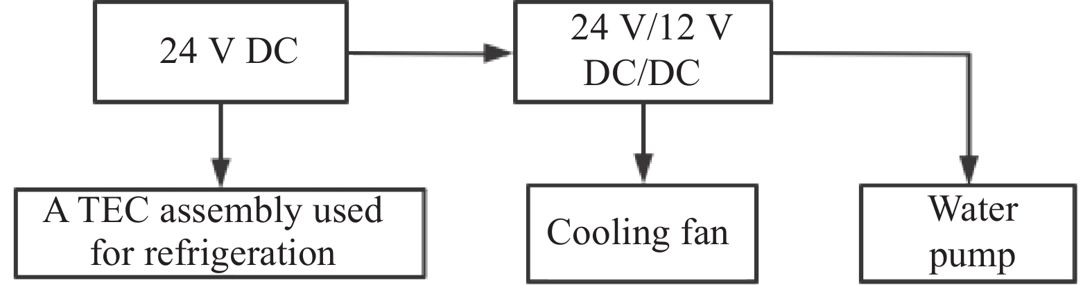
图 16 TEC热排散系统供电电路
Figure 16. Power supply circuit for TEC cooling system
由于综合考虑噪音、体积、供电总功率等问题,选取的水泵参数如表7所示。TEC热排散系统达到稳态后,TEC的热端温度可达到47 ℃,冷端温度为−2.5 ℃。内循环水路水温为45 ℃,外循环水路水温为−0.5 ℃,即TEC双面温差约为50 ℃。结合图10可知,每一片TEC的制冷量为100 W;结合图15可知,每一片TEC的热端产热量约为310 W。
表 7 水泵参数
Table 7. Parameters of water pump
Parameter Numerical value Volum/mL 8890 Nominal voltage/V 12 Incoming current/A 1.5±10% Motor speed/rpm 4500±5% Lift/m 6±1 Quantity of flow/L·h−1 1200 Power/W 18 内循环水路的初始水温为27 ℃,最终系统达到稳态时,内循环水路水温稳定在45 ℃,所以风排和风扇散去的总能量为:
$$ Q = c \cdot m \cdot \Delta T $$ (2) 式中:Q为散掉的总能量;C为水冷液的比热容;m为水冷液的体积流量;
$ \Delta T $ 为水冷液温升。结合公式(2)中的Q并综合考虑噪声、体积、效率及额定功率,最终选用的风排和风扇的参数分别如表8和表9所示。图17为最终设计出的热排散系统的简化结构图;图18为热排散系统内部风路仿真图;图19为热排散系统实物图;图20为热排散系统与误码仪搭建的光模块测试环境实物图。
表 8 风排参数
Table 8. Parameters of the air exhaust
Parameter Numerical value Size/mm3 $ 391 \times 121 \times 45 $ Number of pipes/bar 12×2 Diameter of fans/cm 12 表 9 风扇参数
Table 9. Paremeters of the fan
Parameter Numerical value Size/mm3 $ 120 \times 120 \times 38 $ Working voltage/V 12 Noise/dBA 55.5 Rated power/W 12.6 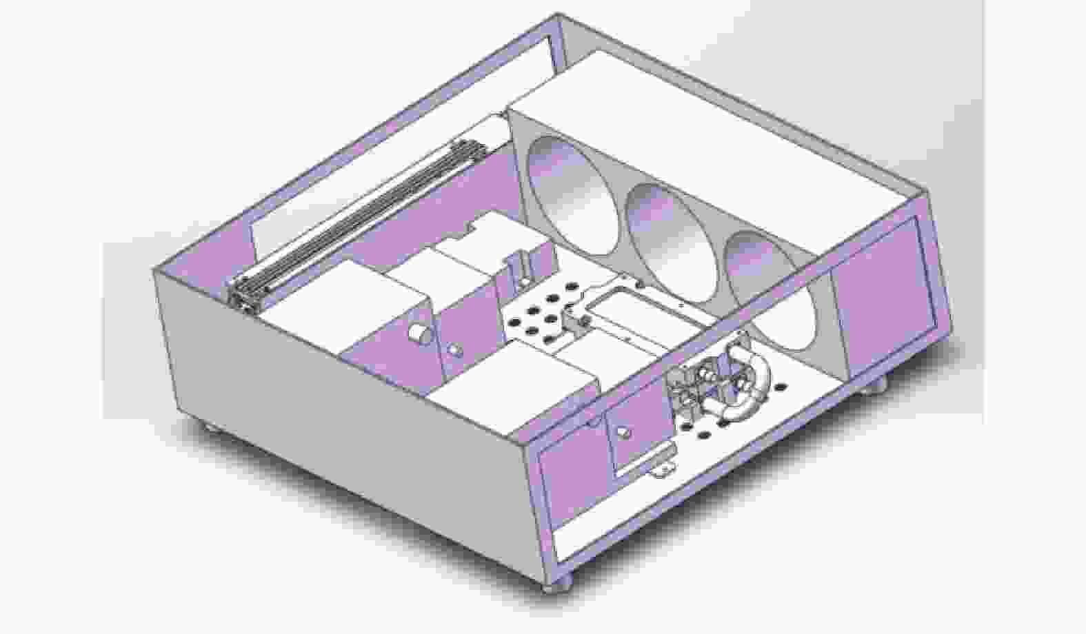
图 17 热排散系统结构图
Figure 17. Structure drawing of the heat dissipation system

图 18 热排散系统内部风路仿真
Figure 18. Simulation of air path inside heat dissipation system
图 19 热排散系统实物
Figure 19. Physical view of the heat dissipation system

图 20 热排散系统与误码仪共同搭建的测试平台
Figure 20. Test platform built by heat dissipation system and BERT instrument
-
根据前述元件选取及仿真模型搭建实验平台、实验装置。因为模块自身会有热量产生,所以通常情况下不考虑热控系统对升温效率的影响。故首先验证TEC热控系统可以使控温TEC在无负载情况下能达到的极限温度是否低于目标值,即低于−20 ℃,实验验证结果如图21所示。在无负载的情况下,经充分预冷,控温TEC的制冷面的极限低温为−31.1 ℃,同时满足制冷需求,TEC热控系统可用。
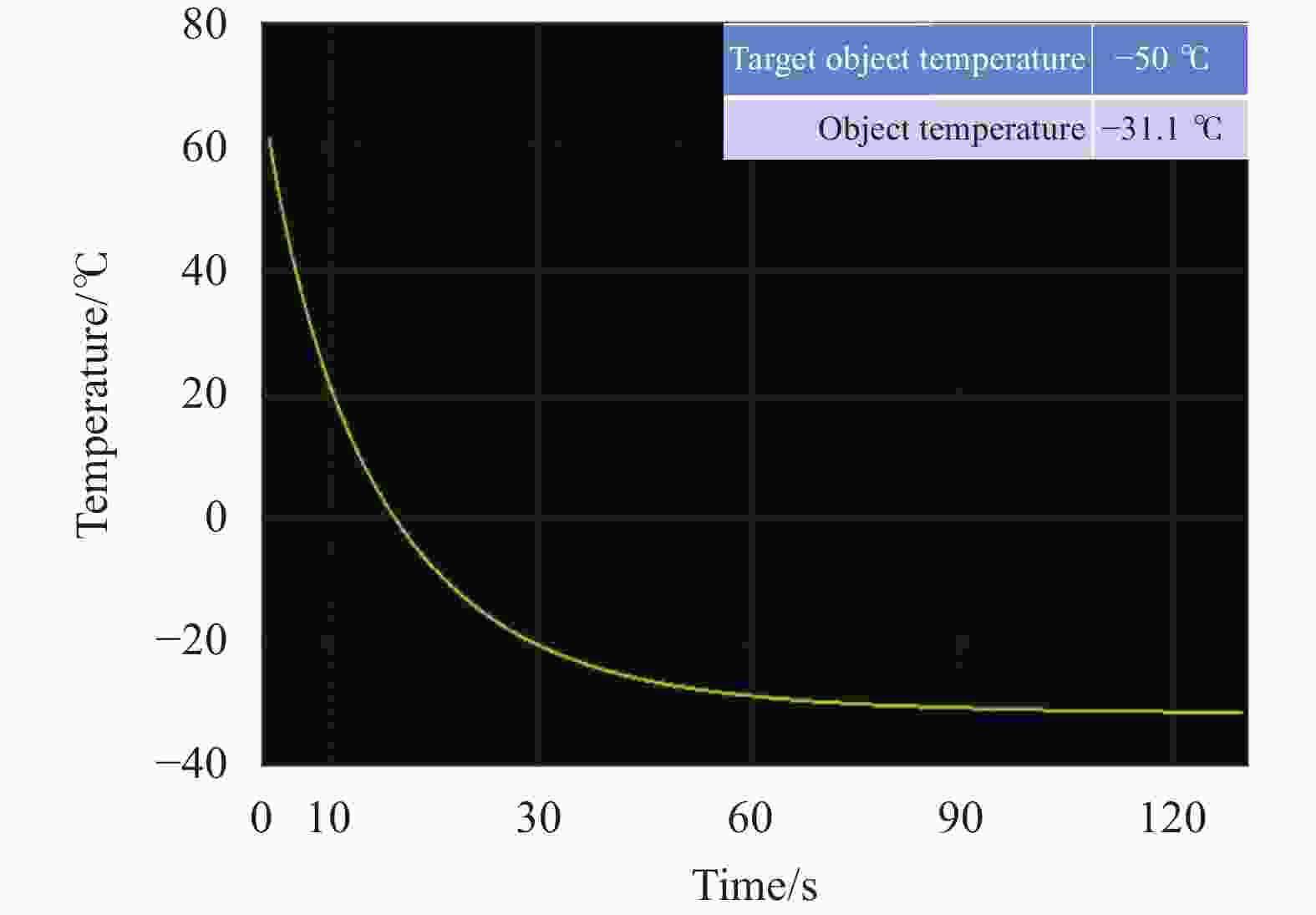
图 21 控温TEC制冷端极限温度
Figure 21. Limit temperature of TEC cooling surface for temperature control
-
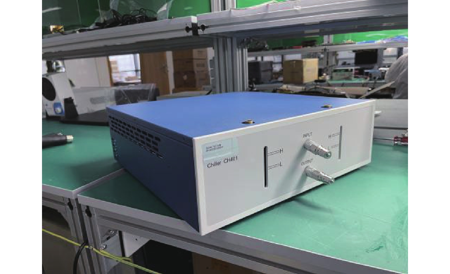
根据MSA多源协议QSFP-28和QSFP-DD封装模式的高速通信光模块的功率分别为7 W和14 W,但通常厂商为了降低功率,会将5 W和12 W作为模块的出厂标准。而MAS多源协议中将1.5 W定为SFP28的功率,厂家在出厂时会将功率降低到0.9 W。在功率上来估算,热控系统只要满足对单个QSFP-DD封装类型的光模块的升降温需求,那么在保证DUT测试板规格不变的条件下就可以同时并行测试两枚QSFP-28封装类型的光模块,四枚SFP28的光模块,大大提高了光模块的测试效率。在热控系统与水冷机的温循效率对比实验中所用的模块主要参数如表10所示。表中:“xxxG BASE”表示该产品支持和基于xxxG的应用环境;LR4表示传输距离为10 km,通道数为四个;IR4表示传输距离为2 km,通道数为四个。
表 10 实验所用模块主要参数
Table 10. Main parameters of the optical module used in the experiment
Type Type of module Central wavelength/nm QSFP-DD 400 G BASE LR4 1310 QSFP-28 100 G BASE IR4 1310 -
首先打开热排散系统及水冷机分别预冷30 min,然后打开热控系统中的DUT热电制冷器组件及TEC控制器,通过TEC控制器将两套系统中的热电制冷组件分别降温到−20 ℃后,用上位机软件读取模块壳温是否到达0 ℃。待模块壳温到达0 ℃,设置热电制冷组件升温到75 ℃,过程中通过上位机软件监控并记录模块壳温到达65 ℃的时间;之后重新控制热电制冷组件降到−20 ℃,监测并记录模块壳温达到0 ℃的时间,重复步骤并记录10组数据。
热控系统与水冷机对QSFP-DD的升降温效率对比结果如表11及图22所示。结合对比数据可知,热控系统的升温控温效率比水冷机慢约10 s,在可工程允许范围内。
表 11 QSFP-DD的升降温效率对比
Table 11. Comparison of heating and cooling efficiency of QSFP-DD
Number of tests The duration of
temperature rise/sThe duration of
temperature decrease/sThermal control system Water-cooling machine Thermal control system Water-cooling machine 1 101 93 95 93 2 99 95 96 93 3 99 90 95 93 4 103 91 95 93 5 100 90 95 92 6 102 89 95 92 7 98 92 95 93 8 102 90 94 92 9 101 93 96 92 10 103 91 95 92 Mean value 100.8 91.4 95.1 92.5 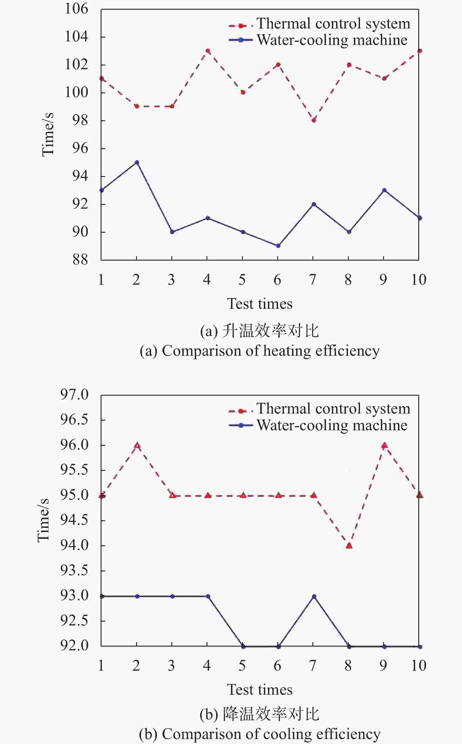
图 22 QSFP-DD的升降温效率对比
Figure 22. Comparison of heating and cooling efficiency of QSFP-DD
-
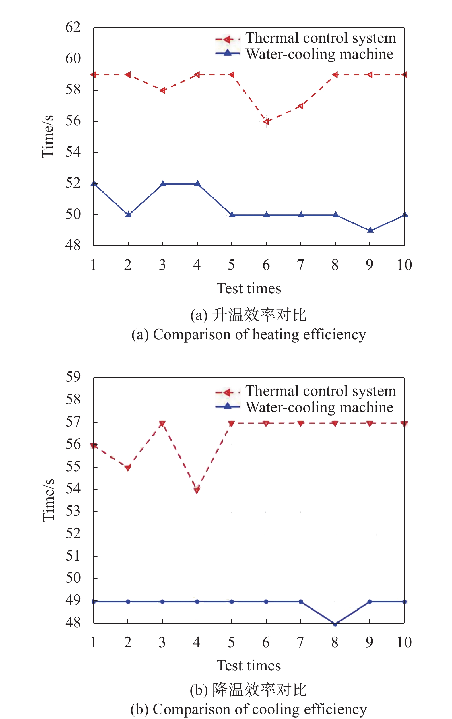
测试方式与上小节一致,故在此不过多赘述。热控系统与水冷机对两枚QSFP-28的升降温效率对比结果如表12及图23所示。结合对比数据可知,热控系统的升温控温效率比水冷机慢约10 s,在工程允许范围内。
表 12 QSFP-28的升降温效率对比
Table 12. Comparison of heating and cooling efficiency of QSFP-28
Number of tests The duration of
temperature rise/sThe duration of
temperature decrease/sThermal control system Water-cooling machine Thermal control system Water-cooling machine 1 59 52 56 49 2 59 50 55 49 3 58 52 57 49 4 59 52 54 49 5 59 50 57 49 6 56 50 57 49 7 57 50 57 49 8 59 50 57 48 9 59 49 57 49 10 59 50 57 49 Mean value 58.4 50.5 56.4 48.9 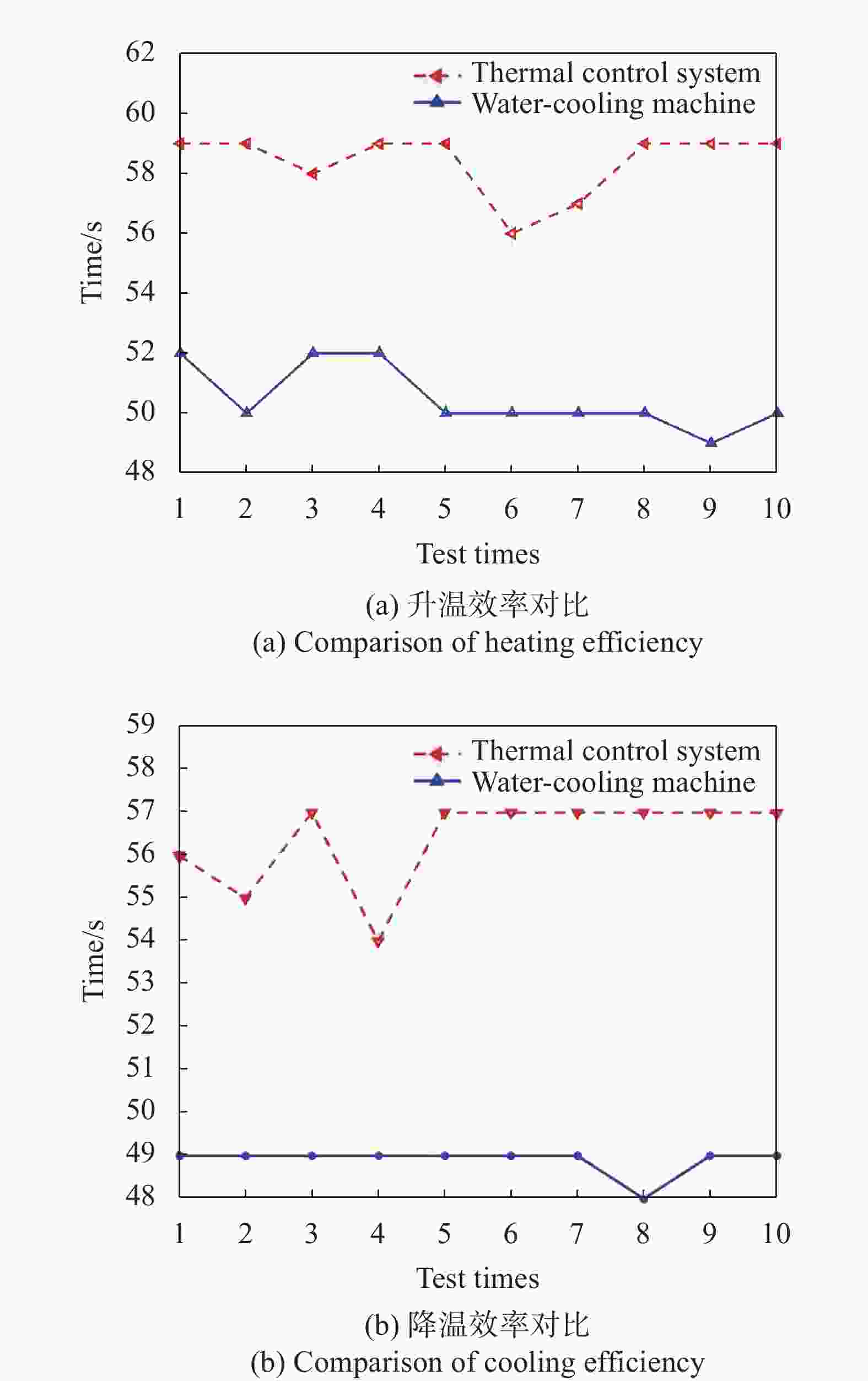
图 23 QSFP-28的升降温效率对比
Figure 23. Comparison of heating and cooling efficiency of QSFP-28
-
文中根据现代高速通信光模块的生产测试需求设计了高速通信光模块热控系统,并介绍了热控系统的结构和工作原理;然后设计了DUT热电制冷组件并使用Flotherm验证了其制冷效果;设计了热排散系统,进行了内部风路仿真;最后,将热控系统与水冷机进行升降温效率对比。实验结果证明:热控系统基本满足对常用封装方式的高速通信光模块的控温需求,且相对于水冷机而言,具有小型化、低噪音、零震动的优势。热控系统对QSFP-DD封装模式的光模块升降温时间可以控制在110 s内;对QSFP-28封装模式的光模块升降温时间可以控制在60 s内。相较于水冷机对光模块的控温效率而言,热控系统整体比水冷机慢10 s,但是热控系统的体积是水冷机的三分之一,且零震动、低噪音,满足模块极端温度测试的控温效率需求,并且适用于光模块功能的集成化测试。
Design of thermal control system for high-speed communication optical module
-
摘要: 为了测试高速通信光模块在极端环境下的工作性能,并提升其出厂测试效率,设计了高速通信光模块热控系统。使用该系统不仅可以实现单独测试QSFP-DD封装模式的光模块,还可以实现双通道并行测试QSFP-28封装模式的光模块,成功使光模块测试效率提升一倍。首先,根据半导体制冷器的特性设计了待测试件热电制冷器组件,Flotherm的仿真结果表明热电制冷器组件可用。接着,根据半导体制冷器的原理及特性,设计了热排散系统。最后,将热控系统与水冷机的控温效率和效果做对比。实验结果表明:热控系统可以在110 s内实现光模块壳温在0~65 ℃之间的快速调控。热控系统基本满足对常用封装方式的高速通信光模块的控温需求,且相对于水冷机而言,具有小型化、低噪音、零震动的优势,更利于光模块集成化测试。Abstract:
Objective As the communication rate increases, the power consumption of optical modules increases. Therefore, the heat dissipation environment of optical modules must be ensured. In order to ensure that the optical module can still maintain good performance under extreme environment, it is necessary to add extreme temperature cycle experiment in the delivery test of the optical module. With the increasing demand for optical modules, improving the efficiency of optical module delivery test has become the first engineering problem to be solved. Therefore, the design of the thermal control system for the high-speed communication optical module is important. Methods First, according to the characteristics of the semiconductor cooler, the thermoelectric cooler assembly of the device under test was designed (Fig.3-4) and the results of Foltherm simulation indicate the availability of thermoelectric refrigeration components (Fig.6-7). Then, according to the principle and characteristics of the semiconductor refrigerator, the heat dissipation system is designed (Fig.17-19). Finally, the temperature control efficiency and the effect of the thermal control system and the water cooler are compared. Results and Discussions The thermal control system of high-speed communication optical module uses a semiconductor cooler as the refrigeration unit, and the rise and fall time of the optical module in QSFP-DD packaging mode can be controlled within 110 s (Tab.11 and Fig.24). The rise and fall time of the optical module in QSFP-28 encapsulation mode can be controlled within 60 s (Tab.11 and Fig.25). The effect of temperature control is good, and the high-speed communication optical module manufacturers can analyze the performance of the optical module within the operating temperature range of commercial grade. The system is mainly composed of the device under test, thermoelectric cooler, the fixture, the controller of the semiconductor cooler and the heat dissipation system. Among them, the thermoelectric cooler assembly of the device under test is made up of the cylinder bracket and the cold plate radiator mounting box, which effectively reduces the heat leakage (Fig.3-4); Flotherm software is used to establish a thermal simulation model of cold plate heat exchanger in thermoelectric refrigeration components. The simulation results show that the module shell temperature can be stabilized at −0.382 ℃, and the cold plate heat exchanger can meet the requirements (Fig.6-7). And in the meantime, Flow Simulation is adopted to optimize the water flow of the cold plate heat exchanger in the heat dissipation system. The flow velocity of the optimized water flow in the cold plate heat exchanger is greater than 0.02 m/s (Fig.14), and the optimized water structure is available. This system has the advantages of little vibration and low noise, and only one-third volume of the water cooler (Fig.20). Meanwhile, this thermal control system basically meets the temperature control requirements for the high-speed communication optical modules with the common packaging methods. Conclusions The time of temperature control of the optical module with the thermal control system is 10 s longer than that with the water cooler. But it has the advantages of miniaturization, low noise and zero vibration, which is more conducive to the integrated testing of optical modules. Using this system can not only test the optical modules in the QSFP-DD package mode independently, but also realizes the dual-channel parallel test of the optical modules in the QSFP-28 package mode to double the test efficiency of optical module. -
图 4 DUT热电制冷组件封装三维模型
Figure 4. Package 3D model of DUT thermoelectric refrigeration components
图 6 冷板换热器进出口水冷液温度
Figure 6. Cold plate heat exchanger inlet and outlet water cooling temperature
图 10 TEC制冷量与输入电流关系
Figure 10. Relationship between TEC cooling capacity and input current
图 13 优化后的冷板换热器的三维截面图
Figure 13. 3D section diagram of optimized cold plate heat exchanger
图 14 优化后的冷板换热器流量仿真模型
Figure 14. The optimized fluid flow velocity simulation model of cold plate heat exchanger
图 15 TEC热端热量与输入电流关系
Figure 15. Relationship between the heat of the hot end of TEC and the input current
图 20 热排散系统与误码仪共同搭建的测试平台
Figure 20. Test platform built by heat dissipation system and BERT instrument
图 21 控温TEC制冷端极限温度
Figure 21. Limit temperature of TEC cooling surface for temperature control
图 22 QSFP-DD的升降温效率对比
Figure 22. Comparison of heating and cooling efficiency of QSFP-DD
图 23 QSFP-28的升降温效率对比
Figure 23. Comparison of heating and cooling efficiency of QSFP-28
表 1 TEC热排散系统设计指标
Table 1. Design indicators of TEC cooling system
Temperature settings for TEC/℃ Shell temperature of the module/℃ Time/s −20-75 0-65 120 75-−20 65-0 120  下载: 导出CSV
表 2 冷板换热器相关尺寸
Table 2. Relevant dimensions of cold plate heat exchanger
Name Size/mm Name Size/mm Total height 17 Total length 50 Diameter of inlet 6 Diameter of outlet 6 Total width 50 Diameter of pipe 6 Spacing of pipes 3.5 Width of the left and right boundaries 7.75 Width of the front and back boundaries 6 Width of the upper and lower boundaries 5.5
下载: 导出CSV
表 3 30 ℃水的物性参数
Table 3. Physical parameters of water at 30 ℃
Parameter Value Thermal conductivity ${\lambda _f}/{\rm{W} }\cdot ({\rm{m} } \cdot {\rm{K} })^{-1}$ $ 0.62 $ Kinematic viscosity of fluid ${\upsilon _f}/{ {\rm{m} }^2} \cdot{\rm{s} ^{-1} }$ $ 0.805 \times {10^{{{ - }}6}} $ Fluid density $\;{\rho _f}/{\rm{kg} } \cdot { {\rm{m} }^{-3} }$ $ 995.4 $ Specific heat ${C_p}/{\rm{J} }\cdot({\rm{kg} } \cdot {\rm{K} })^{-1}$ $ 4.17 \times {10^3} $ Prandtl number Pr $ 5.42 $
下载: 导出CSV
表 4 TEC的基本参数
Table 4. Basic parameter of TEC
Name Numerical value Conditions for testing ${I_{\max } }/{\rm{A}}$ 15 $ {Q}_{c}=0,\delta T=\delta {T}_{\mathrm{max}},{T}_{h}=50 $ ℃${U_{\max } }/{\rm{V}}$ 37.4 $ {Q}_{c}=0,I={I}_{\mathrm{max}},{T}_{h}=50 $ ℃$ \delta {T}_{\mathrm{max}}/ $ ℃78 $ {Q}_{c}=0,I={I}_{\mathrm{max}},{T}_{h}=50 $ ℃${Q_{c\max } }/{\rm{W}}$ 294 $ {Q}_{c}=0,\delta T=0,{T}_{h}=50 $ ℃$ {T}_{h\mathrm{max}}/ $ ℃200 Instant
下载: 导出CSV
表 5 TEC控制器的基本参数
Table 5. Basic parameters of the temperature control module of TEC
Parameter Numerical value VIN/V 24 CH 1 VOUTmax/V 19.2 IOUTmax/A 15 Dimensions/mm3 $ 55 \times 95 \times 28 $
下载: 导出CSV
表 6 不同数量的TEC的升降温时间
Table 6. Temperature rise and fall time of different number of TECs
The number of TEC/pcs The number of fans/pcs The duration of temperature rise/s The duration of temperature decrease/s 6 3 87 95 8 6 130 150
下载: 导出CSV
表 7 水泵参数
Table 7. Parameters of water pump
Parameter Numerical value Volum/mL 8890 Nominal voltage/V 12 Incoming current/A 1.5±10% Motor speed/rpm 4500±5% Lift/m 6±1 Quantity of flow/L·h−1 1200 Power/W 18
下载: 导出CSV
表 8 风排参数
Table 8. Parameters of the air exhaust
Parameter Numerical value Size/mm3 $ 391 \times 121 \times 45 $ Number of pipes/bar 12×2 Diameter of fans/cm 12
下载: 导出CSV
表 9 风扇参数
Table 9. Paremeters of the fan
Parameter Numerical value Size/mm3 $ 120 \times 120 \times 38 $ Working voltage/V 12 Noise/dBA 55.5 Rated power/W 12.6
下载: 导出CSV
表 10 实验所用模块主要参数
Table 10. Main parameters of the optical module used in the experiment
Type Type of module Central wavelength/nm QSFP-DD 400 G BASE LR4 1310 QSFP-28 100 G BASE IR4 1310
下载: 导出CSV
表 11 QSFP-DD的升降温效率对比
Table 11. Comparison of heating and cooling efficiency of QSFP-DD
Number of tests The duration of
temperature rise/sThe duration of
temperature decrease/sThermal control system Water-cooling machine Thermal control system Water-cooling machine 1 101 93 95 93 2 99 95 96 93 3 99 90 95 93 4 103 91 95 93 5 100 90 95 92 6 102 89 95 92 7 98 92 95 93 8 102 90 94 92 9 101 93 96 92 10 103 91 95 92 Mean value 100.8 91.4 95.1 92.5
下载: 导出CSV
表 12 QSFP-28的升降温效率对比
Table 12. Comparison of heating and cooling efficiency of QSFP-28
Number of tests The duration of
temperature rise/sThe duration of
temperature decrease/sThermal control system Water-cooling machine Thermal control system Water-cooling machine 1 59 52 56 49 2 59 50 55 49 3 58 52 57 49 4 59 52 54 49 5 59 50 57 49 6 56 50 57 49 7 57 50 57 49 8 59 50 57 48 9 59 49 57 49 10 59 50 57 49 Mean value 58.4 50.5 56.4 48.9
下载: 导出CSV
-
[1] Zhang Taolue, Li Qibo, Shankaran G, et al. Fan cooling investigation for high-speed electronic interconnect [EB/OL]. (2022-07-07) [2022-09-02]. https://doi.org/10.1080/01457632.2022.2093530. [2] 徐德胜. 半导体制冷与应用技术[M]. 上海: 上海交通大学出版社, 1992. [3] Goldsmid H J. Electronic Refrigeration[M]. Berlin: Springer, 1986. [4] Rowe D M, Pollock D D, Stockholm J G, et al. CRC Handbook of Thermoelectrics[M]. Boca Raton: CRC Press, 2018. [5] Kaushik S C, Bhardwaj S C. Theoretical analysis of ammonia-water absorption cycles for refrigeration and space conditioning systems [J]. International Journal of Energy Research, 1982, 6(3): 205-225. doi: 10.1002/er.4440060302 [6] Pang Y F. The theoretical analysis and experimental research on the optimal condition of semiconductor refrigeration [J]. IOP Conference Series: Earth and Environmental Science, 2016, 40(1): 340-348. [7] Zhang Bo, Wang Yaxiong. An experimental investigation on a novel liquid thermoelectric cooling device [J]. CIESC Journal, 2014, 65(9): 3441-3446. (in Chinese) doi: 10.3969/j.issn.0438-1157.2014.09.018 [8] Liu Xiaoping, Cao Xu, Li Juxiang. Experimental research of heat pipe dissipater at the hot side of semiconductor [J]. Bulletin of Science and Technology, 2016, 32(7): 113-116. (in Chinese) doi: 10.3969/j.issn.1001-7119.2016.07.023 [9] Sun Zhe, Huang Xiang, Liu Jiali. Experimental study on split evaporative air conditioner of evaporative cooling and semiconductor refrigeration [J]. Fluid Machinery, 2013, 41(9): 61-65. (in Chinese) doi: 10.3969/j.issn.1005-0329.2013.09.014 [10] Li Jianglan, Shi Yunbo, Zhao Pengfei, et al. High precision thermostat system with TEC for laser diode [J]. Infrared and Laser Engineering, 2014, 43(6): 1745-1749. (in Chinese) doi: 10.3969/j.issn.1007-2276.2014.06.009 [11] Liu Gang, Tang Xiaojun, Zhao Hong, et al. New designs and CFD numerical simulations for solid-state laser heat sink [J]. Infrared and Laser Engineering, 2014, 43(4): 1111-1116. (in Chinese) doi: 10.3969/j.issn.1007-2276.2014.04.016 [12] Xu Nana, Yu Feng, Zhou Zhenhua. Thermal design and validation of a geosynchronous orbit infrared camera [J]. Infrared and Laser Engineering, 2021, 50(9): 20210056. (in Chinese) doi: 10.3788/IRLA20210056 [13] 刘宁. 液冷系统中流体流动及换热特性的研究[D]. 南京理工大学, 2013. Liu Ning. Research on fluid flow and heat transfer characteristics of liquid-cooling system[D]. Nanjing: Nanjing University of Science & Technonlogy, 2013. (in Chinese) [14] Zhang H Y. A general approach in evaluating and optimizing thermoelectric coolers [J]. International Journal of Refrigeration, 2010, 33(6): 1187-1196. doi: 10.1016/j.ijrefrig.2010.04.007 [15] Luo Z. A simple method to estimate the physical characteristics of a thermoelectric cooler from vendor datasheets [J]. Electronics Cooling, 2008, 14(3): 22-27. [16] Yang Wengang, Fan Xuewu, Wang Chenjie, et al. Design and test of thermo electric cooling system for space based telescope detector assembly [J]. Acta Photonica Sinica, 2020, 49(8): 0822001. (in Chinese) [17] Astrain D, Vi N J G, Dominguez M. Increase of COP in the thermoelectric refrigeration by the optimization of heat dissipation [J]. Applied Thermal Engineering, 2003, 23(17): 2183-2200. doi: 10.1016/S1359-4311(03)00202-3 [18] DS SolidWorks®公司. SolidWorks® Flow Simulation教程[M]. 北京: 机械工业出版社, 2013. -

 点击查看大图
计量
- 文章访问数: 130
- HTML全文浏览量: 21
- PDF下载量: 35
- 被引次数: 0


