


-
作为近年来快速发展的一种新型武器类型,巡飞弹可将侦察、引导、打击、评估等多项作战任务进行组合式协同实施,可大幅缩短作战响应时间,拓展了部队的作战模式,也有效提升了部队作战能力[1-2]。巡飞弹载光电载荷作为巡飞弹武器系统的关键设备,迎来了新的发展机遇,但同时也面临着新的设计挑战,急切需要采用先进设计方法提高其设计水平。
自1988年Bendsøe和Kikuchi提出基于均匀化的结构拓扑优化设计方法以来[3],拓扑优化设计方法已经取得了快速的发展,并在工程设计领域得到了广泛的应用。拓扑优化方法的本质,可看作在给定设计区域内材料最优分布的求解问题[4]。相比尺寸优化和形状优化,拓扑优化设计方法作为一种新型的概念设计方法,优化效果更加突出,已逐渐成为结构创新设计的一种重要方法。
近年来,拓扑优化方法被广泛应用于多种工程结构设计[5-9]。比如,李元等人利用拓扑优化方法对扫描反射镜进行了拓扑优化,得到了满足模态要求和镜面变形的轻量化结构[10]。刘仲宇等人利用拓扑优化方法对某红外导引头稳定平台主框架进行了拓扑优化设计,降低了结构质量,并提高了其一阶频率[11]。杨雪利用变密度拓扑优化方法实现了导引头承载件的轻量化设计[12]。王上等人利用拓扑优化方法实现了对一体化铝合金反射镜的刚度设计和轻量化设计[13]。鉴于拓扑优化方法良好的轻量化和高效承载设计效果,文中将拓扑优化方法拓展应用于新型巡飞弹载光电的结构设计,在保证结构力学性能的前提下,有效降低结构质量,提高巡飞弹载光电结构设计水平,提高系统作战效能。
-
某巡飞弹载光电载荷内部集成有可见光电视、红外热像仪、激光测照器等多个核心光电传感器,可为巡飞弹提供昼夜侦察和激光照射功能,作为一款多功能高精度巡飞弹载光电载荷,其在设计中需考虑多种严苛的冲击振动等环境条件,同时其体积质量等设计空间严重受限,因此,在设计过程中应极其注重结构的轻量化高效承载设计。
该巡飞弹载光电载荷的组成示意图如图1所示,主要包括方位轴系、俯仰轴系、光具座以及多个光电传感器等组成。图1中,TV表示可见光电视、IR表示红外热像仪、Laser表示激光测照器,三个传感器和光具座组成了光具座组件,作为方位轴系和俯仰轴系的负载。光电载荷通过方位轴系和俯仰轴系及其支撑结构组成的伺服稳定控制平台,实现对传感器光轴的高精度稳定和对目标的稳定跟踪和照射。

图 1 巡飞弹载光电载荷组成示意图
Figure 1. Schematic diagram of electro-optic systems for loitering munition
图1中光具座零件作为可见光电视、红外热像仪、激光测照器三个核心光电传感器的安装和支撑结构,是巡飞弹载光电载荷的关键结构,其设计的优良对于光电系统减重、伺服高精度稳定以及多传感器的光轴保持精度均具有重要的影响,可谓是巡飞弹载光电实现对目标精准照射功能的关键结构[14]。传统经验设计方法在面对此类设计问题时,通常具有设计周期长和设计效果难保证的问题。文中拟利用拓扑优化设计方法对该巡飞弹载光电光具座结构开展拓扑优化设计,实现光具座结构的高效力学承载设计,以满足巡飞弹载光电载荷的作战使用要求。
-
光具座材料为铝合金,根据使用要求和经验设计,在光具座设计空间内,通过减重孔和加强筋设计实现光具座的刚度设计和减重设计。根据经验设计完成的光具座设计方案质量为2.57 kg,之后利用有限元仿真分析对该光具座组件设计方案进行力学性能评估。
考虑工程应用过程中的计算效率,在光具座组件仿真分析前,首先需对其进行必要的模型简化,建立有效的有限元模型。由图1可见,光具座的主要负载为三个传感器,由于光具座相比传感器的刚度较大,因此为提高计算效率,可将三个传感器以及一个电路板分别简化为质量点,并按照各自的质心位置和固定方式与光具座进行连接。最终建立的光具座组件有限元模型如图2(a)及图2(b)所示,图中Mass point 1、2、3、4分别为可见光电视、激光测照器、红外热像仪和电路板的等效质量点。该有限元模型中,光具座结构被划分为431901个四面体网格单元,在计算效率和技术精度方面可取得较好的平衡。

图 2 光具座组件有限元模型:(a)视角1;(b)视角2
Figure 2. Finite element model of optical bench component: (a) View 1; (b) View 2
以图2所示光具座组件有限元模型为基础,对该光具座经验设计方案进行仿真分析。光具座组件在实际使用过程中需承受多种不同的冲击和振动等工况,根据以往大量设计经验,光具座结构的低阶模态频率和其在过载下的结构变形结果对光具座结构的静态和动态性能具有良好的表征作用,因此,文中开展的分析类型主要为模态分析和过载分析。在模态分析和过载分析中,按照光具座组件的实际安装方式,对光具座上下两端的螺纹孔区域进行固定约束,具体位置如图2(a)所示。
在模态分析中,无阻尼系统自由振动方程为:
$$ {\boldsymbol{M}}\ddot {\boldsymbol{x}}(t) + {\boldsymbol{Kx}}(t) = {\boldsymbol{0}} $$ (1) 式中:M为结构质量矩阵;K为结构刚度矩阵;x(t)为结构位移向量。
对图2中固定约束下的光具座组件开展模态分析,根据公式(1)进行求解可以得到系统的第i阶固有频率fi及其对应的第i阶振型向量
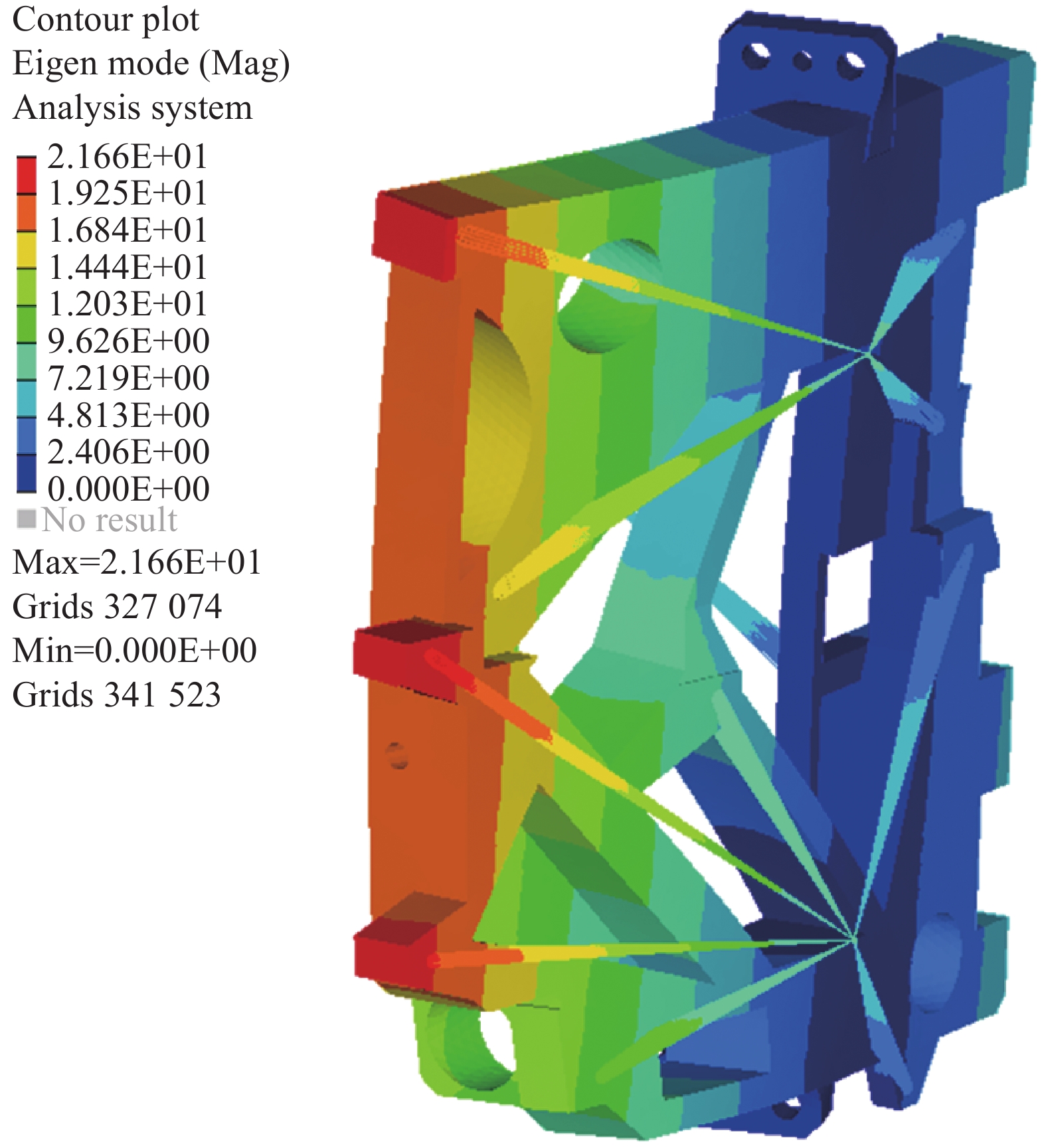
${{\boldsymbol{\phi}} _i} $ 。利用Altair HyperWorks软件对光具座组件开展模态分析,得到其前三阶模态频率分别为149.7、279.4、334.3 Hz,其一阶模态振型图如图3所示。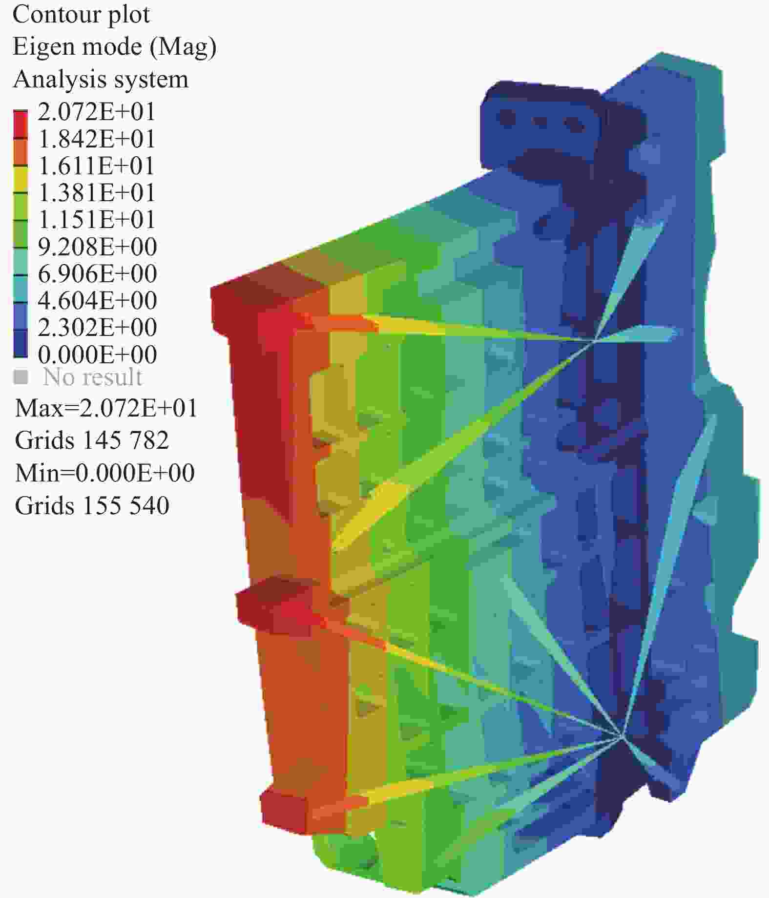
图 3 光具座组件一阶振型图
Figure 3. The first modal shape of optical bench component
在过载分析中,结构静力学方程为:
$$ {\boldsymbol{KU}} = {\boldsymbol{Ma}} $$ (2) 式中:U为过载分析时结构位移向量;a为过载分析加载的加速度载荷向量。
在过载分析下,利用结构柔顺度C表征结构的总体刚度,其值越小则表示其刚度越好,柔顺度C的计算公式如公式(3)所示:
$$ C = {{\boldsymbol{U}}^{\rm{T}}}{\boldsymbol{KU }}$$ (3) 利用Altair HyperWorks软件对光具座组件开展过载分析,分别对其在X、Y、Z三向40 g过载工况进行分析,得到光具座结构的最大位移分别为0.024、0.019、0.325 mm,其结构柔顺度分别为13.83、10.89、129.36 N·mm。
参照以往光电系统的成功设计方案,上述分析结果体现出的光具座结构特性能够满足该类光电设备的使用需求,但是其质量已超出系统分配指标,按照系统质量分解要求,光具座结构质量应当在2 kg以内。因此,文中拟采用拓扑优化方法,在力学性能基本不变的前提下,对该光具座结构进行轻量化设计。
-
根据不同的设计变量设置方法,拓扑优化方法可以分为不同的类型,其中以变密度法[15]为代表的拓扑优化方法发展迅速并且在工程中应用更为广泛。该类拓扑优化方法以有限元模型中单元的密度为变量,并通过材料插值模型,将单元的密度变量与单元的材料属性联系起来,从而使有限元模型中单元的有、无这种离散设计问题转化为关于密度的连续变量优化问题,材料插值模型的设置对中间密度值具有惩罚效果,从而促使单元密度逐渐靠近0或者靠近1。优化结果中,若密度为0表示该单元应从结构中被去除,密度为1则表示该单元应保留在结构中。
-
根据光具座设计需求和拓扑优化设计方法原理,文中建立了以光具座结构质量最小为目标,以光具座组件一阶模态频率和光具座组件在三向40 g过载工况下的柔顺度为约束的拓扑优化模型,优化模型如公式(4)所示:
$$ \left\{ \begin{array}{l} {\rm{find}}:\boldsymbol{\eta}=\left(\eta_1, \eta_2, \cdots, \eta_{{n}}\right)^{\mathrm{T}} \\ {\rm{min}}:{\rm mass}\\ {\rm{s.t}} \; \; {{{f}}}_{1} \geqslant 150 \; \text{Hz};\\ \qquad {C}_{{x}} \leqslant 13.83 \; {\rm{N }} \cdot {\rm{mm}};\\ \qquad {C}_{{{y}}} \leqslant 10.89 \;{\rm{ N}} \cdot {\rm{mm}};\\ \qquad {C}_{{{z}}} \leqslant 129.36 \; {\rm{N}} \cdot {\rm{mm}}; \end{array} \right. $$ (4) 式中:η为有限元模型单元密度向量,为拓扑优化的设计变量;n为有限元模型的单元数量;mass为光具座结构的质量;f1为光具座组件的一阶频率;Cx、Cy、Cz分别为光具座组件在X、Y、Z三向40 g过载下的柔顺度。
因此,文中建立的拓扑优化模型,其目标是光具座结构质量最小,其约束包含:其一阶频率不低于经验设计方案的一阶频率;其在X、Y、Z三向过载下的柔顺度分别不大于经验设计方案相应的柔顺度。
-
对公式(4)中的拓扑优化模型进行求解,经过19次优化迭代,得到收敛的优化结果如图4所示。根据优化结果,将低密度单元去除后,光具座结构的拓扑优化结果示意图如图5所示,初步观测可知拓扑优化得到的光具座结果具有良好的传力路径,具备形成最终设计方案的基本条件。

图 4 光具座拓扑优化结果单元密度示意图
Figure 4. Schematic diagram of topology optimized result for optical bench with element density
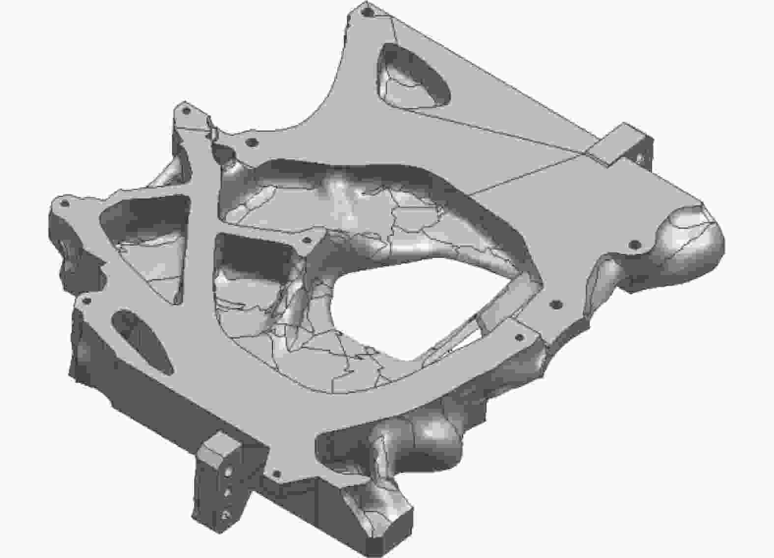
图 5 光具座拓扑优化结果示意图
Figure 5. Schematic diagram of topology optimized result of optical bench
拓扑优化过程中,优化目标函数以及约束函数的优化迭代曲线如图6所示。
由上述优化迭代曲线可见该光具座结构拓扑优化模型得到了有效的求解。优化结果中,一阶频率为153.71 Hz,X、Y、Z三向过载下的柔顺度分别为11.95、10.66、101.47 N·mm,满足设计约束,同时,光具座质量由2.57 kg优化为1.65 kg,具有良好的优化效果。
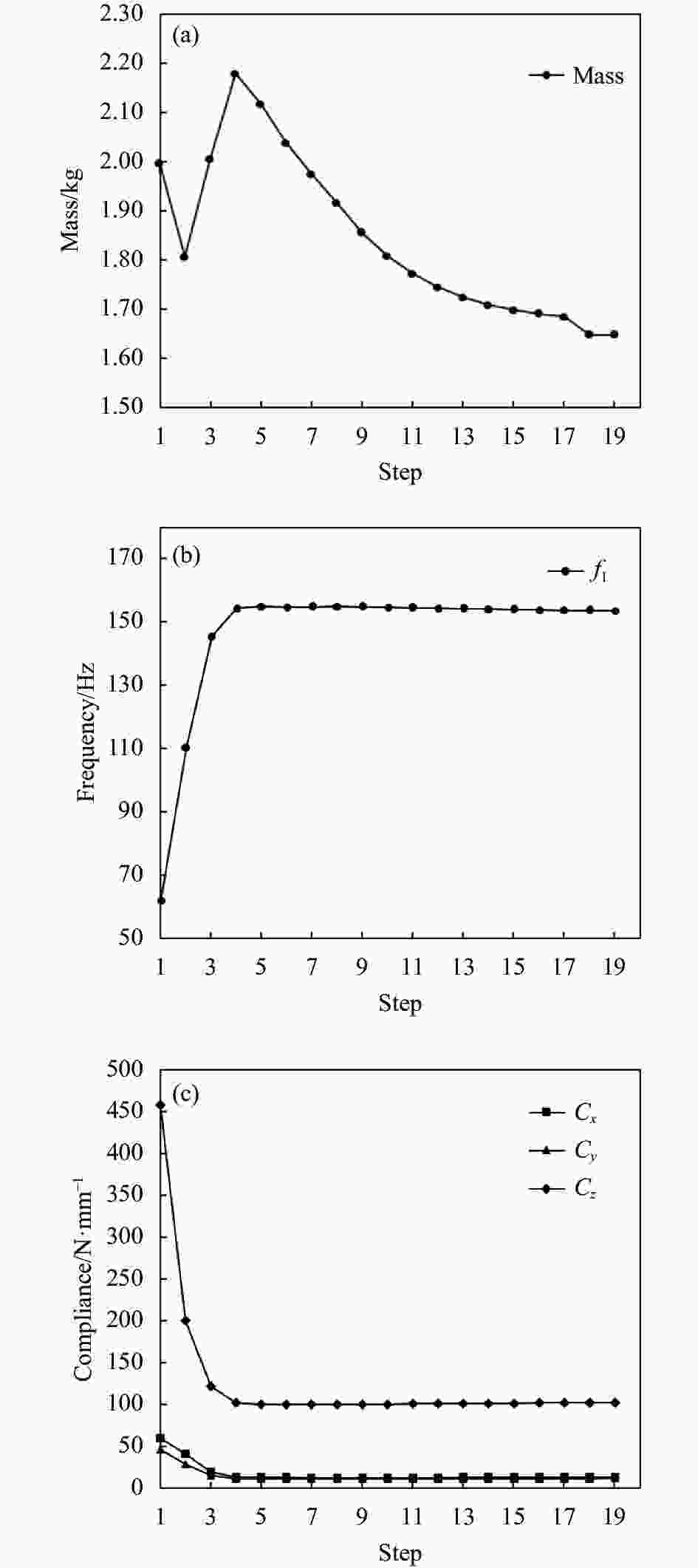
图 6 (a) 光具座质量的优化收敛曲线;(b)光具座组件一阶频率优化收敛曲线;(c)光具座组件柔顺度优化收敛曲线
Figure 6. (a) Optimized convergence curve of the optical bench mass; (b) Optimized convergence curve of f1 of optical bench component; (c) Optimized convergence of Cx, Cy, Cz of optical bench component
-
光具座结构拓扑优化完成后,为得到工程可用的结构,需要结合系统使用要求以及零件加工工艺性,对拓扑优化结果进行必要的几何重构。此处,利用UG建模软件对图5中拓扑优化结果进行几何重构,在重构过程中,基于拓扑优化结果,充分考虑光具座零件使用要求和机加制造要求,通过倒圆、补面、特征微调等多种手段,得到可用于机加制造的零件模型,其结果如图7(a)所示。光具座重构结构的质量为1.995 kg,大于初始拓扑优化结果,但是满足系统分配的光具座结构质量指标2 kg,因此其质量满足设计要求。对光具座重构结构进行有限元建模,结果如图7(b)所示。

图 7 (a)光具座重构结构几何模型;(b)光具座重构结构有限元模型
Figure 7. (a) Geometric model of reconstructed optical bench; (b) Finite element model of reconstructed optical bench
对图7(b)中光具座组件开展模态分析,光具座固定约束方式不变,得到其前三阶模态频率分别为154.3、290.9、298.1 Hz,其一阶模态振型图见图8。

图 8 优化重构后光具座组件一阶振型图
Figure 8. The first modal shape of optimized reconstructed optical bench component
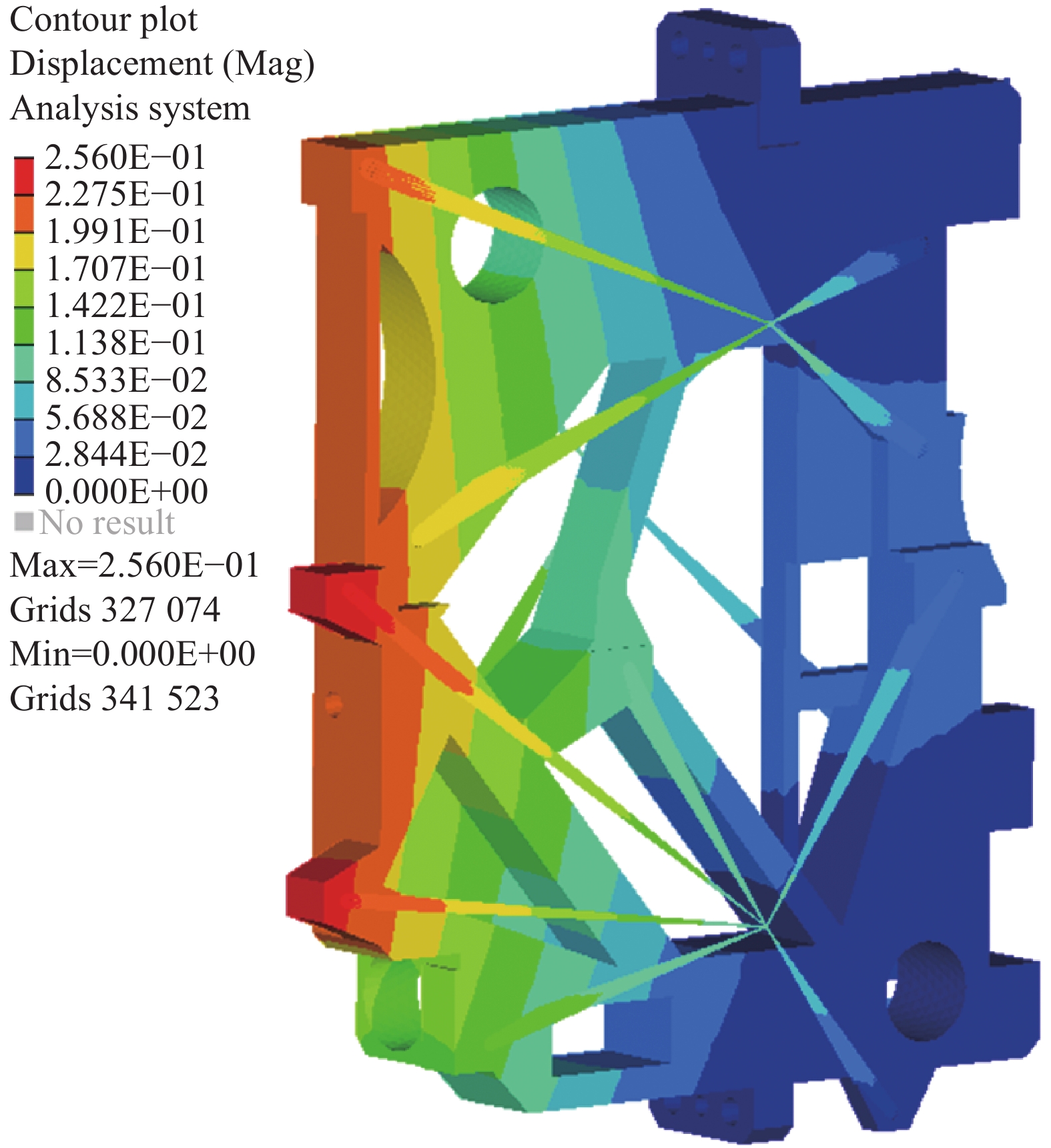
对图7(b)中光具座组件开展过载分析,分别对X、Y、Z三向40 g过载工况进行分析。分析得到光具座在三向过载下的最大位移分别为0.017、0.015、0.256 mm,三向过载下的柔顺度分别为10.2、9.47、100.29 N·mm。优化后光具座结构在Z向过载下的位移云图如图9所示。

图 9 优化重构后光具座组件Z向过载下的位移云图
Figure 9. Deformation charts of optimized reconstructed optical bench component under acceleration conditions in Z direction
对光具座经验设计方案和拓扑优化设计方案的仿真分析结果进行对比,如表1所示。表1中,f2和f3分别表示光具座组件的第二阶模态频率和第三阶模态频率,Uxmax、Uymax和Uzmax分别表示光具座组件在X、Y、Z三向40 g过载工况下的最大位移结果值。
对表1中结果进行分析可见,相比经验设计方案,优化后的光具座结构在质量、频率以及柔顺度等大部分性能方面具有良好的优化效果。优化后,光具座的第三阶模态频率有所下降,但是第三阶模态频率的绝对频率值较高,对巡飞弹载光电控制系统设计几乎无影响,并且不会与外部振动源形成共振,因此该设计结果性能提升明显,可据此开展实物研制。目前,该优化后的光具座结构已经完成加工装配,并随光电系统进行了试验验证,使用效果良好,充分验证了该拓扑优化设计方法的有效性和实用性。此外,该拓扑优化方案也可根据设计需求,应用至巡飞弹载光电其他零件的轻量化设计,具有良好的推广性。
表 1 光具座经验设计方案和拓扑优化设计方案对比
Table 1. Comparison of experience design and topology optimized design for optical bench
Experience
designOptimized
designPerformance
improvementMass/kg 2.57 1.995 +22.4% f1/Hz 149.7 154.3 +3.07% f2/Hz 279.4 290.9 +4.12% f3/Hz 334.3 298.1 −10.83% Cx/N·mm 13.83 10.2 +26.25% Uxmax/mm 0.024 0.017 +29.17% Cy/N·mm 10.89 9.47 +13.04% Uymax/mm 0.019 0.015 +21.05% Cz/N·mm 129.36 100.29 +22.47% Uzmax/mm 0.325 0.256 +21.23% -
为实现巡飞弹载光电关键结构的高效力学承载设计,文中建立了一种基于拓扑优化的巡飞弹载光电关键结构轻量化设计方法。文中提出的轻量化设计方法以结构有限元模型的单元密度为变量,以低阶模态频率和三向过载工况下的结构柔顺度为约束,以质量最小为优化设计目标建立拓扑优化设计模型。通过对该拓扑优化问题进行求解得到结构拓扑布局方案,进而根据优化结果开展几何重构工作,并对各项性能指标进行再次分析校核。文中利用该方法对某巡飞弹载光电关键结构光具座进行了优化设计,相比经验设计方案,拓扑优化设计方案质量降低22.4%,同时各项力学性能均满足系统设计要求。该优化设计方案已在实际产品中得到了应用验证,取得了良好的使用效果。文中工作成功将拓扑优化方法拓展应用于新型巡飞弹载光电系统关键结构的设计,可显著提高巡飞弹载光电结构的轻量化设计水平。
Topology optimization method for key structures of electro-optic systems of loitering munition
-
摘要: 伴随巡飞弹这一新型武器系统的快速发展,巡飞弹载光电载荷设计过程中关于小型化、轻量化、抗过载等多种要求的设计矛盾日益突出。为解决巡飞弹载光电系统小型化轻量化前提下的高效承载问题,建立了一种基于拓扑优化的巡飞弹载光电关键结构设计方法。该方法以结构低阶模态频率和过载工况下的结构柔顺度为设计约束,以质量最小为目标,建立了基于变密度法的拓扑优化设计模型,进而利用Altair HyperWorks软件求解得到关键结构的拓扑布局方案,之后综合弹载光电系统功能要求和零件加工工艺等要求,利用UG软件对拓扑优化结果进行几何模型重构并开展校核分析,最终完成关键结构的优化设计方案。在应用算例中,首先对某巡飞弹载光电关键结构零件光具座的经验设计方案进行了分析,然后利用该拓扑优化设计方法,在主要力学性能保持不变甚至部分性能有所提升的前提下,将该光具座结构成功减重22.4%,有效提高了该巡飞弹载光电系统的轻量化水平和结构承载效能,满足了系统设计要求,同时也表明了该优化设计方法的有效性和实用性,具有良好的推广性。Abstract:
Objective The electro-optic system is an important component of loitering munition. With the rapid development of loitering munition in recent years, the electro-optic systems of loitering munition are expected to be more compact, light, and with more excellent performance. Therefore, advanced design methods are urgently needed to solve the above problems in the electro-optic system design. In order to meet the multiple requirements of loitering munition, an effective design method for key structures of electro-optic systems based on topology optimization was proposed. Methods The advanced topology optimization method was employed to raise the design standard of electro-optic systems. Specifically, the stiffness under acceleration conditions in X, Y, Z directions and the first modal frequency were all considered as the optimization design constraints, and mass minimization of the design structure of electro-optic systems of loitering munition was taken as the optimization objective function in the proposed topology optimization method. The variable density method was employed to establish the topology optimization model. The optimized topology layout of the electro-optic systems structure can be obtained by solving the topology optimization model with the help of Altair HyperWorks software, then it would be used to reconstruct the geometric models based on production technology with the software of Unigraphics NX. In the next step, the reconstruction model would be analyzed to confirm if the optimized design could meet all the requirements. Results and Discussions As the key structure of electro-optic systems of the loitering munition, the optical bench was analyzed and optimized to improve the design performance using the proposed method. In this typical example, the topology optimized result of optical bench was obtained (Fig.5) and reconstructed (Fig.7). Then the modal analysis (Fig.8) and overload analysis (Fig.9) were executed to verify the performance of optimized reconstructed optical bench. The result showed that the mass of optical bench of electro-optic systems was reduced by 22.4% with stiffness under acceleration conditions in X, Y, Z directions and the first modal frequency maintaining equivalent performances (Tab.1). In the completed example, the optimization method has greatly improved the lightweight level of electro-optic systems of loitering munition, and it offers great help in meeting the requirements of loitering munition system. In especial, the optimized design of optical bench has been produced and successfully applied to the electro-optic systems. Obviously, the proposed method can also be extended to the design of other parts to improve the overall design level. Conclusions In this study, an effective design method for key structures of electro-optic systems based on topology optimization is proposed. The mass, stiffness and the first modal frequency of the key structure are all considered in the optimization design method to ensure design effectiveness. As a typical example, the optical bench was analyzed, optimized, reconstructed and checked successively during the whole design flow and the optimized design of optical bench has also been produced and verified in the physical test. Compared to experiential design, the topology optimized optical bench has a significant advantage in weight and stiffness. The result of the example showed that the proposed topology optimization method can effectively benefit the lightweight design of the electro-optic systems of loitering munition. Therefore, the topology optimization method for key structures of electro-optic systems of loitering munition has great appliance and good popularization value. -
Key words:
- topology optimization /
- loitering munition /
- electro-optic systems /
- optical bench
-
图 1 巡飞弹载光电载荷组成示意图
Figure 1. Schematic diagram of electro-optic systems for loitering munition
图 2 光具座组件有限元模型:(a)视角1;(b)视角2
Figure 2. Finite element model of optical bench component: (a) View 1; (b) View 2
图 4 光具座拓扑优化结果单元密度示意图
Figure 4. Schematic diagram of topology optimized result for optical bench with element density
图 5 光具座拓扑优化结果示意图
Figure 5. Schematic diagram of topology optimized result of optical bench
图 6 (a) 光具座质量的优化收敛曲线;(b)光具座组件一阶频率优化收敛曲线;(c)光具座组件柔顺度优化收敛曲线
Figure 6. (a) Optimized convergence curve of the optical bench mass; (b) Optimized convergence curve of f1 of optical bench component; (c) Optimized convergence of Cx, Cy, Cz of optical bench component
图 7 (a)光具座重构结构几何模型;(b)光具座重构结构有限元模型
Figure 7. (a) Geometric model of reconstructed optical bench; (b) Finite element model of reconstructed optical bench
图 8 优化重构后光具座组件一阶振型图
Figure 8. The first modal shape of optimized reconstructed optical bench component
图 9 优化重构后光具座组件Z向过载下的位移云图
Figure 9. Deformation charts of optimized reconstructed optical bench component under acceleration conditions in Z direction
表 1 光具座经验设计方案和拓扑优化设计方案对比
Table 1. Comparison of experience design and topology optimized design for optical bench
Experience
designOptimized
designPerformance
improvementMass/kg 2.57 1.995 +22.4% f1/Hz 149.7 154.3 +3.07% f2/Hz 279.4 290.9 +4.12% f3/Hz 334.3 298.1 −10.83% Cx/N·mm 13.83 10.2 +26.25% Uxmax/mm 0.024 0.017 +29.17% Cy/N·mm 10.89 9.47 +13.04% Uymax/mm 0.019 0.015 +21.05% Cz/N·mm 129.36 100.29 +22.47% Uzmax/mm 0.325 0.256 +21.23%  下载: 导出CSV
-
[1] Li Yongtao, Lv Xinmeng, Wu Fengling. Construction of optic-electronic countermeasure testing environment of loitering missile testing [J]. Electro-Optic Technology Application, 2022, 37(2): 74-78. (in Chinese) [2] Li Huaitao. Research on seeker, guidance and control technology for loitering munition[D]. Beijing: Beijing Institute of Technology, 2016. (in Chinese) [3] Bendsøe M P, Kikuchi N. Generating optimal topologies in structural design using a Homogenization Method [J]. Computer Methods in Applied Mechanics and Engineering, 1988, 71(2): 197-224. doi: 10.1016/0045-7825(88)90086-2 [4] Zhu J H, Zhang W H, Beckers P, et al. Simultaneous design of components layout and supporting structures using coupled shape and topology optimization technique [J]. Structural and Multidisciplinary Optimization, 2008, 36(1): 29-41. doi: 10.1007/s00158-007-0155-x [5] Yang Chenxi, Yu Shengqiang, Yan Hongsong, et al. Research on topology optimization method of INS structure [J]. Navigation Positioning & Timing, 2021, 8(4): 149-157. (in Chinese) [6] Chen Hongfang, Han Mengrui, Sun Ruoshui, et al. Methods for topology optimization of lightweight mechanical structures in laser tracking systems [J]. Journal of Harbin Engineering University, 2022, 43(2): 282-289. (in Chinese) [7] Wang Ruixian, Feng Zhenwei, Ma Lingxi, et al. Topology optimization of sensor brackets for small satellites [J]. Journal of Nanjing University of Aeronautics & Astronautics, 2021, 53: 67-70. (in Chinese) [8] Zhu Jihong, Wei Chang, Hou Jie, et al. A topology optimization method for shape memory alloy structures [J]. Chinese Journal of Computational Mechanics, 2021, 38(4): 452-461. (in Chinese) [9] Ma Jing, Kang Zhan. An additional gravity field method for topology optimization of cast parts [J]. Chinese Journal of Computational Mechanics, 2021, 38(4): 498-504. (in Chinese) [10] Li Yuan, Jiao Mingyin, Chang Weijun, et al. Lightweight topological optimization design of scanning mirror [J]. Infrared and Laser Engineering, 2011, 40(7): 1294-1298. (in Chinese) [11] Liu Zhongyu, Zhang Tao, Wang Ping, et al. Topology optimization design for main frame of infrared seeker's stabilization platform [J]. Infrared and Laser Engineering, 2016, 45(2): 0218001. (in Chinese) doi: 10.3788/irla201645.0218001 [12] Yang Xue. Topology optimization design and vibration simulation of seeker based a variable density method [J]. Environmental Technology, 2021: 18-31. (in Chinese) [13] Wang Shang, Zhang Xingxiang, Sha Wei, et al. Topology optimization design and analysis of an integrated aluminum alloy mirror [J]. Infrared Technology, 2022, 44(1): 61-65. (in Chinese) [14] Wang Jing, Ji Ming, Zhang Chong, et al. Simulation on influence factor of line of sighting stabilization precision [J]. Command Control & Simulation, 2013, 35(6): 86-91. (in Chinese) [15] Stolpe M, Svanberg K. An alternative interpolation scheme for minimum compliance topology optimization [J]. Structural and Multidisciplinary Optimization, 2001, 22(2): 116-124. doi: 10.1007/s001580100129 -

 点击查看大图

计量
- 文章访问数: 136
- HTML全文浏览量: 26
- PDF下载量: 31
- 被引次数: 0


