


-
近年来,随着红外成像技术的发展[1-3],红外折射式镜头由于具有视场大、体积小、成本低等特点,在航天遥感、军事侦查、生物探测等领域得以广泛应用,对系统成像性能提出了更高要求[4-6]。
目前,国内外红外折射式镜头的高精度装调主要采用精密定心的方式[7-9],依据定心仪测量光学件像点随回转轴旋转的轨迹,计算和调整光学件的中心偏。然而,常用的红外折射材料主要有锗、硅、硒化锌和硫系玻璃等,由于材料制备工艺特点,折射率均匀性难以保证[8-11],如锗材料在10.6 μm谱段折射率均匀性约为2×10⁻⁴,硫系玻璃在3.39 μm谱段折射率均匀性约为1×10⁻⁴。相较于可见折射材料10−6量级的折射率均匀性,红外材料折射率均匀性的高偏差相当于在成像系统中引入额外的不规则像差,将导致镜头波前误差异常和像质下降,这是高性能红外折射式镜头装调的主要难题,而精密定心装调的核心是光学件光轴一致性和间距的控制,对系统不规则像差的矫正无能为力。
针对上述难题,文中提出面向高性能的红外折射式镜头装调技术,设计了在线装调检测装置,依据镜头实测波前,通过迭代调整光学件位置的方法矫正系统波前初阶像差,对残留的中高阶像差采用修配光瞳处光学件面形,引入反残留波像差的方式补偿。借助于该技术完成红外镜头装调工作,相较于精密定心后的镜头测量结果,系统波前补偿效果明显,镜头成像性能大幅提升,验证了该技术的合理性。
-
用于红外折射式镜头的光学件材料主要有锗、硅、硒化锌和硫系玻璃等,多采用晶体生长的方式制备[10-12],材料在生长过程中受温度或压力等因素波动的影响,会导致不同区域晶格生长残余应力水平不同,引起材料各区域的折射率存在一定偏差。
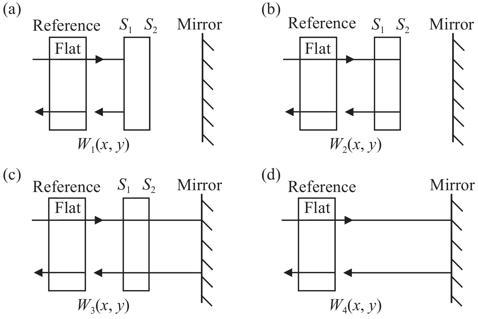
在光学上采用四步干涉法测量光学材料的折射率均匀性[13-15],如图1所示,通过测试待测材料平面样品的前后表面反射波前、透射波前和测试光路空腔波前的误差分布,由公式(1)求得该样品的折射率均匀性偏差分布Δn(x, y):
$$ \Delta n\left( {x,y} \right) = \frac{{n({W_3} - {W_4}) - (n - 1)({W_2} - {W_1})}}{{2t}} $$ (1) 式中:t为样品的平均厚度;n为样品在测试波长的折射率;W1为样品前表面S1反射的波前误差分布;W2为经样品透射,后表面S2反射的波前误差分布;W3为经样品透射,由标准平面镜反射的波前误差分布;W4为移出样品后,仅由标准平面镜反射的测试光路空腔波前误差分布。

图 1 (a) 样品前表面S1反射波前;(b) 样品后表面S2反射波前;(c) 样品透射波前;(d) 测试光路空腔波前
Figure 1. (a) Reflected wavefront of sample’s front surface S1; (b) Reflected wavefront of sample’s back surface S2; (c) Transmitted wavefront of sample; (d) Cavity wavefront of test optical path
使用3.39 μm红外干涉仪对国内部分材料制备商提供的口径Φ200 mm红外折射材料样品测量折射率均匀性,结果如图2所示,样品硅和硒化锌的折射率均匀性偏差小且分布比较均匀,但样品锗和硫化锌的折射率均匀性偏差大且呈不规则分布。

图 2 (a) 样品硅、(b) 样品硒化锌、(c) 样品锗、(d) 样品硫化锌的折射率均匀性分布
Figure 2. Refractive index homogeneity of sample Si (a), sample ZnSe (b), sample Ge (c), sample ZnS (d)
由于红外光学材料折射率均匀性的高偏差相当于在光学系统波前附于一个不规则的曲面波,将在系统引入难以评估的初阶和高阶像差,按设计值装调的红外镜头势必会产生波前误差异常和像质下降的问题。
-
按照计算机辅助装调技术理论[16],理想光学系统的综合像差与各光学件位置结构参数之间的函数关系可用近似线性方程组(2)表示:
$$ \left[\begin{array}{c} F_{1} \\ \vdots \\ F_{m} \end{array}\right]=\left[\begin{array}{c} F_{01} \\ \vdots \\ F_{0 m} \end{array}\right]+\left[\begin{array}{c} \dfrac{\delta f_{1}}{\delta x_{1}}\left(x_{1}-x_{01}\right)+\cdots+\dfrac{\delta f_{1}}{\delta x_{n}}\left(x_{n}-x_{0 n}\right) \\ \vdots \\ \dfrac{\delta f_{m}}{\delta x_{1}}\left(x_{1}-x_{01}\right)+\cdots+\dfrac{\delta f_{m}}{\delta x_{n}}\left(x_{n}-x_{0 n}\right) \end{array}\right] $$ (2) 式中:Fi和F0i (i=1, 2, ··· , m)分别为系统实测和设计残留的各阶像差;fi (i=1, 2, ··· , m)为系统像差与各光学件位置关系的函数;xj和x0j (j=1, 2, ··· , n) 分别为各光学件实际和设计位置参数。
用矩阵来表示,公式(2)可写为:
$$ \Delta F=A \Delta X $$ (3) 其中
$$ \Delta F=\left[\begin{array}{c} F_{1} \\ \vdots \\ F_{m} \end{array}\right]-\left[\begin{array}{c} F_{{0n}} \\ \vdots \\ F_{{0m}} \end{array}\right]$$ $$ A=\left[\begin{array}{c} \dfrac{\delta f_{1}}{\delta x_{1}}, \cdots, \dfrac{\delta f_{1}}{\delta x_{n}} \\ \vdots \\ \dfrac{\delta f_{m}}{\delta x_{1}}, \cdots, \dfrac{\delta f_{m}}{\delta x_{n}} \end{array}\right]$$ $$ \Delta X=\left[\begin{array}{c} x_{1} \\ \vdots \\ x_{n} \end{array}\right]-\left[\begin{array}{c} x_{01} \\ \vdots \\ x_{0 n} \end{array}\right] $$ 式中:A为系统中各光学件的灵敏度矩阵,由光学设计数据确定,主要对系统初阶像差敏感;ΔX为系统中各光学件所需的位置调整量,包括平移、倾斜和间距;ΔF为系统实测和理论像差的偏差值。
对于折射式系统,每件光学件均有五个维度位置调整量,在只考虑五项初阶像差的情况下,像差数m远小于调整量总数n,不定方程式(3)多为无穷多组解。为了保证光学件调整后对系统参数和结构影响最小,取评价函数ψ (ΔX),其极小值就是公式(3)的解。
$$ \varPsi(\Delta X)=\Delta X^{{\rm{T}}} \Delta X=\sum_{i=1}^{n}\left(x_{i}-x_{0 i}\right)^{2} $$ (4) 根据实测光学系统的残留像差,通过光学件的位置补偿调整,可减小光学系统的初阶像差,使调整后的光学系统指标尽可能接近理论系统。但红外光学材料折射率均匀性的高偏差使得镜头按光学设计值精密定心后,系统波前残留大量级的不规则像差,并且与调整量存在非线性关系,因此只能通过调整量ΔX迭代的方式收敛残留初阶像差。
-
为了实现红外折射式镜头的残留初阶像差最优化处理,需将镜头装调和检测相统一,在镜头精密定心装调后,实时监测系统波前,并依据实测初阶像差在线迭代调整光学件位置。
为此,基于红外折射式镜头精密定心的基础上,通过在定心仪精密转台安置一个45°折转镜,配合镜头支撑工装,将镜头垂直光轴转换至水平方向,如图3所示。在镜头入瞳上方安装可调整角度的平面反射镜,通过工况切换装置的旋进和旋出,实现镜头检测和装调工况的任意切换,并结合红外干涉仪,使红外折射式镜头装调过程中具备系统波前检测的功能。

图 3 在线装调检测平台模型图
Figure 3. Model diagram of online device with lens alignment and image quality measurement
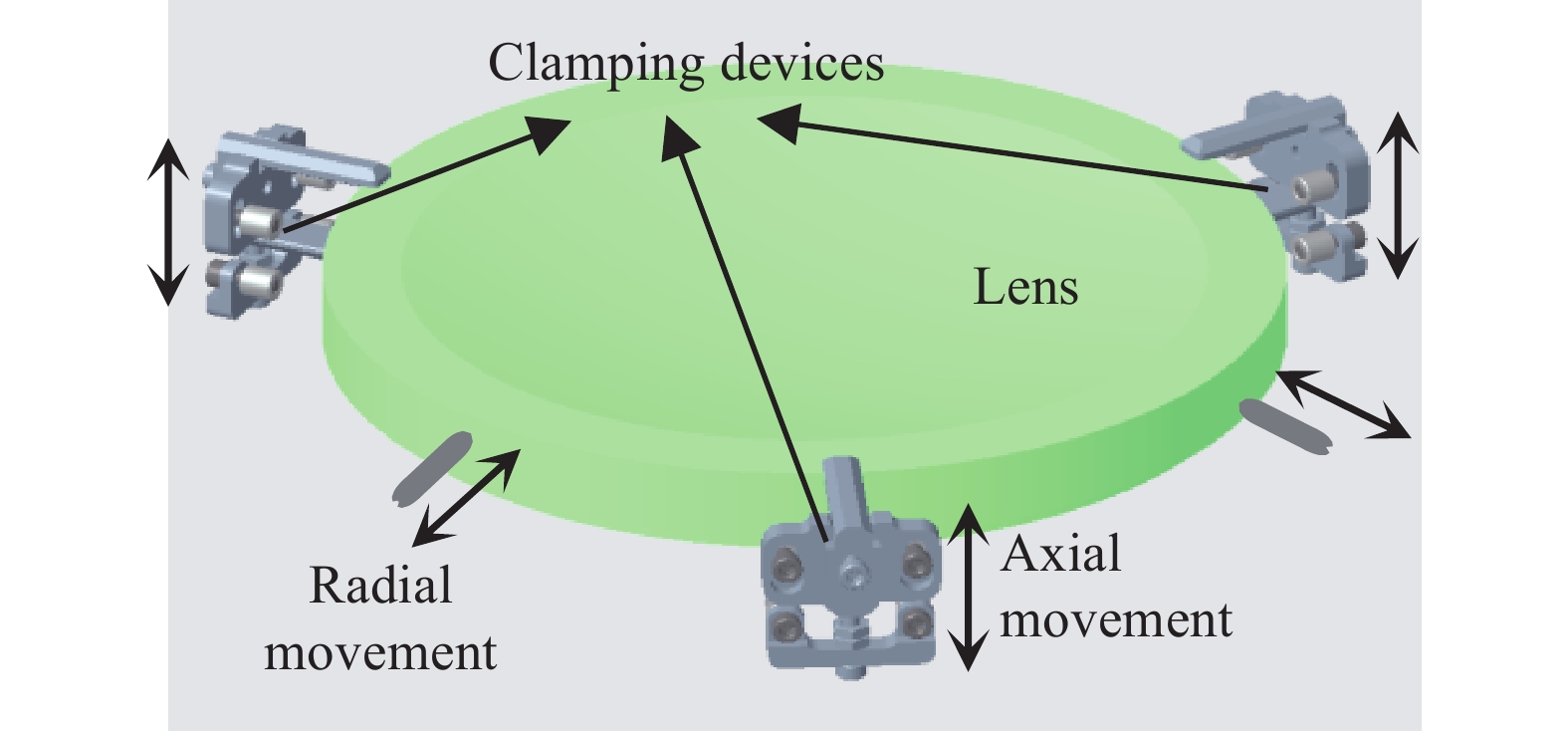
在线迭代调整的关键是光学件在镜筒内可实时进行倾斜、平移和间距的调整,原理如图4所示,采用在镜筒侧壁均布的三个夹持装置支撑光学件,通过对光学件端面三个支撑点的轴向组合升降,并结合镜筒侧壁顶丝的径向协调伸缩,实现光学件在镜筒内的五维自由度调整。

图 4 位置迭代调整原理图
Figure 4. Schematic diagram of iterative adjustment position
-
理想成像光学系统的出射波前应为完善球面波,当系统具有像差时,系统出射波前将产生形变,实际波面与理想波面存在波像差,如图5所示。

图 5 像差对系统波前影响示意图
Figure 5. Schematic diagram of aberration effect on system wavefront
光学系统中残留的中高阶像差通常与光学件的位置失调关系不大,主要与光学件面形和参数加工精度及材料特性相关。按照波面的补偿原理[17],可通过光学件面形的变形加工在系统中引入反残留波像差的补偿波面,将出射波前校正成完善球面波,如图6所示。

图 6 系统波前补偿示意图
Figure 6. Schematic diagram of system wavefront compensation
光学系统波像差和光学件面形像差的分布均可通过极坐标形式的Zernike多项式表征。由干涉测量得到如公式(5)所示的光学系统波像差分布W(ρ, θ),结合光学设计数据确定的变形镜面形对系统出射波前的波像差响应矩阵C,由公式(6)计算得到变形镜面形像差分布W´(ρ, θ)。
$$ \left\{\begin{array}{l} W(\rho, \theta)= \displaystyle \sum_{j=1}^{L} k_{j} Z_{j}(\rho, \theta)=K Z \\ K=\left[k_{1}, k_{2}, \cdots, k_{L}\right] ; Z=\left[Z_{1}, Z_{2}, \cdots, Z_{L}\right]^{{\rm{T}}} \end{array}\right. $$ (5) 式中:Zj和kj (j=1, 2,
$\cdots , $ L)分别为各项Zernike多项式及其对应项系数;L为项数。$$ \left\{\begin{array}{c} W^{\prime}(\rho, \theta)=-C^{-1} K Z \\ C=\left[\begin{array}{c} c_{11}, c_{12}, \cdots, c_{1 L} \\ \vdots \\ c_{L 1}, c_{L 2}, \cdots, c_{L L} \end{array}\right] \end{array}\right. $$ (6) 式中:cij (i, j=1, 2,
$\cdots , $ L)表示变形镜的第j项Zernike面形像差对出射波前的第i项Zernike波像差的影响。为了降低变形镜面形修配难度和提高补偿波面匹配度,系统波前的初阶像差采用光学件位置调整的方法矫正,仅对残留的中高阶像差进行面形修配补偿波前。一般而言,在折射式镜头光瞳处全口径使用的光学件面形对全视场系统波像差影响最为均衡,为了保证补偿波面对全视场中高阶像差矫正效果,同时降低面形修配难度,将反残留波像差通过公式(6)等效在光瞳处光学件的表面附加变形面形,并严格按照面形的像差分布进行面形修配。
-
折射式镜头通常具有视场角大的特点,由于材料折射率均匀性的高偏差,不同视场的系统残留波像差因入射光线路径不同而产生一定相对不规则差异,无法得到一个可全视场完善补偿的波面。
为了使镜头各视场系统波前的中高阶像差均得到有效改善,需综合分析多视场的波像差分布情况,通过公式(7)利用Zernike多项式计算拟合得到最优化的反残留波像差分布Wf (ρ, θ),即变形镜在轴上视场的补偿波像差。
$$ W_{f}(\rho, \theta)=\frac{ \displaystyle \sum_{i=1}^{N} b_{l} W_{l}(\rho, \theta)}{N} $$ (7) 式中:Wl (ρ,θ) (l=1, 2,
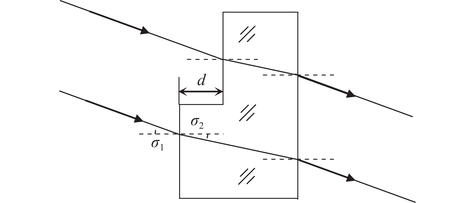
$ \cdots , $ N)为镜头各视场实测系统波前;bl (l=1, 2,$ \cdots , $ N)为各视场波前的影响系数;N为分析视场个数,通常不小于3。影响系数bl与变形镜面形对相应视场系统波像差的影响互为倒数。根据波像差与入射角的关系,如图7所示,可知光学件面形对波像差的影响随入射光角度的增大而减小,见公式(8):
$$ \left\{\begin{array}{l} S=\left(\dfrac{n}{\cos \sigma_{2}}-\dfrac{1}{\cos \sigma_{1}}\right) d \\ \sin \sigma_{1}=n \sin \sigma_{2} \end{array}\right. $$ (8) 式中:S为折射波像差;n为光学件在测试波长的折射率;σ1和σ2分别为入射光和出射光与镜面法线夹角;d为镜面面形法向偏差量。

图 7 波像差与入射角关系示意图
Figure 7. Schematic diagram of the relationship between wave aberration and incident angle
定义镜头0°视场角的波前影响系数为1,基于公式(8)得到各视场波前的影响系数。
$$ b_{l}=\dfrac{\left(n^{\prime}-1\right) \cos \alpha_{l}\, \cos\, \arcsin \left(\dfrac{\sin \alpha_{l}}{n^{\prime}}\right)}{n^{\prime} \cos \alpha_{l}-\arccos \,\arcsin \left(\dfrac{\sin \alpha_{l}}{n^{\prime}}\right)} $$ (9) 式中:n'为变形镜在测试波长的折射率;αl (l=1, 2,
$ \cdots , $ N)为镜头实测波前对应的视场角。 -
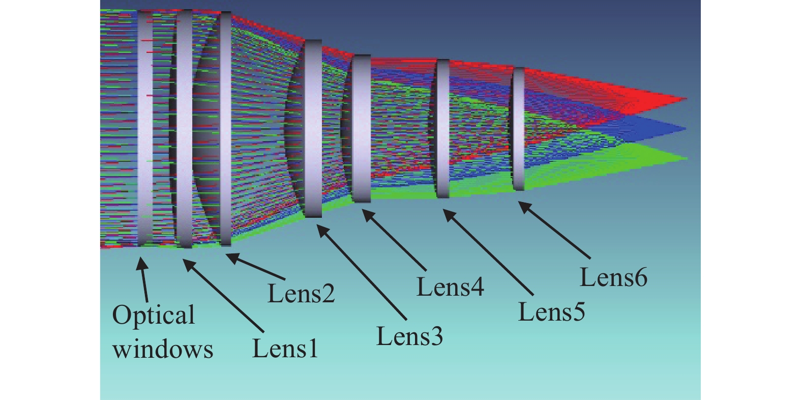
为了验证系统波前补偿效果,采用该技术对某全视场角13°的中波红外折射式镜头进行装调,镜头的光学结构如图8所示,共由一块窗口和六块透镜组成,其中窗口前表面为系统光瞳,镜头全视场MTF (@25 lp/mm)设计值为0.70,光学系统部分参数如表1所示。

图 8 红外镜头的光学结构图
Figure 8. Optical structure diagram of infrared lens
表 1 红外镜头光学系统部分参数
Table 1. Some optical system parameters of infrared lens
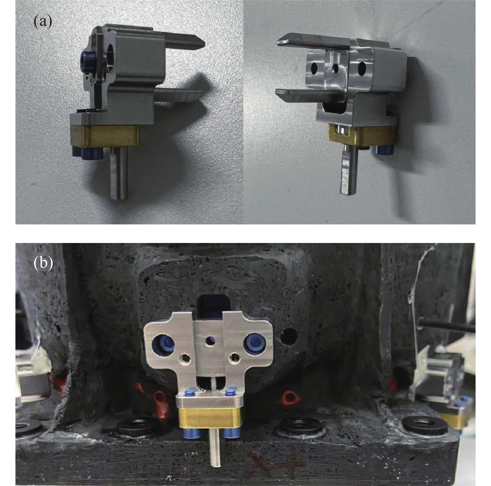
Element Material Thickness/mm Aperture/mm Optical windows CaF2 13.002 205 Lens1 Si 15.033 210 Lens2 Si 15.950 205 Lens3 Ge 13.081 160 Lens4 Ge 11.367 135 Lens5 Si 11.616 130 Lens6 ZnSe 9.612 120 镜头装调采用精密定心的方式,为了便于光学件在线迭代调整,在镜筒侧壁预留了夹持装置安装位。基于红外定心仪和红外干涉仪构建了在线装调检测平台,其中夹持装置的调整精度为±5 μm,其结构形式和与镜筒连接方式如图9所示。

图 9 (a) 夹持装置的结构形式;(b) 夹持装置与镜筒的连接方式
Figure 9. (a) Structure of clamping device; (b) Connection mode between clamping device and lens barrel
镜头严格按照光学设计公差进行装调后,将平面反射镜旋进光路,使用3.39 μm红外干涉仪在线进行镜头三个视场的系统波前和MTF(@25 lp/mm)测试,像差分布采用36项Zernike系数拟合,测试结果见表2。因红外材料折射率均匀性的高偏差导致各视场系统波前均呈三叶草形状分布,残留有较大的各阶像差,三个视场的平均MTF(@25 lp/mm)仅为0.31,远低于设计值。
表 2 镜头精密定心后的像质测试结果
Table 2. Measurement results of lens image quality after precision centering
FOV System wavefront
diagram & MTF
(λ=3.39 μm)Zernike coefficients of
main aberration terms+6.5° 
First order: k5: −0.074;
k6: −0.055; k7: 0.202;
k8: 0.024; k9: 0.167.
Medium & high order:
k10: −0.044; k11: −0.027;
k12: 0.159; k14: 0.020;
k16: −0.133; k19: 0.091;
k20: 0.066; k30: −0.047.0° 
First order: k5: −0.030;
k6: −0.009; k7: −0.089;
k8: −0.037; k9: 0.149.
Medium & high order:
k10: −0.057; k11: −0.037;
k12: 0.095; k14: 0.030;
k16: −0.128; k19:0.111;
k20: 0.089; k30: −0.047.−6.5° 
First order: k5: 0.050;
k6: −0.062; k7: −0.326;
k8: −0.041; k9: 0.127.
Medium & high order:
k10: −0.168; k11: −0.057;
k12: 0.084; k14: 0.058;
k16: −0.116; k19: 0.062;
k20: 0.084; k30: −0.046.基于镜1~6的灵敏度矩阵,针对三个视场系统波前初阶像差进行矫正。经光学件位置迭代调整补偿方法计算出,通过镜2轴向移动和镜4径向平移的组合调整,可快速且最优化矫正系统波前初阶像差。在装调检测平台上根据系统实测波前,利用夹持装置和镜筒侧壁顶丝实时迭代调整镜2轴向移动和镜4径向平移,直至各项初阶像差达到最小值。调整后镜头系统波前和MTF(@25 lp/mm)测试结果见表3,三个视场的系统波前初阶像差基本矫正,残留的中高阶像差基本无变化,各视场平均MTF(@25 lp/mm)提升至0.46。
表 3 镜头迭代调整后的像质测试结果
Table 3. Measurement results of lens image quality after iterative adjustment position
FOV System wavefront
diagram & MTF
(λ=3.39 μm)Zernike coefficients of
main aberration terms+6.5° 
First order: k5: 0.010;
k6: 0.007; k7: 0.011;
k8: 0.023; k9: 0.029.
Medium & high order:
k10: 0.015; k11: −0.031;
k12: 0.133; k14: 0.032;
k16: −0.125; k19: 0.078;
k20: 0.073; k30: −0.050.0° 
First order: k5: −0.011;
k6: 0.009; k7: −0.032;
k8: 0.020; k9: 0.007.
Medium & high order:
k10: −0.069; k11: −0.058;
k12: 0.078; k14: 0.012;
k16: −0.118; k19:0.100;
k20: 0.084; k30: −0.044.−6.5° 
First order: k5: 0.015;
k6: −0.013; k7: −0.015;
k8: 0.022; k9: 0.001.
Medium & high order:
k10: −0.155; k11: −0.046;
k12: 0.055; k14: 0.075;
k16: −0.118; k19: 0.090;
k20: 0.091; k30: −0.041.对于镜头三个视场残留的中高阶像差,按照面形修配补偿波前的方法计算反残留波像差,并等效在系统光瞳处窗口前表面进行面形修配。修配后窗口的透射波前测试结果见表4。
表 4 修配后窗口的透射波前测试结果
Table 4. Transmission wavefront measurement result of the repaired optical windows
FOV Transmission wavefront
(λ=3.39 μm)Zernike coefficients of medium &
high order aberration terms0° 
k10: 0.064; k11: 0.031;
k12: −0.080; k14: −0.044;
k16: 0.118; k19:- 0.099;
k20: −0.073; k30: 0.051.将修配后窗口按波前补偿匹配方位安装到镜筒中,镜头三个视场的系统波前和MTF(@25 lp/mm)测试结果见表5,各视场各阶像差得到有效补偿,平均MTF(@25 lp/mm)提升至0.67,基本接近设计值。系统波前补偿完成后,从镜筒侧壁注胶孔对各光学件径向注胶,待胶斑固化,将夹持装置从镜筒拆下,使光学件处于悬浮胶粘状态,镜头装调完成。
表 5 镜头面形修配后的像质测试结果
Table 5. Measurement results of lens image quality after surface modification
FOV System wavefront
diagram & MTF
(λ=3.39 μm)Zernike coefficients of
main aberration terms+6.5° 
First order: k5: 0.011;
k6: 0.005; k7: 0.015;
k8: 0.019; k9: 0.017.
Medium & high order:
k10: 0.072; k11: 0.004;
k12: 0.087; k14: −0.007;
k16: −0.010; k19: −0.025;
k20: −0.015; k30: −0.007.0° 
First order: k5: −0.009;
k6: 0.014; k7: −0.021;
k8: 0.018; k9: 0.005.
Medium & high order:
k10: −0.007; k11: −0.023;
k12: −0.005; k14: −0.030;
k16: −0.006; k19:0.007;
k20: 0.009; k30: 0.004.−6.5° 
First order: k5: 0.012;
k6: −0.015; k7: −0.017;
k8: 0.015; k9: 0.002.
Medium & high order:
k10: −0.095; k11: −0.019;
k12: −0.029; k14: 0.035;
k16: −0.007; k19: −0.007;
k20: 0.027; k30: 0.006. -
由于红外材料折射率均匀性的高偏差,使得高性能的红外折射式镜头装调十分困难。文中在精密定心装调的基础上,提出了一种面向高性能的红外折射式镜头装调技术。通过在线检测装置和夹持装置的引入,将镜头装调和检测相融合,并以系统灵敏度矩阵为依据,实时迭代调整光学件位置矫正初阶像差。同时对系统残留的中高阶像差,采用修配光瞳处光学件面形,引入反残留波像差的方式补偿。实验结果表明,该技术可大幅提升红外折射式镜头成像性能,打破传统折射式镜头装调方法的局限,为高性能红外系统研制提供了一种可行途径。
Alignment technology for infrared refractive lens based on high performance
-
摘要: 针对红外光学材料折射率不均匀导致系统波前产生异常像差,从而引起镜头像质严重下降的问题,提出了一种光学件位置迭代调整和面形修配相结合的系统波前补偿方法,实现面向高性能的红外折射式镜头装调。在光学件精密定心的基础上,设计了在线装调检测装置,依据镜头实测波前并结合计算机辅助装调技术,通过迭代调整光学件位置矫正系统波前初阶像差。对系统残留的中高阶像差,根据各视场测得的系统波前综合分析计算,采用修配光瞳处光学件面形,引入反残留波像差的方式补偿。实验上,通过对某红外折射式镜头装调,将镜头三个视场系统波前RMS (λ=3.39 μm)分别由精密定心后的0.162λ、0.118λ、0.166λ降低至0.064λ、0.040λ、0.067λ,平均MTF (@25 lp/mm)由0.31提升至0.67。结果表明,这种装调技术对红外折射式镜头系统波前补偿效果明显,可大幅提升镜头成像性能,具有重要的工程应用价值。Abstract:
Objective Due to the characteristics of large field of view, small size and low cost, infrared refractive lenses have been widely used in aerospace remote sensing, military reconnaissance, biological detection and other fields. With the development of infrared imaging technology, higher requirements are put forward for the technical specifications of imaging systems. Therefore, improving the imaging performance of lenses becomes the key in the alignment process. At present, the high-precision alignment of infrared refractive lenses at home and abroad mainly adopts the method of centering error measurement, which makes the centering error of each optical element within the tolerance range by adjusting its position. However, due to the preparation process characteristics of infrared optical materials, the refractive index homogeneity of most materials is difficult to guarantee (Fig.2), which must introduce additional irregular aberrations into the optical system, and lead to the degradation of lens imaging performance. The core of precise centering error measurement and alignment is the control of optical axis consistency and spacing of optical elements, which can't do anything to correct the irregular aberrations of the system. For this reason, a system wavefront compensation method combining the iterative adjustment position and the surface modification for the optical elements was presented to realize infrared lenses alignment based on high performance. Methods Based on the precise centering error measurement of lens, an online device with lenses alignment and image quality measurement was designed (Fig.3), which can switch the measurement and alignment conditions through the planar mirror switching device to cut in and out. According to the measured wavefront results of the lens and the computer aided alignment technology, the positions of the optical elements were iteratively adjusted by the clamping devices and jackscrews to correct the first-order aberrations (Fig.4). The residual medium and high-order aberrations of the system were compensated by repairing the optical element surface at the pupil and introducing the anti-residual wave aberrations, on the basis of comprehensive analysis and calculation of system wavefronts measured in several fields of view (Fig.6). Results and Discussions A medium wavelength infrared refractive lens was aligned by means of systematic wavefront compensation. Due to the refractive index inhomogeneity of materials, the RMS (λ=3.39 μm) of the system wavefronts for the lens's three fields of view were 0.162λ, 0.118λ and 0.166λ respectively after precision centering (Tab.2). Based on the sensitivity matrix, the first-order aberrations were corrected by iteratively adjusting the positions of the optical elements, which decreased the RMS (λ=3.39 μm) of the three fields of view to 0.090λ, 0.083λ and 0.098λ (Tab.3). Then, the residual medium and high-order aberrations were compensated by repairing the surface of the optical windows (Tab.4), and the RMS (λ=3.39 μm) of the three fields of view were reduced to 0.064λ, 0.040λ and 0.067λ at last (Tab.5). The results show that this alignment technology can effectively compensate the system wavefronts of the infrared lenses and greatly improve the image performance, which has important engineering application value. Conclusions Due to the high deviation of the refractive index homogeneity of infrared optical materials, it was very difficult to align infrared refractive lenses with high performance. In this study, the alignment technology for infrared refractive lenses based on high performance is proposed. Through the introduction of online device with lenses alignment and image quality measurement, the lens alignment and measurement were integrated, and the positions of the optical elements were iteratively adjusted to correct the first-order aberrations based on the system sensitivity matrix. At the same time, the residual medium and high-order aberrations of the system were compensated by repairing the optical element surface at the pupil and introducing the anti-residual wave aberrations. Through an example of lens alignment, it was verified that this technology can significantly improve the imaging performance of infrared refractive lenses, break through the limitations of traditional methods of lens alignment, and provide a feasible way for developing high performance infrared lens. -
图 1 (a) 样品前表面S1反射波前;(b) 样品后表面S2反射波前;(c) 样品透射波前;(d) 测试光路空腔波前
Figure 1. (a) Reflected wavefront of sample’s front surface S1; (b) Reflected wavefront of sample’s back surface S2; (c) Transmitted wavefront of sample; (d) Cavity wavefront of test optical path
图 2 (a) 样品硅、(b) 样品硒化锌、(c) 样品锗、(d) 样品硫化锌的折射率均匀性分布
Figure 2. Refractive index homogeneity of sample Si (a), sample ZnSe (b), sample Ge (c), sample ZnS (d)
图 3 在线装调检测平台模型图
Figure 3. Model diagram of online device with lens alignment and image quality measurement
图 7 波像差与入射角关系示意图
Figure 7. Schematic diagram of the relationship between wave aberration and incident angle
图 9 (a) 夹持装置的结构形式;(b) 夹持装置与镜筒的连接方式
Figure 9. (a) Structure of clamping device; (b) Connection mode between clamping device and lens barrel
表 1 红外镜头光学系统部分参数
Table 1. Some optical system parameters of infrared lens
Element Material Thickness/mm Aperture/mm Optical windows CaF2 13.002 205 Lens1 Si 15.033 210 Lens2 Si 15.950 205 Lens3 Ge 13.081 160 Lens4 Ge 11.367 135 Lens5 Si 11.616 130 Lens6 ZnSe 9.612 120  下载: 导出CSV
表 2 镜头精密定心后的像质测试结果
Table 2. Measurement results of lens image quality after precision centering
FOV System wavefront
diagram & MTF
(λ=3.39 μm)Zernike coefficients of
main aberration terms+6.5° First order: k5: −0.074;
k6: −0.055; k7: 0.202;
k8: 0.024; k9: 0.167.
Medium & high order:
k10: −0.044; k11: −0.027;
k12: 0.159; k14: 0.020;
k16: −0.133; k19: 0.091;
k20: 0.066; k30: −0.047.0° First order: k5: −0.030;
k6: −0.009; k7: −0.089;
k8: −0.037; k9: 0.149.
Medium & high order:
k10: −0.057; k11: −0.037;
k12: 0.095; k14: 0.030;
k16: −0.128; k19:0.111;
k20: 0.089; k30: −0.047.−6.5° First order: k5: 0.050;
k6: −0.062; k7: −0.326;
k8: −0.041; k9: 0.127.
Medium & high order:
k10: −0.168; k11: −0.057;
k12: 0.084; k14: 0.058;
k16: −0.116; k19: 0.062;
k20: 0.084; k30: −0.046.
下载: 导出CSV
表 3 镜头迭代调整后的像质测试结果
Table 3. Measurement results of lens image quality after iterative adjustment position
FOV System wavefront
diagram & MTF
(λ=3.39 μm)Zernike coefficients of
main aberration terms+6.5° First order: k5: 0.010;
k6: 0.007; k7: 0.011;
k8: 0.023; k9: 0.029.
Medium & high order:
k10: 0.015; k11: −0.031;
k12: 0.133; k14: 0.032;
k16: −0.125; k19: 0.078;
k20: 0.073; k30: −0.050.0° First order: k5: −0.011;
k6: 0.009; k7: −0.032;
k8: 0.020; k9: 0.007.
Medium & high order:
k10: −0.069; k11: −0.058;
k12: 0.078; k14: 0.012;
k16: −0.118; k19:0.100;
k20: 0.084; k30: −0.044.−6.5° First order: k5: 0.015;
k6: −0.013; k7: −0.015;
k8: 0.022; k9: 0.001.
Medium & high order:
k10: −0.155; k11: −0.046;
k12: 0.055; k14: 0.075;
k16: −0.118; k19: 0.090;
k20: 0.091; k30: −0.041.
下载: 导出CSV
表 4 修配后窗口的透射波前测试结果
Table 4. Transmission wavefront measurement result of the repaired optical windows
FOV Transmission wavefront
(λ=3.39 μm)Zernike coefficients of medium &
high order aberration terms0° k10: 0.064; k11: 0.031;
k12: −0.080; k14: −0.044;
k16: 0.118; k19:- 0.099;
k20: −0.073; k30: 0.051.
下载: 导出CSV
表 5 镜头面形修配后的像质测试结果
Table 5. Measurement results of lens image quality after surface modification
FOV System wavefront
diagram & MTF
(λ=3.39 μm)Zernike coefficients of
main aberration terms+6.5° First order: k5: 0.011;
k6: 0.005; k7: 0.015;
k8: 0.019; k9: 0.017.
Medium & high order:
k10: 0.072; k11: 0.004;
k12: 0.087; k14: −0.007;
k16: −0.010; k19: −0.025;
k20: −0.015; k30: −0.007.0° First order: k5: −0.009;
k6: 0.014; k7: −0.021;
k8: 0.018; k9: 0.005.
Medium & high order:
k10: −0.007; k11: −0.023;
k12: −0.005; k14: −0.030;
k16: −0.006; k19:0.007;
k20: 0.009; k30: 0.004.−6.5° First order: k5: 0.012;
k6: −0.015; k7: −0.017;
k8: 0.015; k9: 0.002.
Medium & high order:
k10: −0.095; k11: −0.019;
k12: −0.029; k14: 0.035;
k16: −0.007; k19: −0.007;
k20: 0.027; k30: 0.006.
下载: 导出CSV
-
[1] Huang Chen, Wang Jianjun, Xue Li, et al. Next generation of astronomical telescope and survey mission (I) [J]. Infrared and Laser Engineering, 2016, 45(2): 0217006. (in Chinese) doi: 10.3788/irla201645.0217006 [2] Huang Chen, Wang Jianjun, Xue Li, et al. Next generation of astronomical telescope and survey mission (II) [J]. Infrared and Laser Engineering, 2016, 45(3): 0313001. (in Chinese) doi: 10.3788/irla201645.0313001 [3] Wang Lingxue, Cai Yi. Recent progress and perspectives of infrared optical systems [J]. Infrared Technology, 2019, 41(1): 1-12. (in Chinese) [4] Qun Yuan, Zhishan Gao, Dan Zhu. Applying slope constrained Qbfs aspheres for asphericity redistribution in the design of infrared transmission spheres [J]. Applied Optics, 2015, 54(22): 6857-6864. [5] Bai Yu, Xing Tingwen, Li Hua, et al. Advances in foreign MWIR lens with high ratio [J]. Infrared and Laser Engineering, 2015, 44(3): 795-802. (in Chinese) doi: 10.3969/j.issn.1007-2276.2015.03.002 [6] Qun Yuan, Zhishan Gao, Bo Zhu, et al. An infrared interferometer with a broadband wavelength channel [J]. Optics and Lasers in Engineering, 2013, 51(11): 1283-1290. [7] Zhang Xinting, Kang Lei, Wu Qianqian, et al. Research on high precision transmission type photoelectric centering instrument [J]. Laser & Infrared, 2016, 46(9): 1110-1112. (in Chinese) doi: 10.3969/j.issn.1001-5078.2016.09.017 [8] 贾春蕾. 红外光学镜组中心偏测量技术研究[D]. 长春: 长春理工大学, 2013. Jia Chunlei. The measurement techniques research of infrared optical lens decentration[D]. Changchun: Changchun University of Technology, 2013. (in Chinese) [9] Xing Hui, Jiao Wenchun, Wang Yun. High precision assembling of diffractive infrared lens [J]. Infrared, 2013, 34(9): 19-23. (in Chinese) doi: 10.3969/j.issn.1672-8785.2013.09.004 [10] Zhang Jieyin, Gao Fei, Zhang Jianjun. Research progress of silicon and germanium quantum computing materials [J]. Acta Phys Sin, 2021, 70(21): 217802. (in Chinese) doi: 10.7498/aps.70.20211492 [11] Wu Shaohua, Zhao Jinsong, Zhao Yuejin. Review on the fabrication and optical performance of ZnS bulk materials [J]. Infrared Technology, 2022, 44(5): 453-461. (in Chinese) doi: 10.11846/j.issn.1001-8891.2022.5.hwjs202205002 [12] 聂荣志. 锗和氧化锗材料制备新方法的研究[D]. 青岛: 青岛科技大学, 2012. Nie Rongzhi. New methods for preparation of Ge and GeO2 materials[D]. Qingdao: Qingdao University of Science and Technology, 2012. (in Chinese) [13] He Jun, Chen Lei, Wang Qing. Measurements of infrared materials refractive-index using infrared interferometer [J]. Acta Photonic Sinica, 2010, 39(6): 1125-1128. (in Chinese) doi: 10.3788/gzxb20103906.1125 [14] Chen Lei, Wang Qing, Zhu Rihong. Measurement of the homogeneity of refractive index of the germanium crystal using IR interferometer [J]. Chinese Journal of Lasers, 2005, 32(3): 404-406. (in Chinese) doi: 10.3321/j.issn:0258-7025.2005.03.024 [15] Liang Fei, Mai Lübo, Zhou Taogeng, et al. Uncertainty evaluation in infrared optical material refractive index homogeneity measurement [J]. Journal of Applied Optics, 2015, 36(1): 82-87. (in Chinese) doi: 10.5768/JAO201536.0103004 [16] Liao Zhibo, Wang Chunyu, Li Mengjuan, et al. Research on computer-aided alignment based on refract optical system [J]. Infrared and Laser Engineering, 2013, 42(9): 2453-2456. (in Chinese) doi: 10.3969/j.issn.1007-2276.2013.09.028 [17] Zhou Xiaobin, Luan Yadong, Jiao Mingyin, et al. Solving method of the deformable mirror compensation surface based on the zernike model [J]. Infrared Technology, 2014, 36(10): 782-786. (in Chinese) -

 点击查看大图
计量
- 文章访问数: 194
- HTML全文浏览量: 65
- PDF下载量: 55
- 被引次数: 0


