


-
目前,我国已经有百余颗卫星同时在轨工作,承担着导航定位、空间科学研究等多项重要任务[1]。近年来,空间碎片环境变得越来越恶劣,需要采取有效的手段实现精准探测,为此需要对空间目标进行精密定轨以及特征分析[2]。目前采用地基望远镜进行光电观测仍然是我国最有效的空间目标研究手段之一,并逐步建立了区域性的空间目标监测网络[3],而移动测站以其高机动性、高灵活性、观测轨道高度广、组网成本低等优势,逐步成为空间目标监测网络中重要的系统组成部分[4],应用于空间目标的共视观测与精密跟踪[5]。考虑到空间碎片运动角速度较快,跟踪过程中望远镜的机械不稳定性使得望远镜指向存在动态偏差,加上望远镜加工、安装时引入的静态指向误差等因素,造成恒星在图像上的理论位置与测量坐标相差较大,出现匹配恒星数目不足无法计算底片模型等问题[6]。 尤其是移动测站的工况复杂且变更频繁,运输颠簸等因素均会导致望远镜的编码器提供的指向信息出现偏差,准确的指向精度是光电望远镜进行天文定位与目标识别反演的前提先决条件,必须予以矫正才能保证空间目标定位精度。
目前,望远镜指向误差修正方法主要分为两种类型:一类利用轴系定向修正指向,另一类基于天文定向修正指向。第一类方法主要研究每一项影响指向精度的误差源(轴系误差、编码器安装误差等)对于指向误差的贡献,建立误差源的函数表达式拟合出指向数学模型。第二类方法采用诸如子图同构、环径向特征模式识别等算法将测量恒星与标准源导航星关联起来,计算准确的底片常数反算出指向修正误差。这两类方式诸多学者均做了大量的研究工作:2013年,王建军等推导了基于球谐函数的极轴式望远镜系统误差修正模型[7];2016年,黄龙等建立了大型望远镜指向误差数学模型[8];2019年,严灵杰等提出了基于ALLAN方差的指向误差修正模型[9];李锦英等提出了一种提高望远镜小区域指向精度的方法[10];2020年,梁小波等提出了一种基于星组规格化和Zernike矩阵的星图识别算法的天文定向的指向误差修正方法[11],并采用模拟退火算法抑制了光学畸变对天文定向精度的影响[12]。第一类方法需要建立复杂的拟合指向数学模型,但模型中的误差来源及其所占权重难以准确估算,且需要将长期观测的数据迭代不断修正指向模型才能确保修正模型的准确性;第二类方法的是在天球坐标系下完成星图匹配的,属于一个稳定的坐标系,对于观测时间、测站坐标具有鲁棒性,非常适合应用于移动测站的指向修正,但前期研究方法要求修正前的误差不能过大,即测量恒星与定标恒星之前相差较大将会导致匹配失败或误匹配。
基于上述分析,文中提供一种基于星图匹配脱靶量标定的指向误差修正技术,首帧星图匹配基于三角形匹配算法提高匹配的鲁棒性,并增加了脱靶量特征维数加快构建特征三角形,后续图像的处理中利用首帧推算出的底片常数计算测量恒星的天球坐标并与星表中的定标恒星做比较是否在限差内完成匹配,最后将多颗匹配的恒星坐标位置带入脱靶量标定指向修正模型对望远镜的指向进行拟合与标定。针对复杂且更换频繁的移动测站的工况条件,该方法的可靠性和修正精度较高,适合应用于移动测站的指向修正场合。
-
基于星图匹配脱靶量标定的指向修正方法需要解决如下问题:首先,将采集到的星图进行预处理,其中包括采集星图中观测恒星的质心坐标提取,并根据望远镜编码器给出的粗略指向筛选出星表在当前指向、视场下的定标恒星群。其次,将筛选出的定标恒星进行资料归算后与测量恒星完成匹配,并换算出匹配的定标恒星在地心视位置(GCRS坐标系)的高低角和方位角。最后,将每颗匹配的测量恒星的像素坐标代入脱靶量指向修正数学模型,根据定标星分别标定出望远镜的视轴光心指向,最终根据全部匹配的恒星拟合出指向结果。
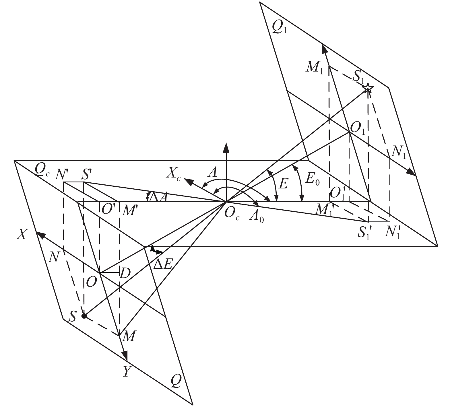
基于星图匹配脱靶量标定的指向模型如图1所示[13],该模型为单颗测量恒星的脱靶量标定图像光心的示意图,其余恒星的标定原理以此类推。
图1展示了观测恒星脱靶量至量度坐标的投影关系,S1为定标恒星的天球位置,S为恒星在探测器中的实测成像位置,OO1为望远镜的视轴,Q为CCD所在量度坐标系平面,Q1是过S1点且与Q面平行的平面,Oc为望远镜的主点,Qc是过Oc并与测站水平面平行的平面。M、N为S1在CCD中的成像分量位置,即两个脱靶量分量分别为ON和OM,O、S、M、N在平面Qc上的投影点分别记为O′、S′、M′、N′。[A0, E0]T表示望远镜视轴光心指向,[A, E]为定标恒星S1进行资料归算后的视位置方位角和高低角,[
ΔA, ΔE]T为恒星S1的脱靶量角值,OOc=f为望远镜的焦距, [x, y]T为观测恒星的量度坐标,根据图1中的几何关系: $$ \tan \Delta A = \frac{{M'S'}}{{{O_c}M'}} = \frac{{MS}}{{{O_c}M'}} = \frac{{x \cdot a}}{{O'{O_c} - O'M'}} $$ (1) $$ O'{O_c} = f\cos {E_0} $$ (2) $$ O'M' = OD = OM\sin {E_0} = y \cdot a \cdot \sin {E_0} $$ (3) 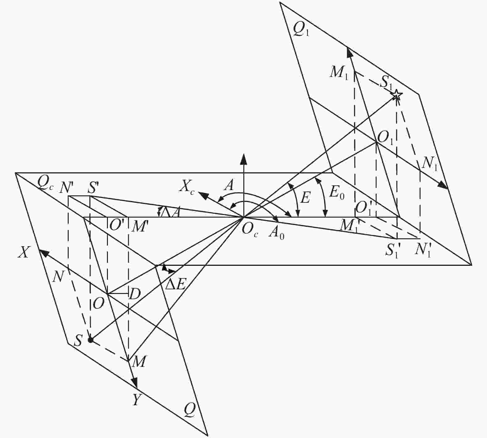
图 1 脱靶量标定指向模型
Figure 1. Star deviation calibration model
式中:f为望远镜的焦距;a为探测器的像元尺寸。综合公式(1)~(3):
$$ {A_0} = A - \arctan \left( {\frac{{x \cdot a}}{{f\cos {E_0} - y \cdot a \cdot \sin {E_0}}}} \right) $$ (4) 同理,通过推导可得:
$$ {E_0}=E-\frac{{y \cdot a}}{f} + \frac{{{{\left( {x \cdot a} \right)}^2}}}{{2{f^2}}}\tan {E_0} $$ (5) 求解公式(5)时注意到,E0∈[0, π/2],所以公式(5)具有唯一解。
将采集图像中所有匹配的测量恒星拟合评估出望远镜的实际指向:
$$ \left\{ \begin{gathered} {{\bar A}_0}{\text{ = }}\frac{{\displaystyle\sum\limits_{i = 0}^n {{A_{0i}}} }}{n} \\ {{\bar E}_0}{\text{ = }}\frac{{\displaystyle\sum\limits_{i = 0}^n {{E_{0i}}} }}{n} \\ \end{gathered} \right. $$ (6) 式中:[A0i, E0i]为第i颗定标恒星根据脱靶量模型标定出的望远镜光心指向。将标定的指向与望远镜编码器提供的指向相比较,得出指向修正量:
$$ \left\{ \begin{gathered} \Delta A = {{\bar A}_0}-{A_{encoder}} \\ \Delta E = {{\bar E}_0}-{E_{encoder}} \\ \end{gathered} \right. $$ (7) -
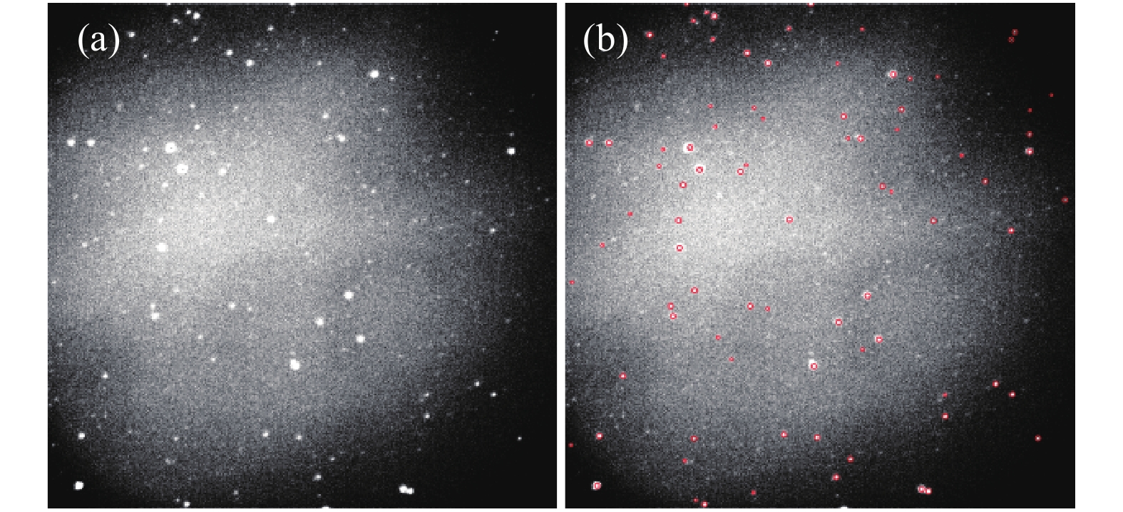
星图预处理包括观测恒星的质心坐标提取、星表筛选以及定标恒星位置资料归算。恒星质心的度量坐标调用Source-Extractor软件对采集图像进行阈值分割、轮廓提取和质心提取,如图2所示。质心坐标提取是将图像数据转化为度量坐标,如图3所示,为星图匹配提供基础。
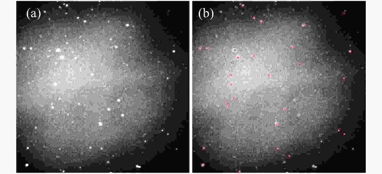
图 2 (a) 采集图像;(b) 测量恒星质心提取
Figure 2. (a) Grabbing image; (b) Extraction of measured star centroid
星表筛选与资料规算的目的同样是服务于星图匹配,选用Tycho-2恒星星表,根据测站望远镜的地理纬度ϕ、方位和俯仰电机编码器提供的粗略指向[Aencoder, Eencoder]以及视场D筛选出星表在当前指向的定标恒星经纬 (α, δ)位置的筛选范围:
$$ \left\{ \begin{array}{l} \alpha = LST - \arcsin \left(\dfrac{{\sin {E_{encoder}} \cdot \sin {A_{encoder}}}}{{\cos \delta }}\right) \pm \dfrac{D}{2} \\ \delta = {{\rm{arc}}} ({\rm{sin}} \phi \cdot \sin {E_{encoder}} - \cos \phi \cdot \sin {E_{encoder}} \cdot \\ \qquad \cos {A_{encoder}}) \pm \dfrac{D}{2} \end{array} \right. $$ (8) 式中:LST为地方恒星时。过滤掉暗星以及自行比较大的恒星(大于10 mas/a),挑选出星等介于 8 ~ 10的均匀分布的定标星群,筛选后的星表包括赤经(α)和赤纬(δ)、自行等基本参数。
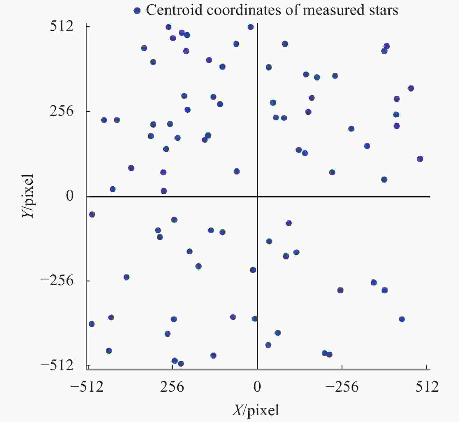
图 3 测量恒星质心坐标提取
Figure 3. Extraction of measured star centroid coordinates
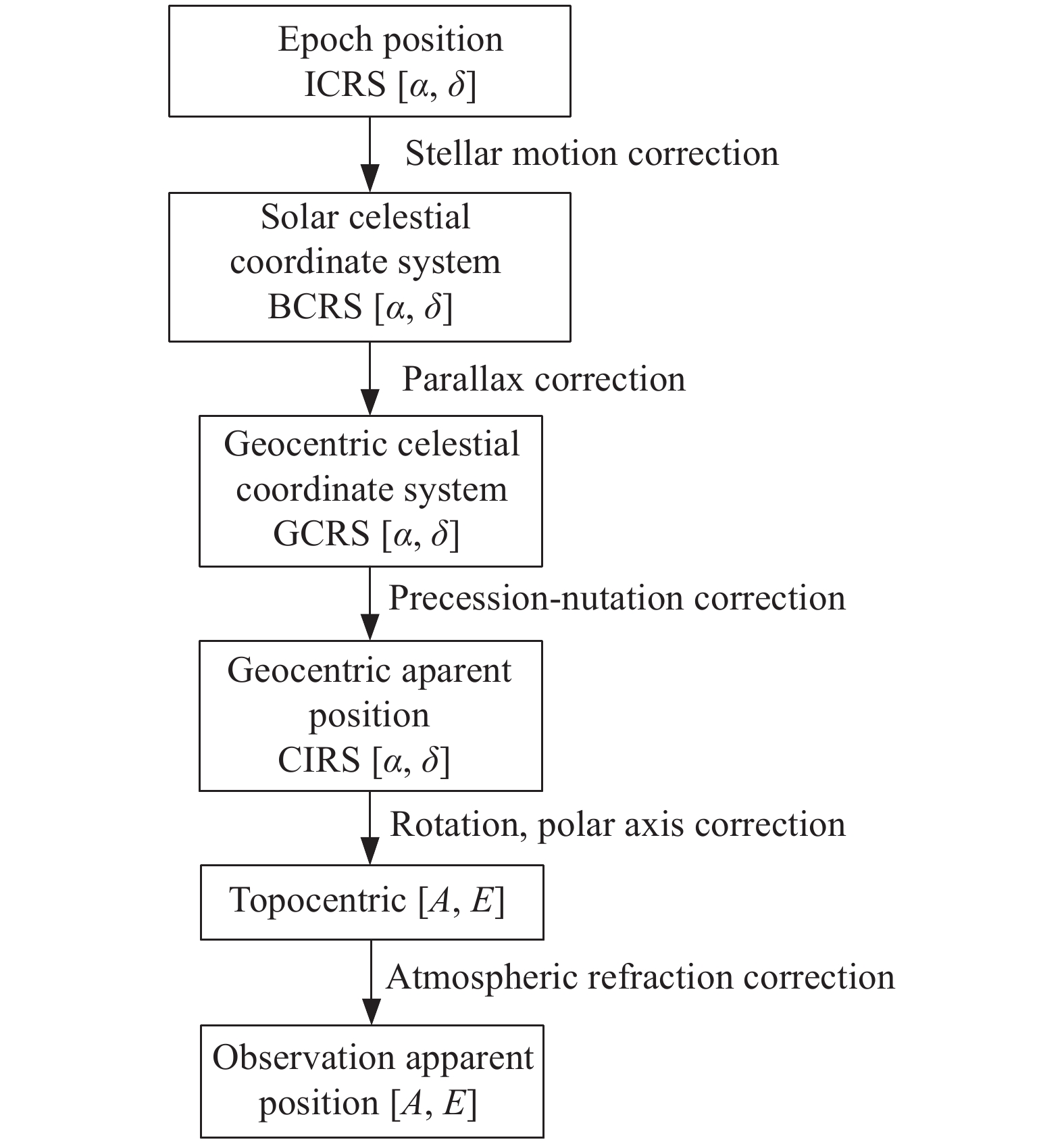
需要注意的是,从Tycho-2恒星星表筛选出的恒星群为在J2000.0历元天球坐标系(ICRS)下的平位置,而星图匹配的最终目的是获得定标恒星的视位置,从ICRS到视位置的过程即资料归算,资料归算的流程图如图4所示。

图 4 定标恒星资料规算流程图
Figure 4. Flow chart of calibration star data conversation
调用SOFA程序包进行定标恒星位置的资料归算,将筛选后的标定恒星群在J2000历元下的平位置 (ICRS)归算至地心视位置(CIRS),然后根据观测时间、测站所在经纬度以及环境参数等等基本信息将CIRS下的经纬度归算至测站视位置,即标定恒星的方位角和俯仰角[A, E]。
-
星图匹配算法应用于建立测量恒星与定标恒星的对应关系。该算法基于高鲁棒性的三角形匹配算法[14],但传统算法特征维数少且构建三角形过多,造成计算大量的冗余匹配,且视场边缘定标恒星的位置的畸变较大,不利于最终评估光心指向。文中采用的匹配算法增加了脱靶量特征维度,首帧匹配只需构建一组距离光心最近的测量恒星构成特征三角形,利用恒星两两之间的角距进行匹配识别。首帧匹配后计算底片常数,序列图像的匹配根据底片常数计算出多颗测量恒星的天球坐标并与星表中的定标恒星位置做比较,是否在限差内完成匹配。这种算法的优势在于增加了脱靶量特征维数,构建三角形速度快,且三角形距离视轴距离近使得位置信息准确,并最终通过调整限差大小,剔除边缘视场的恒星降低畸变影响,有效地保证了最终望远镜光心指向的评估精度。
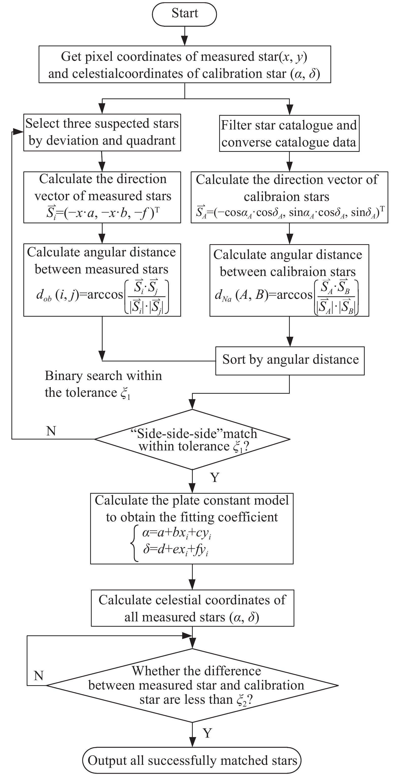
面向脱靶量标定的星图匹配算法基于三角形匹配算法中的“边-边-边”[15],即利用恒星两两之间的角距进行匹配识别,如图5所示。
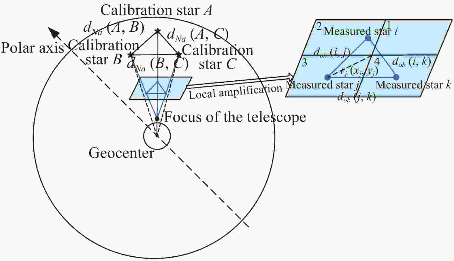
图 5 面向脱靶量标定的星图匹配算法示意图
Figure 5. Schematic diagram of star pattern matching algorithm for deviation calibration
筛选出介于8~10星等的测量恒星群,将采集图像分成四个象限,每个象限中的测量恒星按照脱靶量
$ {r_i}({x_i},{y_i}) = \sqrt {{x_i}^2 + {y_i}^2} $ 进行排序,逆时针选取每个象限中脱靶量最小的恒星构建三角形(Si, Sj, Sk)进行匹配,分象限可以剔除双星以及共线的恒星。计算测量恒星间的角距:$$ {d_{ob}}\left( {i,j} \right) = \arccos \left( {\frac{{{{\overset{\lower0.5em\hbox{$\smash{\scriptscriptstyle\rightharpoonup}$}} {S} }_i} \cdot {{\overset{\lower0.5em\hbox{$\smash{\scriptscriptstyle\rightharpoonup}$}} {S} }_j}}}{{\left| {{{\overset{\lower0.5em\hbox{$\smash{\scriptscriptstyle\rightharpoonup}$}} {S} }_i}} \right| \cdot \left| {{{\overset{\lower0.5em\hbox{$\smash{\scriptscriptstyle\rightharpoonup}$}} {S} }_j}} \right|}}} \right) $$ (9) 式中:
${\overset{\lower0.5 em\hbox{$\smash{\scriptscriptstyle\rightharpoonup}$}} {S} _i}={\left( {-x \cdot a,-x \cdot b,-f} \right)^{\rm{T}}}$ ;a为CCD的像元尺寸;f为望远镜焦距。计算定标恒星之间的角距,并按角距大小顺序排列:
$$ {d_{Na}}\left( {A,B} \right) = \arccos \left( {\frac{{{{\overset{\lower0.5em\hbox{$\smash{\scriptscriptstyle\rightharpoonup}$}} {S} }_A} \cdot {{\overset{\lower0.5em\hbox{$\smash{\scriptscriptstyle\rightharpoonup}$}} {S} }_B}}}{{\left| {{{\overset{\lower0.5em\hbox{$\smash{\scriptscriptstyle\rightharpoonup}$}} {S} }_A}} \right| \cdot \left| {{{\overset{\lower0.5em\hbox{$\smash{\scriptscriptstyle\rightharpoonup}$}} {S} }_B}} \right|}}} \right) $$ (10) 式中:
${\overset{\lower0.5 em\hbox{$\smash{\scriptscriptstyle\rightharpoonup}$}} {S} _A}={\left( {-{\text{ cos}}{\alpha _A} \cdot \cos {\delta _A},{\text{sin}}{\alpha _A} \cdot \cos {\delta _A},\sin {\delta _A}} \right)^{\rm{T} }}$ ;$ \left( {{\alpha _A},{\delta _A}} \right) $ 为定标恒星的赤道坐标。采用二分法查表法遍历测量恒星角距在定标恒星的角距历表中是否满足:$$ \left\{ \begin{gathered} \left| {{d_{Na}}\left( {A,B} \right)-{d_{ob}}\left( {i,j} \right)} \right| \leqslant {\xi _1} \\ \left| {{d_{Na}}\left( {A,C} \right)-{d_{ob}}\left( {i,k} \right)} \right| \leqslant {\xi _1} \\ \left| {{d_{Na}}\left( {B,C} \right)-{d_{ob}}\left( {j,k} \right)} \right| \leqslant {\xi_1} \\ \end{gathered} \right. $$ (11) 式中:
$\xi _1 $ 为角距测量不确定度。若公式(11)成立,则测量恒星与定标恒星匹配成功。否则返回起始步骤,逐步放大脱靶量并逆时针寻找新的恒星重新构建三角形直至匹配成功。利用这匹配成功的恒星计算底片常数模型:$$ \left\{ \begin{gathered} \alpha = a + b{x_i} + c{y_i} \\ \delta = d + e{x_i} + f{y_i} \\ \end{gathered} \right. $$ (12) 利用底片常数可由其他测量恒星的量度坐标(x, y)计算出其天球坐标(α, δ)并与星表位置进行比较,如果匹配无误,则测量恒星的天球坐标位置与定标恒星位置应小于匹配阈值门限ξ2,即:
$$ \sqrt {{{\left( {{\alpha _{measured}}-{\alpha _{calibration}}} \right)}^2}{{\cos }^2}\delta + {{\left( {{\delta _{measured}}-{\delta _{calibration}}} \right)}^2}} \leqslant {\xi _2} $$ (13) 依据望远镜畸变程度,ξ2取0.1″~10″,位置差大于ξ2即认为可剔除匹配星,反之则匹配成功。面向脱靶量标定的星图匹配算法流程如图6所示。
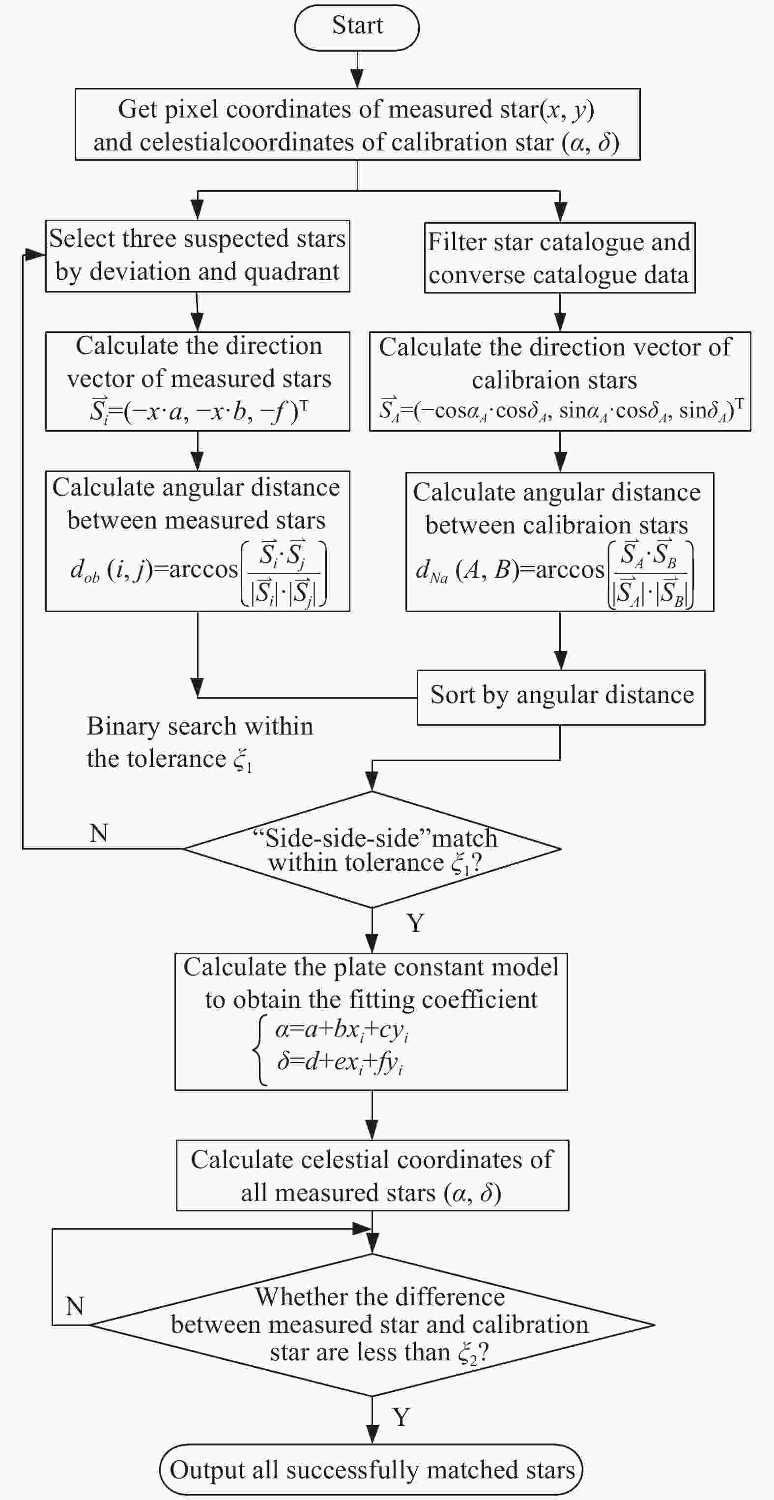
图 6 面向脱靶量标定的星图匹配算法流程图
Figure 6. Flow chart of star pattern matching algorithm for deviation calibration
-
为了验证上述指向修正方法的有效性以及修正精度,实验依托位于经度125.4443°,纬度43.7907°的测站400 mm口径的光电望远镜进行指向修正算法的验证,望远镜的相关参数如表1所示,测试程序使用 C++/OpenCV 编写,测试平台处理器为 i7-2600@3.4 GHz,内存 8.00 GB。
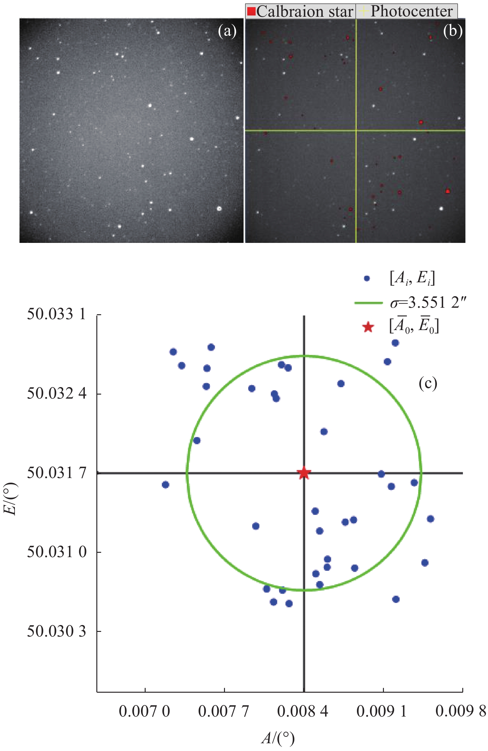
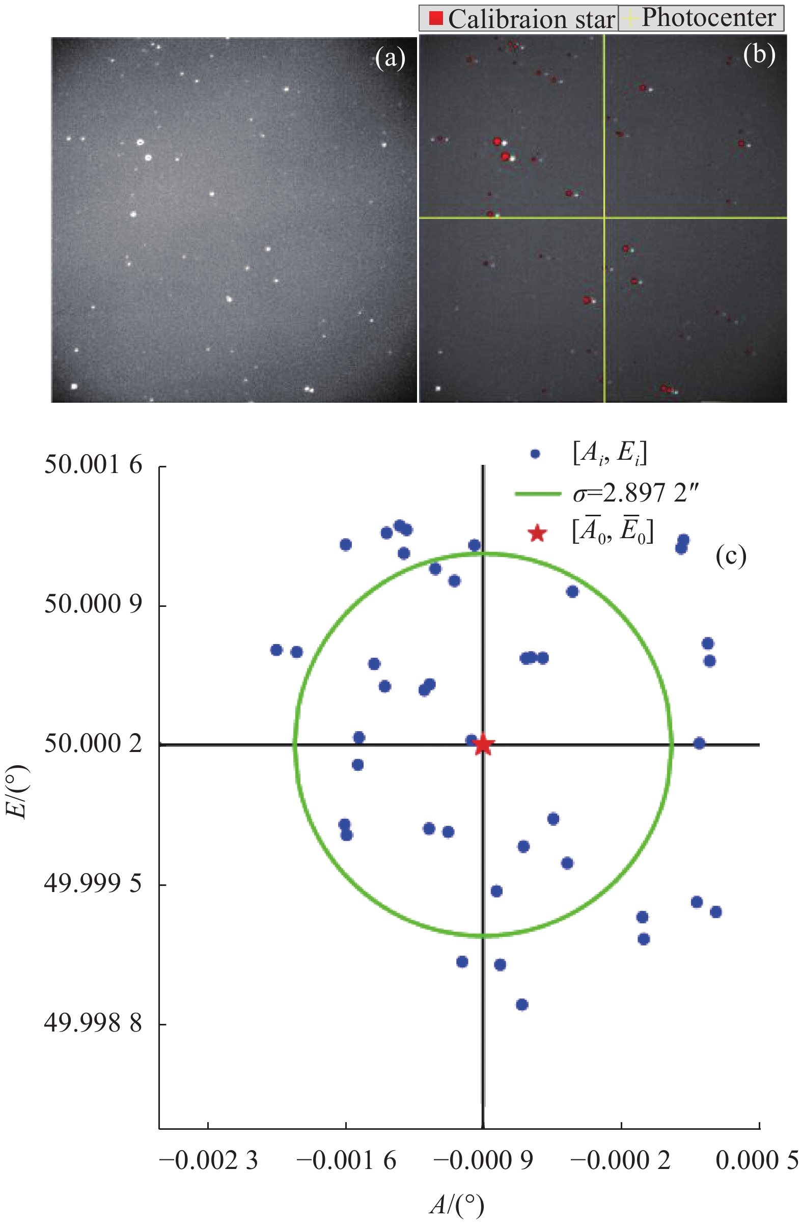
望远镜采集一组序列图像对指向进行修正,采集过程中采用短曝光模式,修正周期为 2.2 s,其中曝光采集图像耗时0.11 s,首帧图像的星图预处理与星图匹配处理时间为0.8 s,序列图像的星图预处理与星图匹配时间为0.626 s,指向修正耗时1.467 s。针对指向为[0.0002°, 50.0001°]的天区进行修正,完成30帧序列图像的指向修正,匹配阈值门限ξ2取值1″,首帧指向拟合结果如图7所示,经过序列图像的修正,从第10帧后修正量基本趋于稳定,末帧修正结果如图8所示。
表 1 望远镜的相关参数
Table 1. Related parameters of the telescope
System parameter Value Focal length/mm 600 Field of view/(″) 57×57 Resolution of CCD 1 024×1 024 Pixel size/μm 11×11 Distortion 1% 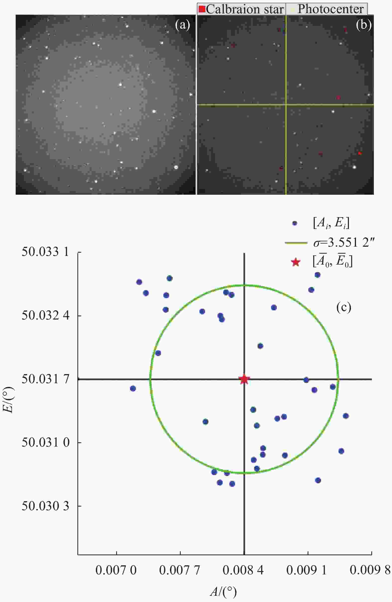
图 7 (a) 首帧采集图像;(b)首帧星图匹配;(c)首帧光心指向拟合
Figure 7. (a) Captured image by first frame; (b) Star pattern matching by first frame; (c) Pointing fitting of photocenter direction by first frame
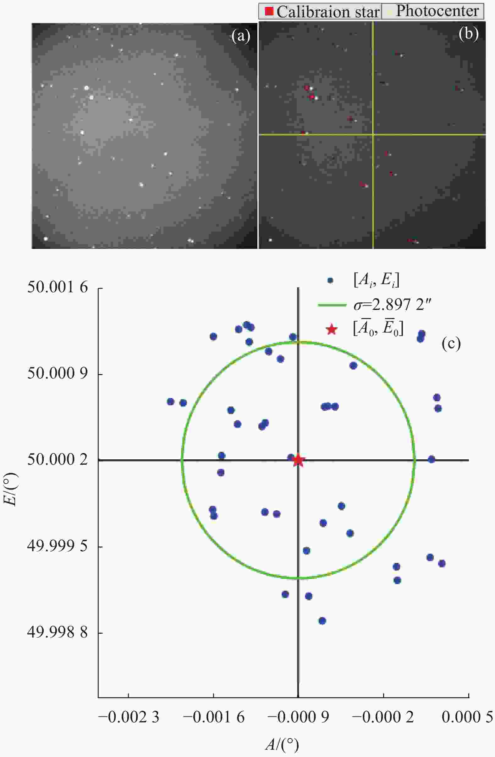
图 8 (a) 末帧采集图像;(b) 末帧星图匹配;(c) 末帧光心指向拟合
Figure 8. (a) Captured image by last frame; (b) Star pattern matching by last frame; (c) Pointing fitting of photocenter direction by last frame
由图7、图8观察可知,首帧望远镜指向为[0.0084°, 50.0317°],由多颗测量恒星位置反算出的光心指向残差的均方根误差为3.5512″,修正后的末帧指向为[−0.0009°, 50.0002°],光心指向残差的均方根误差为2.8972″,即望远镜的指向由修正前的 1.96′提高到了4.21″。
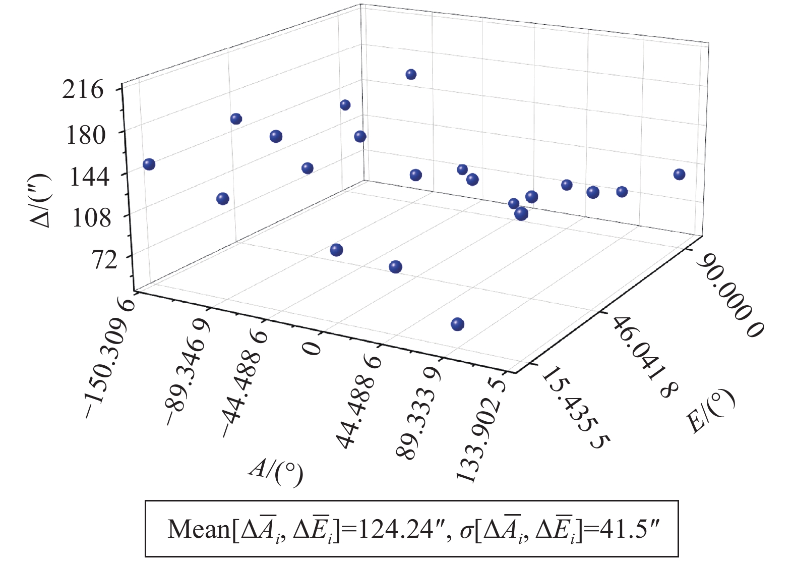
采用上述实验方法对全天区典型分布的一批子天区进行指向误差修正,修正前的指向误差分布如图9所示,修正后的误差分布如图10所示。从实验数据分析可知,全天区的指向误差均值由修正前的 124.24″提高到了4.97″,标准差从41.50″提高到了4.76″。
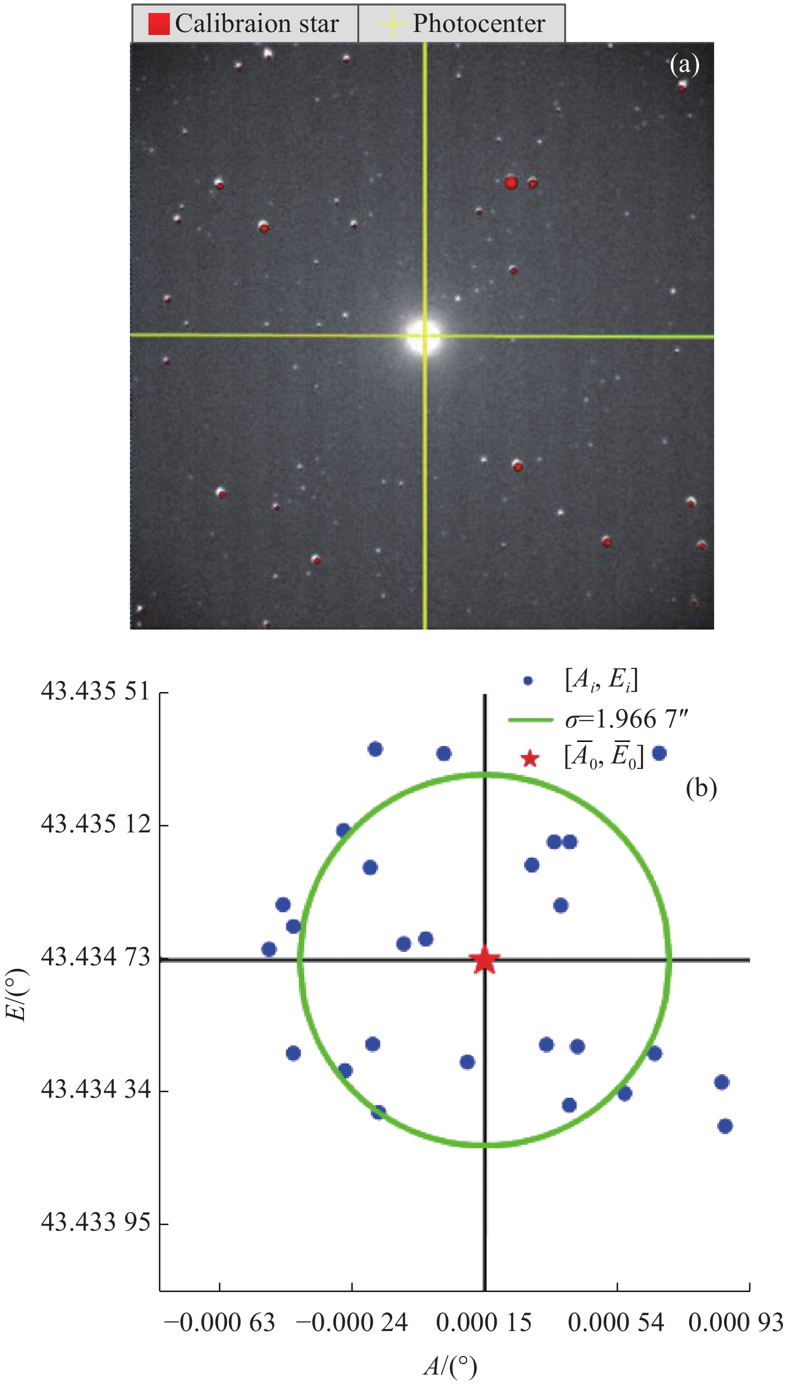
为了验证该方法对于指向标准源北极星的指向精度,望远镜指向北极星,经资料规算后北极星的理论指向为[0°, 43.4352°]。经过序列图像的修正后,从第8帧后修正量基本趋于稳定,修正后的指向为[0.00015°, 43.43473°],如图11所示。
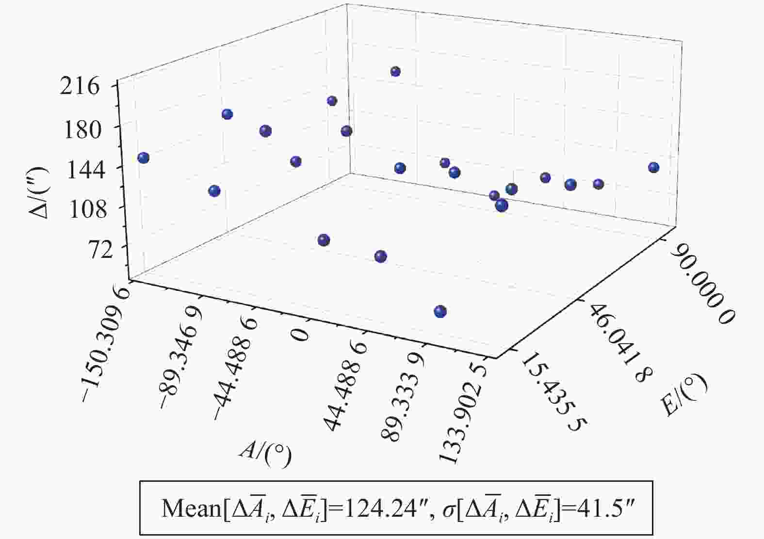
图 9 修正前指向误差分布
Figure 9. Distribution of pointing residue without corrected

图 10 修正后指向误差分布
Figure 10. Distribution of pointing residue after corrected
由图11分析可知,修正后的光心指向相较于理论值的差距为1.776",望远镜指向北极星时的指向精度较高。

图 11 (a) 指向北极星的星图匹配;(b) 指向北极星的光心指向拟合
Figure 11. (a) Star pattern matching by pointing at Polaris; (b) Pointing fitting of photocenter direction by pointing at Polaris
-
通过上述实验验证,针对畸变为1%的望远镜进行指向修正,测量恒星的天球坐标位置与定标恒星位置的匹配阈值门限取值1″时,全天区典型分布的一批子天区的指向误差均值由修正前的124.24″提高至4.97″,标准差从41.50″提高至4.76″,且星图匹配稳定可靠。可见文中提出的基于星图匹配脱靶量标定的指向误差修正方法的精度与镜头畸变密切相关,畸变较大时可以通过放大阈值门限完成匹配,但修正精度与误匹配概率都会受到影响,所以良好的望远镜光学质量是保障高精度的指向修正的前提条件。
文中提供了一种基于星图匹配脱靶量标定的指向误差修正方法,首帧匹配基于三角形特征匹配算法提高匹配的鲁棒性,并增加了脱靶量特征维数加快构建特征三角形,序列图像通过比较测量恒星的天球坐标与定标恒星距离是否在阈值门限内完成匹配,将多颗匹配的恒星坐标位置带入脱靶量标定修正模型完成光心指向的拟合与标定。针对复杂的移动测站的工况条件,该方法的可靠性和修正精度较高,适合应用于移动测站的指向修正场合。同时,该方法的修正过程与望远镜机架结构无关,因此也可适用于赤道式或地平式等不同机架结构的望远镜。
Pointing correction technology of telescope of mobile tracking station based on star pattern matching deviation calibration
-
摘要: 目前,移动测站以其高机动性正逐步成为空间目标监测网络重要的系统组成,应用于空间目标的共视观测与精密跟踪。针对移动测站光电望远镜由于工况的不稳定性以及装调过程中存在的指向误差,文中提出了一种基于星图匹配脱靶量标定的指向误差修正方法。首先,根据编码器轴系定位筛选出定标星群并进行资料归算;其次,采用面向脱靶量标定的快速星图匹配算法识别出与测量恒星相匹配的定标星坐标,并作为理论位置;最后,将多颗测量恒星坐标带入脱靶量标定指向修正数学模型对望远镜的指向进行拟合与标定。实验结果证明:采集一组序列图像对光心指向进行修正,单帧图像的修正周期约为2.2 s,从第10帧后修正量基本趋于稳定。对全天区典型分布的一批子天区进行指向修正,指向误差均值由修正前的124.24″提高至4.97″,标准差从41.50″提高至4.76″。综上所述,基于星图匹配脱靶量标定的指向误差修正方法对于提高测站望远镜的指向精度效果显著,且该方法的修正过程与望远镜机架结构无关,因此也可适用于不同机架结构的望远镜指向修正。Abstract:
Significance At present, the mobile tracking station, with its advantages of high mobility, high flexibility, wide observation range and low networking cost, is gradually becoming an important system component in the space target monitoring network and is widely used for common-view observation and precision tracking of spatial objectives. The rapid angular velocity motion of the space debris causes the dynamic axis of the telescope to become unstable during tracking, resulting in a dynamic bias in the telescope's pointing. In particular, the operating conditions of the mobile station are complex and frequently changing, leading to deviations in the pointing accuracy provided by the telescope's encoder. However, precise pointing accuracy is a prerequisite for astronomical positioning and target identification by optoelectronic telescopes, so dynamic pointing errors in mobile stations must be corrected to ensure the accuracy of space target positioning. To address the dynamic pointing errors caused by the above factors, a pointing error correction method based on star pattern matching deviation calibration is provided. Methods Firstly, the acquired images are processed by extracting the centroid coordinates of the measured stars, filtering the catalogue of calibration stars, and converting the stellar position coordinates. The Source-Extractor software is used to perform threshold segmentation, contour extraction and centroid coordinate extraction of the measured stars on the acquired images (Fig.2). The catalogue of calibration stars is filtered by the rough pointing provided by the telescope's encoder to determine the population of calibrated stars at the current pointing and the field of view. The SOFA package is called to perform a coordinate transformation of the coordinates of the calibration stars, transforming the flat position of the filtered calibration star at J2000 to the apparent position of the station, i.e. the azimuth and elevation of the calibration stars (Fig.4); Secondly, a rapid star pattern matching algorithm for star deviation calibration is used to identify the coordinates of calibration stars that match the measured stars, and take them as the theoretical positions. The star pattern matching algorithm for the first frame is based on classical triangle matching to improve robustness and adds star deviation calibration features to speed up the construction of feature triangles (Fig.5), the matching of subsequent frames uses the plate constants derived from the first frame to calculate the celestial coordinates of the measured star and compares them with the calibration stars in the filtered catalogue to determine whether the difference is within the tolerance limits (Fig.6); Finally, the pixel coordinates of all the measured stars are brought into a mathematical model of star deviation calibration to fit and calibrate the telescope pointing (Fig.1). Results and Discussions In order to verify the effectiveness of the pointing correction method and the accuracy of the correction, a verification experiment of the pointing correction algorithm was carried out on a 400 mm aperture photoelectric telescope at a station located at 125.4443° longitude and 43.7907° latitude. The relevant telescope parameters are given (Tab.1). The experimental results demonstrate that the correction period of a single frame is about 2.2 s when a set of sequential images is acquired to correct the optical centre pointing, and the amount of correction generally stabilises from the 10th frame onwards. The pointing corrections were applied to a group of sub-sky regions with a typical distribution of the total sky area, and the mean pointing error is increased from 124.24″ to 4.97″ (Fig.9) and the standard deviation is increased from 41.50″ to 4.76″ before the correction (Fig.10). The telescope was pointed at the standard source Polaris, and the corrected photocentre pointing is 1.776″, which is different from the theoretical value, that is, the correction accuracy of this method is better than 1.8″ (Fig.11). Conclusions The above experiments show that the pointing correction method based on star pattern matching deviation calibration is effective in improving the pointing accuracy of the station's telescope. The method is reliable and accurate in complex mobile station conditions and is suitable for correcting the pointing of the mobile station's telescope. In addition, the correction process is independent of the telescope's frame configuration, so it can be applied in pointing corrections for telescopes with different frame configurations, such as equatorial or geostrophic. -
Key words:
- optoelectronic telescope /
- pointing error /
- star pattern matching /
- space target
-
图 2 (a) 采集图像;(b) 测量恒星质心提取
Figure 2. (a) Grabbing image; (b) Extraction of measured star centroid
图 5 面向脱靶量标定的星图匹配算法示意图
Figure 5. Schematic diagram of star pattern matching algorithm for deviation calibration
图 6 面向脱靶量标定的星图匹配算法流程图
Figure 6. Flow chart of star pattern matching algorithm for deviation calibration
图 7 (a) 首帧采集图像;(b)首帧星图匹配;(c)首帧光心指向拟合
Figure 7. (a) Captured image by first frame; (b) Star pattern matching by first frame; (c) Pointing fitting of photocenter direction by first frame
图 8 (a) 末帧采集图像;(b) 末帧星图匹配;(c) 末帧光心指向拟合
Figure 8. (a) Captured image by last frame; (b) Star pattern matching by last frame; (c) Pointing fitting of photocenter direction by last frame
图 11 (a) 指向北极星的星图匹配;(b) 指向北极星的光心指向拟合
Figure 11. (a) Star pattern matching by pointing at Polaris; (b) Pointing fitting of photocenter direction by pointing at Polaris
表 1 望远镜的相关参数
Table 1. Related parameters of the telescope
System parameter Value Focal length/mm 600 Field of view/(″) 57×57 Resolution of CCD 1 024×1 024 Pixel size/μm 11×11 Distortion 1%  下载: 导出CSV
-
[1] Huang Fuyu, Shen Xueju, He Yongqiang, et al. Performance analysis of super-wide field of view imaging system used for space target detection [J]. Infrared and Laser Engineering, 2015, 44(10): 3134-3140. (in Chinese) [2] Fu Qiang, Shi Haodong, Wang Chao, et al. Research on new technology of photoelectric detection for space-based space debris [J]. Space Debris Research, 2020, 20(4): 49-55. (in Chinese) [3] Li Z. Research on optoelectronic observation technologies for space objects [D]. Beijing: University of Chinese Academy of Sciences, 2014. (in Chinese) [4] 刘影. 一种便于移动的天文望远镜: 中国, CN201710472987.0[P]. 2017-06-21. [5] Chen Long, Liu Chengzhi, Li Zhenwei, et al. Non-cooperative common-view observation of LEO space objects and initial orbit determination [J]. Acta Optica Sinica, 2021, 41(19): 1912003. (in Chinese) doi: 10.3788/AOS202141.1912003 [6] 张晓祥. 实时测定天文望远镜指向误差的方法: 中国, CN201110361031.6[P]. 2011-11-15. [7] Wang Jianjun, Lu Changming, Huang Chen, et al. System error correction model for equatorial telescopes [J]. Journal of Spacecraft TT& C Technology, 2013, 32(1): 57-60. (in Chinese) [8] Huang L. Research on pointing error and shafting technologies for large telescope [D]. Beijing: University of Chinese Academy of Sciences, 2016. (in Chinese) [9] Yan L. Research on line-of-sight pointing prediction technology for electro-optical telescope [D]. Beijing: University of Chinese Academy of Sciences, 2014. (in Chinese) [10] 李锦英. 一种提高望远镜小区域指向精度的方法: 中国, CN107272181 A[P]. 2017-10-20. [11] Liang Xiaobo, Ma Wenli, Zhou Jin, et al. Star identification algorithm based on image normalization and Zernike moments [J]. IEEE Access, 2020, 8(4): 29228-292237. [12] Liang Xiaobo, Zhou Jin, Ma Wenli, et al. Method of distortion and pointing correction of a ground-based telescope [J]. Applied Optics, 2019, 58(19): 5136-5142. (in Chinese) doi: 10.1364/AO.58.005136 [13] 刘丙申, 胡绍林, 柴敏, 等. 光学跟踪测量数据处理[M]. 北京: 国防工业出版社, 2014. [14] Zhang G J. Star Identification[M]. Beijing: National Defense Industry Press, 2011. (in Chinese) [15] Wang Jun, He Xin, Wei Zhonghui, et al. Fast star identification algorithm based on multi-feature matching [J]. Optics and Precision Engineering, 2019, 27(8): 1870-1879. (in Chinese) -

 点击查看大图
计量
- 文章访问数: 73
- HTML全文浏览量: 18
- PDF下载量: 21
- 被引次数: 0


