


-
近年来,随着全球气候的不断恶化和资源的持续枯竭,人们对海洋勘探系统的研究越来越感兴趣。而水下无线通信(Underwater Wireless Communication, UWC)技术是实现海洋探测的关键技术。UWC技术是以射频(Radio Frequency, RF)、声波和光波为无线载波,来达到信息交换的目的。考虑到RF和声学方法对距离和带宽的限制[1],水下光学无线通信(Underwater Optical Wireless Communication, UOWC)系统已成为一种有吸引力且可行的替代方案。
由于海水对可见光具有吸收、散射和湍流特性,海水对可见光的强衰减作用是高鲁棒性水下通信的重大障碍[2]。水下无线光通信采取的光源仅限450~550 nm窗口范围内的蓝绿光[3],且大功率激光光源的调制速率一般较低,无法实现高速且长距离的信息传输。为了提高速率,研究人员通常会选择正交幅度调制(Quadrature Amplitude Modulation, QAM)等高阶调制方式[4],但QAM调制技术需要线性较好的光源和信道,限制了光源发射光功率,导致使用高阶调制技术的水下无线光通信系统的水下传输距离较近[5-6],在良好水质下传输距离不超过20 m,因此实现高速且长距离UOWC的关键技术之一在于使用可高速调制技术的大功率的激光输出。在自由空间光学(Free Space Optical, FSO)通信[7]中,为了获得大功率的信号光,通常会使用光放大器直接对信号光进行放大[8],或采用大功率的激光器与间接调制的相结合技术输出大功率的信号光。由于缺少蓝绿光波段的光放大器,直接对蓝绿光信号放大实现大功率水下激光输出的方案在UOWC系统中难以实现。
目前,大功率激光产生可使用基频光放大后通过非线性晶体的二次谐波(Second Harmonic Generation, SHG)理论实现,该技术目前主要集中用于制造脉冲或连续激光器。2019年,清华大学使用连续光通过MgO:PPLN晶体实现了7 W的绿光输出[9]。2019年,南安普顿大学使用脉冲光通过MgO:PPLN波导,采用SHG技术以70%的转换效率得到1 W的780 nm光[10]。2020年,南安普顿大学使用连续光通过PPLN波导,采用SHG技术实现了74%转换效率下2.5 W的780 nm光输出[11],但该类激光器均需通过调制晶体才能实现高速大功率蓝绿光信号输出,但是目前尚无基于蓝绿光波段的调制晶体,因此无法实现对大功率蓝绿光激光器进行调制。
随后,研究者尝试将调制后的1064 nm基频光进行放大,然后通过非线性晶体的准相位匹配技术,将已调制的基频光转换为大功率532 nm的信号光,由此实现大功率的高速调制的蓝绿信号光输出,从而可实现长距离的水下无线光通信。
2008年,加州大学的Frank等人[12]首次提出了借助于非线性晶体的二次谐波变换产生绿光从而实现长距离的水下无线光通信的方法,该系统首次实现了2 m水箱范围内2 Gbps速率的通信。但该系统的工作温度高达180 ℃,不利于系统进行长时间的水下工作,且该系统在通信测试方面没有针对载波信号进行通信性能测试。2021年,西安邮电大学的杨祎等人[13]设计了一套常温下的基于波长转换技术的UOWC通信系统,实现了100 m长距离下100 Mbps的通信。但该系统同样没有针对载波信号的通信性能测试。
当前,非线性晶体发生SHG效应实现波长转换所使用的技术普遍对非线性晶体的外部环境要求较高,特别是实现高效波长转换需要较高的匹配温度[14],而应用于水下温度较低,高温工作条件需要消耗较大的功率,同时波长转换技术对信号特征的影响规律未见分析,特别是高速大功率的倍频激光输出对信号特性的影响未见报道。因此,该研究设计了一套可以应用于常温下的高速绿光大功率发射系统,并分析常温下的大功率输出对高速信号特征的影响规律,从而推动高速大功率无线光通信在水下高速长距离无线通信中的应用。
-
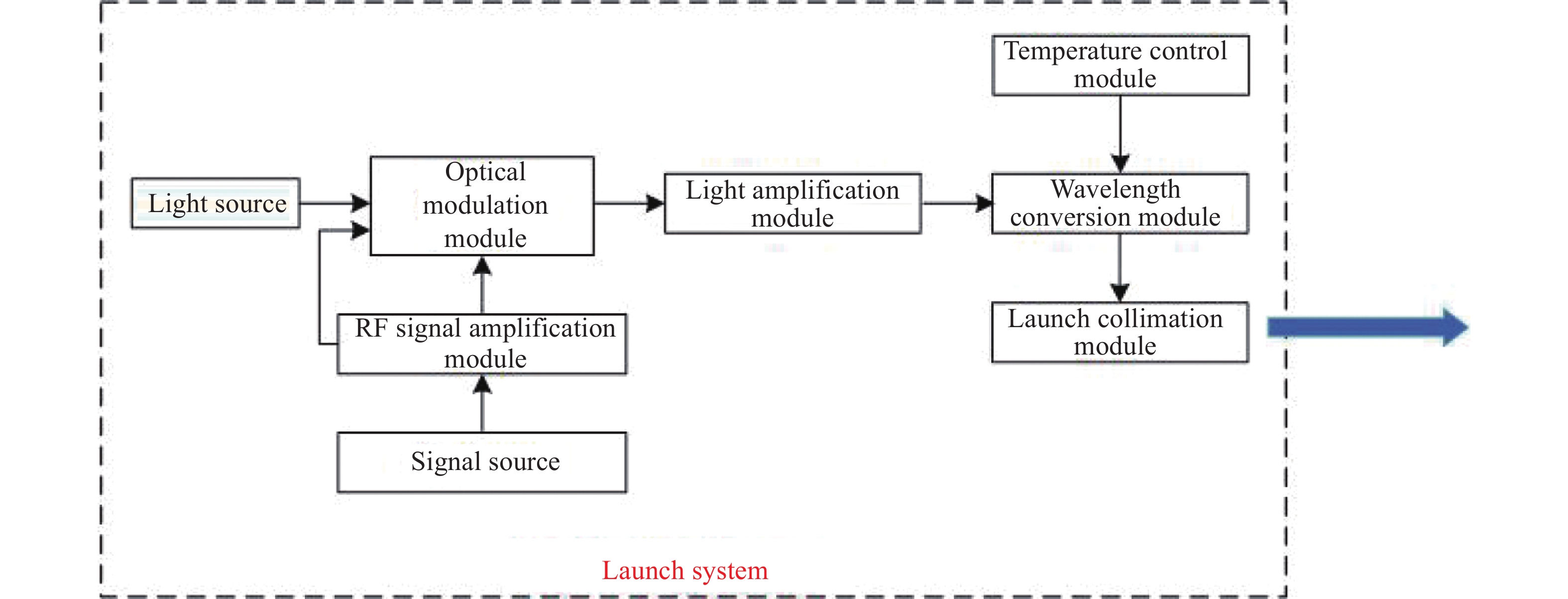
该系统的设计框图如图1所示,由八个模块组成,分别为光源模块、光调制模块、射频信号放大模块、信号源、光放大模块、波长变换模块、温控模块和光纤准直模块。

图 1 系统设计框图
Figure 1. System design block diagram
光源模块使用窄线宽保偏1064 nm的分布式反馈激光器(Distributed Feedback laser, DFB)实现小功率连续激光输出。
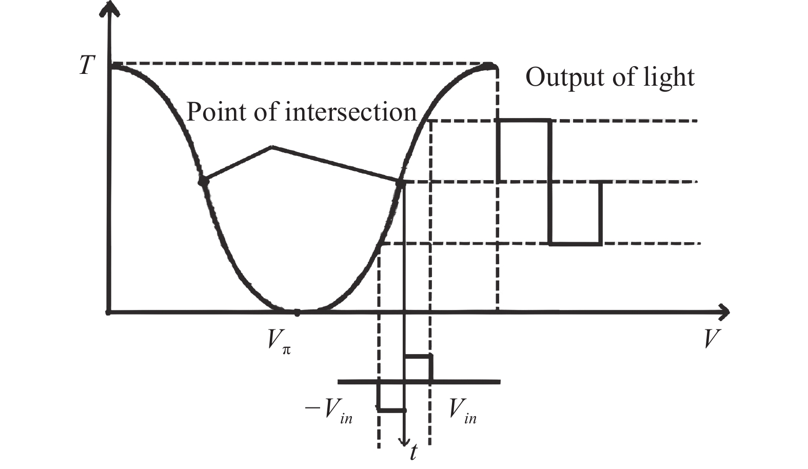
光调制模块使用铌酸锂晶体(LiNbO3)作为外调制器实现数字和模拟信号的电光强度调制,工作原理如图2所示,调制系数T如公式(1)所示:

图 2 强度调制器光路工作原理图
Figure 2. Schematic diagram of the optical path of the intensity modulator
$$ T = \frac{1}{2} + \frac{1}{2}\cos\left( {\Delta \varphi } \right) = \frac{1}{2} + \frac{1}{2}\cos\left( {\pi \frac{{{V_{in}}}}{{{V_\pi }}}} \right) $$ (1) 式中:${V_{{{in}}}}$为加在电极上的电压幅度值;$\Delta \varphi = {\varphi _1} - \varphi {}_2$为两个支路所引起的相位之差,通常将这种通过合理选择两臂调制电压使得${\varphi _1} = - {\varphi _2}$的工作模式称为“推挽”工作模式;${V_\pi }/2$为直流偏置电压,它的选择直接影响信号的线性区域。
信号源使用了任意波形发生器和矢量信号源作为电信号的产生装置。由于驱动铌酸锂晶体工作需要较大的输入功率和直流偏置,因此使用射频信号放大模块对输入信号进行功率放大并提供${V_\pi }/2$的直流偏压。射频放大模块的带宽决定了系统的电信号带宽。
光放大模块使用掺镱光纤放大器对1064 nm红外光信号进行放光大。该系统的光放大模块分别为针对高速数字信号的窄脉冲光放大器和针对QAM-OFDM调制信号的模拟放大器。窄脉冲光放大器是通过预放大、一级放大和二级放大实现大于20 W的红外信号光输出。信号的输出光功率可表示为:
$$ \begin{split} {P_{out}} = &{P_s}\left( L \right) \times \left( {1 - {R_2}\left( {{\lambda _s}} \right)} \right) = \left( {\frac{{{P_{sat}}\sqrt {{R_1}} }}{{\sqrt {{R_1}} \left( {1 - {R_2}} \right) + \sqrt {{R_2}} \left( {1 - {R_2}} \right)}}} \right. \\& \left\{ {\frac{{{g_0}\left( 0 \right) + N{\varGamma _s}{\sigma _\alpha }\left( {{\lambda _s}} \right)}}{{{\sigma _{\alpha_ p}}{\varGamma _p}N + {\alpha _p}}}} \right. \cdot \left( {1 - \exp\left[ { - L\left( {{\sigma _{\alpha_ p}}{\varGamma _p}N + {\alpha _p}} \right)} \right]} \right) -\\& N{\varGamma _s}{\sigma _\alpha }\left( {{\lambda _s}} \right)L\left. {\left. { - \ln\left( {\frac{1}{{\sqrt {{R_1}} {R_2}}}} \right)} \right\}} \right) \times \left( {1 - {R_2}\left( {{\lambda _s}} \right)} \right)\\[-18pt] \end{split} $$ (2) 式中:${P_{{{sat}}}} = \hbar {V_{{s}}}A/{\varGamma _{{s}}}{\sigma _e}({\lambda _s})\tau$,${V_s}$为激光频率;${\alpha _p}$为$\lambda = {\lambda _p}$时的散射损耗;${g_0}(0)$为小信号增益;${\lambda _p}$和${\lambda _s}$为抽运光和激光的波长;${\varGamma _p}$为抽运光耦合进纤芯百分比,它可由纤芯面积与内包层面积比得到;${\varGamma _s}$为激光在纤芯中的百分比,可由光纤的模式理论得出;${\sigma _{\alpha p}}$为抽运光的吸收截面;${R_1} = 0.98$;${R_2} = 0.04$。
波长转换模块使用PPLN晶体通过设计光学结构实现波长转换,在通过控制温度以及晶体额尺寸和位置达到准相位匹配后实现大功率的倍频光输出,最后通过光纤准直结构设计,将倍频信号光通过光纤耦合和准直输出发射角可调的无线激光信号。
该系统的波长转换模块设计影响整个系统的输出功率和高速信号特性,所以波长转换模块是此系统的核心技术。
-
波长转换系统通过聚焦透镜、非线性晶体和耦合透镜组成的光学系统实现大功率的倍频光输出,波长转换系统的设计图如图3所示。

图 3 波长转换模块结构图
Figure 3. Structure diagram of wavelength conversion module
在波长转换设计中所有光学器件都是共轴的。在波长转换模块中首先通过准直透镜输出光放大模块传输来的大功率红外信号光。为了提高波长转换效率,增大辐照度,使用聚焦透镜将准直光束聚焦进入非线性晶体。其中,通过测试发现准直透镜与聚焦透镜间的距离在160 mm左右获得最佳的准直效果,聚焦透镜的焦距为120 mm,通过调整聚焦透镜和非线性晶体间的距离可以获得更高的辐照度,从而提高波长转换效率。
非线性晶体是波长转换系统的关键部分,由于MgO:PPLN晶体容易制备[15],且实际应用大量采用MgO:PPLN晶体作为非线性介质进行波长转换。因此本系统也使用MgO:PPLN晶体作为波长转换的媒介,晶体的规格是25 mm×2 mm×1 mm。
非线性晶体由图3中的温控模块控制晶体温度,并通过晶体下方的三相调节器控制光束的入射角度,实现系统对波长转换温度和角度的控制。
红外光经过非线性晶体发生波长转换,输出光为蓝绿光。再通过光阑进入滤光片滤除红外光后,通过耦合透镜将大功率的蓝绿信号光输入光纤中,送往光纤准直模块。经过测试,非线性晶体和耦合透镜间的距离为100 mm且耦合透镜和光纤支架间的距离为30 mm时可以得到最佳的耦合效率。
-
该系统所使用的波长转换技术是三阶非线性效应下的二次谐波产生过程。该过程常用以下耦合波方程组表示为:
$$ \begin{split}& \frac{{\partial {E_1}\left( z \right)}}{{\partial z}} =\frac{{i{\omega _1}}}{{c{n_1}}}{d_{eff}}{E_2}\left( z \right) \cdot E_1^*\left( z \right){{\rm{e}}^{ - i\Delta kz}}\\& \frac{{\partial {E_2}\left( z \right)}}{{\partial z}} = \frac{{i{\omega _1}}}{{c{n_2}}}{d_{eff}}E_1^2\left( z \right){{\rm{e}}^{ - i\Delta kz}} \\ \end{split}$$ (3) 式中:${E_1}$表示基频光的场强;${E_2}$表示倍频光的场强;${\omega _1}$,${\omega _2}$表示基频光和倍频光的频率,且有${\omega _2} = 2{\omega _1}$;${d_{eff}}$为有效非线性系数;$\Delta k$为波矢失配量。得到倍频后的耦合方程可表示为:
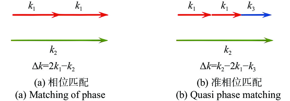
$$ E_{2}(L)=\frac{\omega_{1}}{c n_{1} \Delta k} d_{eff} E_{1}^{2}(0)\left[\sin \left(\frac{\Delta k L}{2}\right) \Bigg/\left(\frac{\Delta k L}{2}\right)\right] $$ (4) 式中:$\Delta k $为相位匹配时的波矢适配参数。由于相位匹配对系统的稳定性要求很高,在实际操作中很难达到,因此该系统使用了准相位匹配(e+e→e)来实现,准相位匹配技术在实际的匹配过程中通常要求系统输入的基频光为e光,同时通过非线性晶体产生的倍频光也为e光,因此准相位匹配可以简写为e+e→e。准相位匹配和相位匹配的波矢匹配情况如图4所示。
图4中,${k_1} = (2\pi {\omega _1}{n_1})/c$代表基频光的波矢,${k_2} = (2\pi {\omega _2}{n_2})/c$代表倍频光的波矢,${k_3} = 2\pi /\Lambda $为准相位匹配中的补偿量,通过设计晶体中的光栅周期来实现。因此在准相位匹配下,波矢失配量可表示为:
$$ \Delta k = 2 \times \frac{{2\pi {\omega _1}n_e^{2\omega }\left( {T,\theta ,\lambda } \right)}}{c} - \frac{{2\pi {\omega _2}n_e^\omega \left( {T,\theta ,\lambda } \right)}}{c} - \frac{{2\pi }}{\varLambda } $$ (5) 
图 4 波矢关系
Figure 4. Wave vector relationship
其中,$\varLambda $为晶体的光栅周期,定义式为:
$$ \varLambda = \frac{{2\pi }}{{{{n}}_e^{2\omega }\left( {T,\theta ,\lambda } \right) - 2n_e^\omega \left( {T,\theta ,\lambda } \right)}} $$ (6) 式中:$n_e^{2\omega }(T,\theta ,\lambda )$和$n_e^\omega (T,\theta ,\lambda )$分别指倍频光的折射率和基频光的折射率;$(T,\theta ,\lambda )$代表该折射率受到温度、角度和入射光波长的影响。根据晶体中折射率和角度的关系,以及准相位匹配e+e→e实现的实现条件,$n_e^{2\omega }(T,\theta ,\lambda )$和$n_e^\omega (T,\theta ,\lambda ) $的定义为:
$$ \frac{1}{{\left[{n}_{e}^{\omega \text{,}2\omega }\left({\theta }_{m}\right)\right]}^{2}}=\frac{\cos^{2}{\theta }_{m}}{{n}_{o}^{2}}+\frac{\sin^{2}{\theta }_{m}}{{n}_{e}^{2}} $$ (7) 根据O.GAYER[16]的理论,$n_e^2$和$n_o^2$取决于晶体的性质和材料本身,有温度和折射率的关系如下:
$$ \begin{split}& n_o^2 = {a_1} + {b_1}f + \frac{{{a_2} + {b_2}f}}{{{\lambda ^2} - {{\left( {{a_3} + {b_3}f} \right)}^2}}} + \frac{{{a_4} + {b_4}f}}{{{\lambda ^2} - a_5^2}} - {a_6}{\lambda ^2} \\& n_e^2 = {a_1} + {b_1}f + \frac{{{a_2} + {b_2}f}}{{{\lambda ^2} - {{\left( {{a_3} + {b_3}f} \right)}^2}}} + \frac{{{a_4} + {b_4}f}}{{{\lambda ^2} - a_5^2}} - {a_6}{\lambda ^2} \end{split}$$ (8) $$ \begin{split} f =& \left( {T - {T_0}} \right)\left( {T + {T_0} + 2 \times 273.16} \right) =\\& \left( {T - 24.5} \right)\left( {T + 570.82} \right) \end{split} $$ (9) 式中:$T$为MgO:PPLN晶体的温度,K;$\lambda $为入射光波长,mm。
所以准相位匹配时的波矢适配$\Delta k$可表示为:
$$ \begin{split} \Delta k = &2 \times \frac{{2\pi {\omega _1}n_e^{2\omega }\left( {T,\theta ,\lambda } \right)}}{c} - \frac{{2\pi {\omega _2}n_e^\omega \left( {T,\theta ,\lambda } \right)}}{c} - \\& \left( {{{n}}_e^{2\omega }\left( {T,\theta ,\lambda } \right) - 2n_e^\omega \left( {T,\theta ,\lambda } \right)} \right) \end{split} $$ (10) 结合公式(4)推导出该系统的转换效率模型为:
$$ \eta = \frac{{{P_{out}}}}{{{P_{in}}}} = \frac{{16d_{eff}^2{\pi ^2}LP}}{{c{\varepsilon _0}n_e^{2\omega }\left( {T,\theta ,\lambda } \right)n_e^\omega \left( {T,\theta ,\lambda } \right){\lambda ^3}}} \cdot \sin{c^2}\left( {\frac{{\Delta kL}}{2}} \right) $$ (11) 式中:L为晶体长度;P为平均发射光功率。由公式(11)可以看出,在波长转换过程中为了达到最大的倍频转换效率,使$\Delta k = 0$,从而令$\sin{c^2}(\Delta kL/2) = 1$达到最佳转换效率。
-
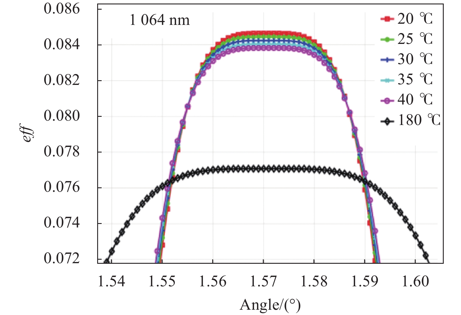
由于该系统主要应用于水下无线光通信中,受限于450~550 nm的水下通信波长,以及光放大器技术,因此系统光源需要选择基频波长在1064 nm附近。为使设计的系统工作在较高转换效率,从理论上先仿真分析系统参数即波长、角度和温度对波长转换系统转换效率的影响。系统水下工作时,工作温度为室温,不同温度与匹配角的关系如图5所示。设基频光输出功率为1.4 W,根据公式(10)得到转换效率与温度和角度的关系如图6所示。由此可以看出,无论波长光和温度怎样变化,角度在1.57°附近都能达到最佳匹配$\Delta k = 0$,转换效率达到最大。但是观察图6在同一波长下随着温度的升高,波矢失配量$\Delta k = 0$对应的角度可调范围增大,但是转换效率却在降低。
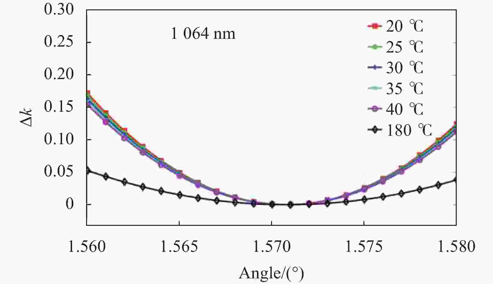
图 5 不同温度下最佳效率对应的角度关系
Figure 5. Angle relationship corresponding to the best efficiency at different temperatures

图 6 1064 nm下不同温度对应的转换效率
Figure 6. Conversion efficiency at 1064 nm at different temperatures
-
光束质量是激光光束特性的核心参数之一,决定通信速率。高斯型激光光束用${M^2}$因子定义光束能量,针对该系统波长转换前后的通信质量变化情况,激光束的光束质量${M^2}$可以通过下式求出:
$$ \begin{split}& {\omega ^2}\left( {z'} \right) = a{\left( {z' - c} \right)^2} + b \\& {M^2} = \sqrt {ba} {\pi \mathord{\left/ {\vphantom {\pi \lambda }} \right. } \lambda } \end{split}$$ (12) 式中:$ z' $指实际测量的坐标值;$c$为实际测量中的零点与光束束腰位置的偏离值;设以光束束腰位置为零点的坐标为$z$,则$ z' = z + c $;$a$和$b$代表拟合计算出的参数。通过公式(12)计算出$a$和$b$的值,然后再求出光束质量。
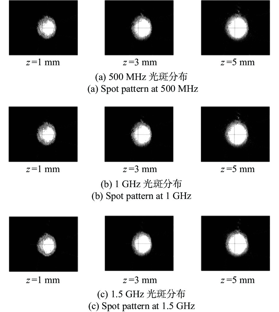
种子光源在直流光源时的光束质量${M^2} \approx 1.02$。该系统测试了波长转换前后的光束质量变化情况,分别采集1 mm、3 mm和5 mm位置处光斑的半径,使用载波频率在500 MHz、1 GHz和1.5 GHz下,调制方式为4QAM-OFDM的信号基频光输出的光斑图像,如图7所示。

图 7 波长转换前光斑图
Figure 7. Spot diagram before wavelength conversion
测试数据如表1所示,通过公式(12)得到了波长转换前的光束质量。
表 1 不同信号频率下波长转换前的测试结果
Table 1. Test results before wavelength conversion at different signal frequencies
Signal frequency 1 mm spot
size/mm3 mm spot
size/mm5 mm spot
size/mmM2 500 MHz 1.795 1.945 2.105 2.76 1 GHz 1.595 1.745 1.915 2.34 1.5 GHz 1.815 2.000 2.275 3.35 分析表1中不同速率下波长转换前的测试结果,光束质量的均值为2.837,方差为0.516。对比DFB种子光源输出的激光光束质量,经过光调制和光放大后的光束质量显著下降。然后,分别测量了波长转换后500 MHz、1 GHz和1.5 GHz频率下4 QAM-OFDM信号的532 nm光斑结果,如图8所示。

图 8 波长转换后光斑图
Figure 8. Spot diagram after wavelength conversion
波长转换后532 nm对应的测试结果及光束质量计算结果如表2所示。在表2测试结果的基础上,对表中光束质量因子的测试结果进行处理得到均值为2,方差为0.0104。由此可以看出,波长转换后的532 nm激光光束质量相比波长转换前的1064 nm激光光束质量显著变好。
表 2 不同信号频率下波长转换后的测试结果
Table 2. Test results after wavelength conversion at different signal frequencies
Signal frequency 1 mm spot
size/mm3 mm spot
size/mm5 mm spot
size/mmM2 500 MHz 0.990 1.070 1.230 1.94 1 GHz 0.980 1.110 1.230 1.98 1.5 GHz 0.950 1.090 1.270 2.08 通过对系统光束质量的测量可以看出,波长转换系统后信号光的光束质量明显变好,这是因为波长转换后的光强分布近似为门函数的特性,因此该系统适合用于水下高速无线光通信。
-
该系统实现的是大功率绿光的高速通信,因此在保证波长转换系统的转换效率和光束模式质量的同时,还需要保证高速信号的波形完整性。系统在基频信号光平均功率10 W时,常温下测试转换效率到达20%[13],保证532 nm绿光输出1 W以上,波长转换系统实验装置如图9所示,该系统尺寸为400 mm×150 mm×200 mm。
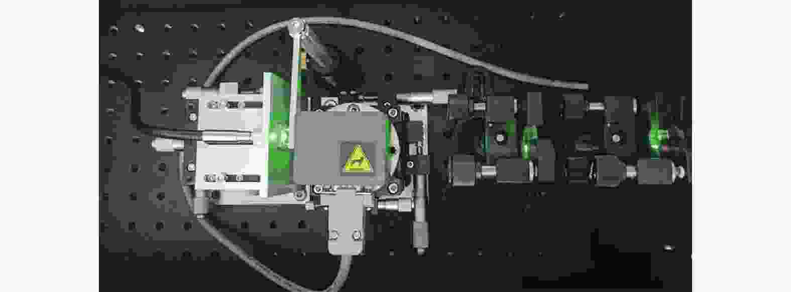
图 9 波长转换系统实验图
Figure 9. Experimental setup of wavelength conversion system
系统测试了脉冲宽度分别为5 ns、2 ns和1 ns的信号在波长转换系统温度20 ℃,532 nm绿光输出功率为1 W时,探测器带宽2 GHz采集得到的信号波形如图10所示。将脉冲信号幅度的10%~90%所占的时间宽度作为信号的上升沿宽度,脉冲信号幅度的90%~10%所占用的时间宽度作为信号的下降沿宽度。上升沿宽度和下降沿宽度在波长转换前后的变换情况表明了脉冲信号的形变情况。

图 10 方波信号上升沿下降沿示意图
Figure 10. Schematic diagram of the rising edge and falling edge of a square wave signal
将基频信号的上升沿(下降沿)的数据${{{t}}_\omega }$对倍频信号的上升沿(下降沿)数据做差值${{{t}}_{2\omega }}$得到的相对变化量结果$\Delta t = {t_\omega } - {t_{2\omega }}$再除以对基频信号的上升沿(下降沿)数据得到信号上升沿(下降沿)数据的相对变化量$t' = \Delta t/{t_{2\omega }}$,拟合结果如图11所示。
从图11(a)可以看出,窄脉冲信号上升沿的相对变化量值随着脉冲宽度减小是一个趋于稳定的过程,并收敛在0.27附近;从图11 (b)可以看出,窄脉冲信号在经过波长转换模块后,下降沿发生压缩,随着脉冲信号脉宽的减小,压缩现象很快发生收敛。

图 11 窄脉冲信号相对变化量的拟合结果
Figure 11. The fitting result of the relative change of the narrow pulse signal
综合上升沿和下降沿的压缩数据分析,可以得出当脉冲信号的脉冲宽度低于4 ns时,信号的压缩现象保持稳定,因此波长转换系统适用高速通信系统,且对于高速通信系统性能更好。
-
现今的高速调制方式应用非常广泛,类似正交幅度调制(Quadrature Amplitude Modulation, QAM)加OFDM,这类信号以载波模拟波形在信道中传输。为了进一步验证这类系统的通信性能,该系统使用了不同载波频率的模拟正弦信号进行测试。为了方便比对信号的形变情况,取一个完整周期的正弦波波形,一个周期所占用的时间宽度定义为$\phi $变量,如图12所示。根据图12中的测试数据,对基频信号的时域波形宽度形变量和信号频率的变化关系进行了拟合,如图13所示。基频信号时域波形的宽度${\varPhi _v}$和信号频率所对应的理论时域宽度${\varPhi _0}$的差值,得到了$\Delta \varPhi = {\varPhi _v} - {\varPhi _0}$。

图 12 正弦波形变示意图
Figure 12. Diagram of sinusoidal waveform change
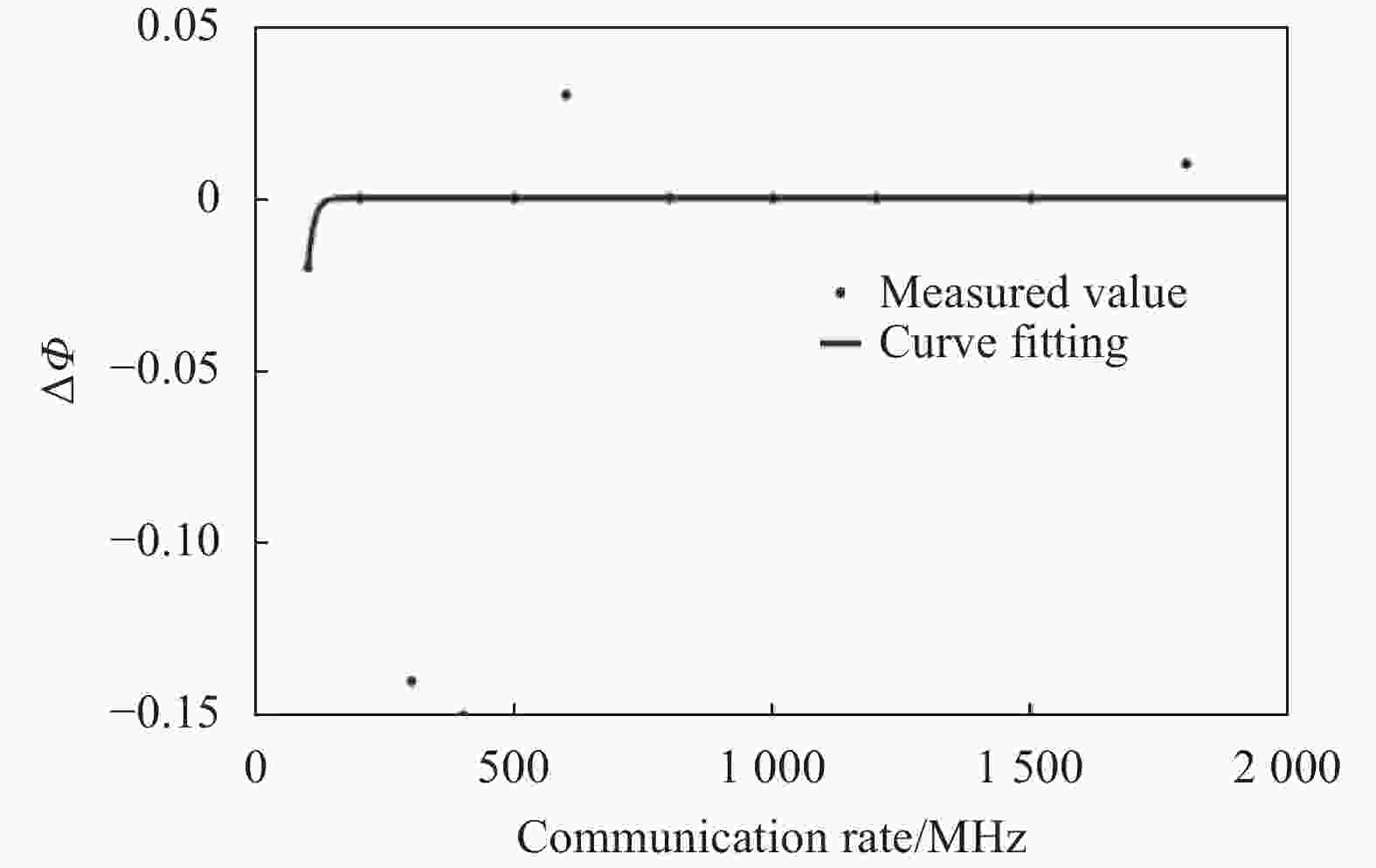
图 13 基频波形时域变化情况拟合曲线
Figure 13. Fitting curve of fundamental frequency waveform time-domain variation
通过图13可以看出,随着载波频率的提高,倍频信号的时域波形畸变降低,频率越高信号的时域波形更接近于理想波形。
为进一步分析波长转换前后高频信号波形畸变情况,在同一频率下对波长转换前信号对应的ϕ和波长转换后的信号对应的ϕ进行对比,得到了表3。通过对表3的数据进行分析,可以得出波长转换前后对高频正弦信号几乎没有影响。
表 3 基频信号和倍频信号的信号周期对比
Table 3. Signal period comparison of fundamental frequency signal and frequency multiplier signal
Signal frequency Fundamental frequency signal ϕ/ns Frequency multiplier signal ϕ/ns Variation/ns 500 MHz 2 2 0 1 GHz 1 1.03 +0.03 1.5 GHz 0.68 0.68 0 -
文中使用外调制和准相位匹配技术,将非线性光学二次谐波产生理论用于水下高速大功率无线激光发射系统,解决了高速无线光调制系统发射功率受限的问题。对设计的高速大功率无线激光调制发射系统进行了通信特性分析。实验结果表明:常温下,该系统输出的光斑光强分布均匀光束质量显著好于调制后的基频光模式。系统输出的方波信号上升沿宽度和下降沿宽度会发生压缩,但随着脉冲宽度的减小压缩现象会发生收敛,上升沿宽度收敛于0.27,下降沿宽度收敛于0.06,系统输出的正弦信号随着频率的增加没有发生明显的畸变。模拟和数字调制对系统的输出光束模式和高速信号波形畸变量均不影响。系统的532 nm无线激光平均输出功率小于1 W,可以实现长距离高速水下无线光通信。
Research on wavelength conversion system performance of high-power wireless optical communication
-
摘要: 针对水下高速无线激光通信发射功率较低,通信距离受限的问题,该研究采用非线性光学中二次谐波理论,将1064 nm的高速外调制与放大技术和非线性晶体的准相位匹配技术相结合,通过光学设计和系统参数研究,设计了一种532 nm的高速大功率无线激光调制发射系统,并建立了基于温度和角度变换的波长转换效率模型。然后通过仿真分析的方法得到了不同温度下,最大转换效率对应的角度范围。最后对系统的性能进行了系统搭建和实验分析,验证了该系统在常温下可实现1 W大功率532 nm绿光无线输出,且频率大于1 GHz的模拟信号和速率大于500 Mbps的数字信号调制。实验结果表明:常温下,该系统输出的光斑光强分布均匀,光束质量显著好于调制后的基频光模式。系统输出的方波信号上升沿宽度和下降沿宽度会发生压缩,但随着脉冲宽度的减小压缩现象会发生收敛,上升沿宽度收敛于0.27,下降沿宽度收敛于0.06,系统输出的正弦信号随着频率的增加没有发生明显的畸变。研究结果可以为未来水下长距离高速无线光通信应用提供理论和技术支撑。Abstract:
Objective With the increase of marine rights protection, marine resource development, and underwater exploration activities, wireless optical communication has become one of the key technologies for non-contact underwater information transmission due to its advantages of high speed, easy mobility, and good concealment. The absorption, scattering, and turbulence characteristics of visible light in seawater seriously restrict the underwater transmission distance of visible light communication systems. According to the transmission characteristics of visible light in seawater, blue-green light with the range of 450-550 nm is suitable for deep-sea wireless optical communication, which is less affected by seawater. In order to improve the capacity of wireless optical communication, high-order modulation methods such as Quadrature Amplitude Modulation (QAM) are often used in wireless optical communication systems. However, QAM modulation technology requires a linear light source and channel, which limits the emission power of the light source and reduces the underwater transmission distance for underwater wireless optical communication systems. In addition, it is difficult to quickly modulate a high-power laser light sources, so the high-power laser light cannot achieve high-speed optical carrier information transmission. Therefore, the wireless optical communication system with high-speed and high-power is one of the key technologies for long-distance underwater wireless optical communication. In order to obtain high-power signal light, Free Space Optical (FSO) communication usually uses optical amplifiers to directly amplify the signal light by combining the indirect modulation technology to output high-power signal light. However, it is difficult to directly amplify the blue-green light signal to achieve high-power underwater laser output in the UOWC system due to the lack of optical amplifiers in the blue-green light. Methods A high-power and high-speed underwater optical wireless communication (UOWC) system (Fig.1) with wavelength conversion construction (Fig.3) is designed, which adopts the second harmonic theory of nonlinear optics, as well as the 1 064 nm high-speed external modulation and the amplification technology. After analyzing the optical system and system parameters, the wavelength conversion efficiency model is deduced, and the relationship between the angle range and the conversion efficiency at different temperatures is obtained. Finally, the communication system is set up (Fig.9), and experimental analysis is carried out. Results and Discussions The effect of temperature on conversion efficiency and beam quality, as well as the performances of the square wave and sine wave are tested in this paper. The results show that the optimal matching can be achieved at an angle of around 1.57° (Fig.5), no matter how the wavelength and temperature change, the conversion efficiency can be maximized. At the same wavelength, the angle adjustable range corresponding to the wave vector mismatch would be increased with the increasing temperature, but the conversion efficiency will be decreased (Fig.6). Furthermore, the beam's uniform intensity distribution quality of doubling frequency mode is significantly better than that of the modulated fundamental frequency mode at room temperature (Fig.8). In addition, the width of the rising edge and the falling edge of the square wave signal would be compressed (Fig.10), whose relative variation of the rising edge tends to 0.27, and the relative variation of the falling edge tends to 0.06, but the compression phenomenon will converge with the increase of frequency (Fig.11). The sinusoidal signal has no noticeable distortion with the increase of frequency (Fig.12). Conclusions The designed system improves the beam quality compared to the modulated fundamental frequency light mode, and compresses the rising and falling edge widths of the square wave signal, which will converge with the pulse width decreases, but does not distort the sine signal with increasing frequency. So the system has no effect on the high-speed digital signal and high-frequency analog signal. It is verified that the designed system can achieve 1 W high-power 532 nm green light wireless output at room temperature, the analog signal frequency is higher than 1 GHz, and the digital signal rate is faster than 500 Mbps. The research results can provide theoretical and technical support for future long-distance high-speed underwater wireless optical communication. -
图 2 强度调制器光路工作原理图
Figure 2. Schematic diagram of the optical path of the intensity modulator
图 5 不同温度下最佳效率对应的角度关系
Figure 5. Angle relationship corresponding to the best efficiency at different temperatures
图 6 1064 nm下不同温度对应的转换效率
Figure 6. Conversion efficiency at 1064 nm at different temperatures
图 10 方波信号上升沿下降沿示意图
Figure 10. Schematic diagram of the rising edge and falling edge of a square wave signal
图 11 窄脉冲信号相对变化量的拟合结果
Figure 11. The fitting result of the relative change of the narrow pulse signal
图 13 基频波形时域变化情况拟合曲线
Figure 13. Fitting curve of fundamental frequency waveform time-domain variation
表 1 不同信号频率下波长转换前的测试结果
Table 1. Test results before wavelength conversion at different signal frequencies
Signal frequency 1 mm spot
size/mm3 mm spot
size/mm5 mm spot
size/mmM2 500 MHz 1.795 1.945 2.105 2.76 1 GHz 1.595 1.745 1.915 2.34 1.5 GHz 1.815 2.000 2.275 3.35  下载: 导出CSV
表 2 不同信号频率下波长转换后的测试结果
Table 2. Test results after wavelength conversion at different signal frequencies
Signal frequency 1 mm spot
size/mm3 mm spot
size/mm5 mm spot
size/mmM2 500 MHz 0.990 1.070 1.230 1.94 1 GHz 0.980 1.110 1.230 1.98 1.5 GHz 0.950 1.090 1.270 2.08
下载: 导出CSV
表 3 基频信号和倍频信号的信号周期对比
Table 3. Signal period comparison of fundamental frequency signal and frequency multiplier signal
Signal frequency Fundamental frequency signal ϕ/ns Frequency multiplier signal ϕ/ns Variation/ns 500 MHz 2 2 0 1 GHz 1 1.03 +0.03 1.5 GHz 0.68 0.68 0
下载: 导出CSV
-
[1] Pompili D, Akyildiz I F. Overview of networking protocols for underwater wireless communications [J]. IEEE Communications Magazine, 2009, 47(1): 97-102. doi: 10.1109/MCOM.2009.4752684 [2] 杨祎, 刘妍, 王艺龙, 张建磊, 杨方明. 水下复合信道对GMSK无线光通信系统性能的影响[J]. 红外与激光工程, 2022, 51(6): 20210622-1-11. Yang Yi, Liu Yan, Wang Yilong, et al. Influence of underwater composite channel on performance of GMSK wireless optical communication system [J]. Infrared and Laser Engineering, 2022, 51(6): 20210622. (in Chinese) [3] 陈祥子, 翁溶, 裴红梅. 不同温度、盐度海水中激光的衰减特性研究[J]. 海南热带海洋学院学报, 2019, 26(05): 93-100 Chen Xiangzi, Weng Rong, Pei Hongmei. Attenuation characteristics of laser in seawater with different temperature and salinity [J]. Journal of Hainan Tropical Ocean University, 2019, 26(5): 93-100. (in Chinese) [4] Koizumi Y, Toyoda K, Yoshida M, et al. 1024 QAM (60 Gbit/s) single-carrier coherent optical transmission over 150 km [J]. Optics Express, 2012, 20(11): 12508-12514. doi: 10.1364/OE.20.012508 [5] Al-halafi A, Shihada B. UHD video transmission over bidirectional underwater wireless optical communication [J]. IEEE Photonics Journal, 2018, 10(2): 1-14. [6] Chen Y, Kong M, Ali T, et al. 26 m/5.5 Gbps air-water optical wireless communication based on an OFDM-modulated 520-nm laser diode [J]. Optics Express, 2017, 25(13): 14760-14765. doi: 10.1364/OE.25.014760 [7] Xu J, Song Y, Yu X, et al. Underwater wireless transmission of high-speed QAM-OFDM signals using a compact red-light laser [J]. Optics Express, 2016, 24(8): 8097-8109. doi: 10.1364/OE.24.008097 [8] Khalighi M A, Uysal M. Survey on free space optical communication: A communication theory perspective [J]. IEEE Communications Surveys & Tutorials, 2014, 16(4): 2231-2258. [9] Lai J Y, Hsu C S, Hsu C W, et al. Single pass 7 watts continuous wave 532 nm generation by focusing optimized second harmonic generation in MgO: PPLN[C]//Nonlinear Frequency Generation and Conversion: Materials and Devices XVIII, 2019, 10902: 1090205. [10] Berry S A, Carpenter L G, Gray A C, et al. Zn-indiffused diced ridge waveguides in MgO: PPLN generating 1 watt 780 nm SHG at 70% efficiency [J]. OSA Continuum, 2019, 2(12): 3456-3464. doi: 10.1364/OSAC.2.003456 [11] Carpenter L G, Berry S A, Gray A C, et al. CW demonstration of SHG spectral narrowing in a PPLN waveguide generating 2.5 W at 780 nm [J]. Optics Express, 2020, 28(15): 21382-21390. doi: 10.1364/OE.395566 [12] Hanson F, Radic S. High bandwidth underwater optical communication [J]. Applied Optics, 2008, 47(2): 277-283. doi: 10.1364/AO.47.000277 [13] Yang Y, Fan L, He F, et al. Long-distance underwater optical wireless communication with PPLN wavelength conversion[C]//24th National Laser Conference & Fifteenth National Conference on Laser Technology and Optoelectronics, 2020, 11717: 117172J. [14] 桑梅, 薛挺, 于建, 等. PPLN 倍频效率与温度关系分析[J]. 光电子. 激光, 2002, 13(4): 343-348. Sang Mei, Xue Ting, Yu Jian, et al. Temperature dependence of the second harmonic generation in periodically poled LiNbO3 crystal [J]. Journal of Optoelectronics · Laser, 2002, 13(4): 343-348. (in Chinese) [15] Yamada M, Nada N, Saitoh M, et al. First order quasi phase matched LiNbO3 waveguide periodically poled by applying an external field for efficient blue second‐harmonic generation [J]. Applied Physics Letters, 1993, 62(5): 435-436. doi: 10.1063/1.108925 [16] Gayer O, Sacks Z, Galun E, et al. Temperature and wavelength dependent refractive index equations for MgO-doped congruent and stoichiometric LiNbO3 [J]. Applied Physics B, 2008, 91(2): 343-348. doi: 10.1007/s00340-008-2998-2 -

 点击查看大图
计量
- 文章访问数: 87
- HTML全文浏览量: 19
- PDF下载量: 32
- 被引次数: 0

